


DCS 600-1.7E
Sorensen DCS 600-1.7E, DCS 50-20E, DCS 300-3.5E, DCS 40-25E, DCS 150-7E User Manual
...
DCS-E SERIESDCS-E SERIES
April 28, 1998 Document No. M360761 Rev D
POWER SUPPLIESPOWER SUPPLIES
Instruction Manual
This manual covers models:
8-125E 60-18E
20-50E 80-13E
33-33E 150-7E
40-25E 300-3.5E
50-20E 600-1.7E
SORENSEN
Division of Elgar
9250 Brown Deer Road
San Diego, CA 92121-2294
1-800-525-2024
Tel: (858) 450-0085
Fax: (858) 458-0267
Email: sales@sorensen.com
www.sorensen.com
©1998 by Sorensen, Division of Elgar Electronics Corporation
This document contains information proprietary to Sorensen, Elgar Electronics Corporation. The information
contained herein is not to be duplicated or transferred in any manner without prior written permission from Sorensen.

SORENSEN FIVE–YEAR WARRANTY
Sorensen, a division of Elgar Electronics Corporation, warrants its products to be free from defects in
material and workmanship. This warranty is effective for five years from the date of shipment of the product
to the original purchaser. Liability of Sorensen under this warranty shall exist provided that:
• the Buyer exposes the product to normal use and service and provides normal maintenance on the
product;
• Sorensen is promptly notified of defects by the Buyer and that notification occurs within the warranty
period;
• the Buyer receives a Return Material Authorization (RMA) number from Sorensen’s Repair Department
prior to the return of the product to Sorensen for repair, phone 800-458-4258;
• the Buyer returns the defective product in the original, or equivalent, shipping container;
• if, upon examination of such product by Sorensen it is disclosed that, in fact, a defect in materials and/or
workmanship does exist, that the defect in the product was not caused by improper conditions, misuse,
or negligence; and,
• that Sorensen QA seal and nameplates have not been altered or removed and the equipment has not
been repaired or modified by anyone other than Sorensen authorized personnel.
This warranty is exclusive and in lieu of all other warranties, expressed or implied, including, but not limited
to, implied warranties of merchantability and fitness of the product to a particular purpose. Sorensen, its
agents, or representatives shall in no circumstance be liable for any direct, indirect, special, penal, or
consequential loss or damage of any nature resulting from the malfunction of the product. Remedies under
this warranty are expressly limited to repair or replacement of the product.
CONDITIONS OF WARRANTY
• To return a defective product, contact an Sorensen representative or the Sorensen factory for an RMA
number. Unauthorized returns will not be accepted and will be returned at the shipper’s expense.
• For Sorensen products found to be defective within thirty days of receipt by the original purchaser,
Sorensen will absorb all ground freight charges for the repair. Products found defective within the
warranty period, but beyond the initial thirty-day period, should be returned prepaid to Sorensen for
repair. Sorensen will repair the unit and return it by ground freight pre-paid.
• Normal warranty service is performed at Sorensen during the weekday hours of 7:30 am to 4:30 pm
Pacific time. Warranty repair work requested to be accomplished outside of normal working hours will
be subject to Sorensen non-warranty service rates.
• Warranty field service is available on an emergency basis. Travel expenses (travel time, per diem
expense, and related air fare) are the responsibility of the Buyer. A Buyer purchase order is required by
Sorensen prior to scheduling.
• A returned product found, upon inspection by Sorensen, to be in specification is subject to an inspection
fee and applicable freight charges.
• Equipment purchased in the United States carries only a United States warranty for which repair must
be accomplished at the Sorensen factory.
Committed to Quality...Striving for Excellence
i
SAFETY NOTICE
Before applying power to the system, verify that the DCS Series unit is configured properly for the user’s
particular application.
WARNING!
HAZARDOUS VOLTAGES IN EXCESS OF 280 VRMS, 600V PEAK MAY
BE PRESENT WHEN COVERS ARE REMOVED. QUALIFIED
PERSONNEL MUST USE EXTREME CAUTION WHEN SERVICING THIS
EQUIPMENT. CIRCUIT BOARDS, TEST POINTS, AND OUTPUT
VOLTAGES MAY BE FLOATING ABOVE (BELOW) CHASSIS GROUND.
Installation and service must be performed by qualified personnel who are aware of dealing with attendant
hazards. This includes such simple tasks as fuse verification.
Ensure that the AC power line ground is connected properly to the DCS Series unit input connector
or chassis. Similarly, other power ground lines including those to application and maintenance
equipment must be grounded properly for both personnel and equipment safety.
Always ensure that facility AC input power is de-energized prior to connecting or disconnecting the
input/output power cables.
During normal operation, the operator does not have access to hazardous voltages within the
chassis. However, depending on the user’s application configuration, HIGH VOLTAGES
HAZARDOUS TO HUMAN SAFETY may be generated normally on the output terminals.
Ensure that the output power lines are labeled properly as to the safety hazards and that any
inadvertent contact with hazardous voltages is eliminated. To guard against risk of electrical
shock during open cover checks, do not touch any portion of the electrical circuits. Even when the power if
off, capacitors can retain an electrical charge. Use safety glasses during open cover checks to avoid
personal injury by any sudden failure of a component.
Due to filtering, the unit has high leakage current to the chassis. Therefore, it is essential to operate this unit
with a safety ground.
Some circuits are live even with the front panel switch turned off. Service, fuse verification, and
connection of wiring to the chassis must be accomplished at least five minutes after power has
been removed via external means; all circuits and/or terminals to be touched must be safety
grounded to the chassis.
After the unit has been operating for some time, the metal near the rear of the unit may be hot enough to
cause injury. Let the unit cool before handling.
Qualified service personnel need to be aware that some heat sinks are not at ground, but at high potential.
These operating instructions form an integral part of the equipment and must be available to the operating
personnel at all times. All the safety instructions and advice notes are to be followed.
Neither Sorensen, San Diego, California, USA, nor any of the subsidiary sales organizations can accept any
responsibility for personal, material or consequential injury, loss or damage that results from improper use of
the equipment and accessories.
iii
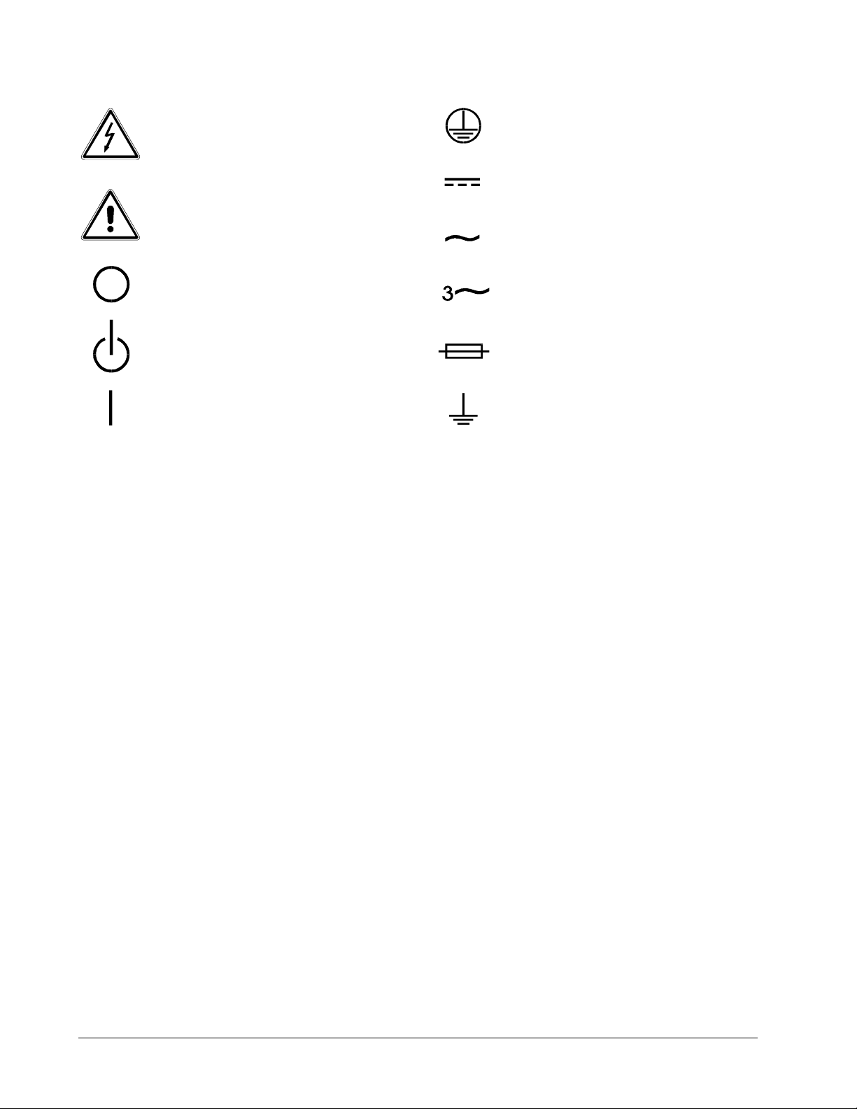
SAFETY SYMBOLS
Alternating Current
CAUTION
Risk of Electrical Shock
CAUTION
Refer to Accompanying Documents
Off (Supply)
Standby (Supply)
On (Supply)
ABOUT THIS MANUAL
Protective Conductor Terminal
Direct Current (DC)
Alternating
Three–Phase
Fuse
Earth (Ground) Terminal
Current (AC)
This manual has been written expressly for the Sorensen DCS 1KW series of power supplies
which have been designed and certified to meet the 1997 Low Voltage and Electromagnetic
Compatibility Directive Requirements of the European Community. Units that comply with the
directive are designated by an ‘E’ after the model designator (e.g., DCS 40-25E would indicate
that the model is certified) when configured for 230 VAC input only.
Since the goal of the Low Voltage Directive is to ensure the safety of the equipment operator,
universal graphic symbols (see below) have been used both on the unit itself and in this manual
to warn the operator of potentially hazardous situations.
iv

TABLE OF CONTENTS
SECTION 1. FEATURES AND SPECIFICATIONS.............................................................................................1-1
1.1 DESCRIPTION ........................................................................................................................................................1-1
1.2 OPERATING MODES...............................................................................................................................................1-1
1.3 POWER SUPPLY FEATURES.....................................................................................................................................1-1
1.4 SPECIFICATIONS....................................................................................................................................................1-2
1.4.1 Electrical Specifications................................................................................................................................1-2
1.4.2 Mechanical Specifications.............................................................................................................................1-3
SECTION 2. INSTALLATION AND OPERATING INSTRUCTIONS...............................................................2-1
2.1 GENERAL..............................................................................................................................................................2-1
2.2 INITIAL INSPECTION ..............................................................................................................................................2-1
2.3 INSTALLATION ......................................................................................................................................................2-1
2.3.1 Input Voltage Selection ................................................................................................................................2-1
2.3.2 Input Line Impedance ....................................................................................................................................2-2
2.3.3 Ventilation Requirements ..............................................................................................................................2-2
2.3.4 Output Voltage Biasing ................................................................................................................................2-2
2.3.5 Rack Mounting.............................................................................................................................................2-2
2.4 INITIAL FUNCTIONAL TESTS...................................................................................................................................2-4
2.5 CONTROLS, CONNECTORS, AND INDICATORS..........................................................................................................2-5
2.5.1 Front Panel...................................................................................................................................................2-5
2.5.2 Rear Panel...................................................................................................................................................2-5
2.6 STANDARD OPERATION .........................................................................................................................................2-7
2.6.1 Load Conductor Ratings................................................................................................................................2-7
2.6.2 Load Connection and Grounding...................................................................................................................2-7
2.6.3 Inductive Loads............................................................................................................................................2-7
2.6.4 Remote Sensing............................................................................................................................................2-8
2.6.5 Negative Output Operation ..........................................................................................................................2-8
2.7 SINGLE SUPPLY OPERATION (LOCAL MODE)...........................................................................................................2-9
2.8 MULTIPLE SUPPLIES ..............................................................................................................................................2-9
2.8.1 Series Operation .........................................................................................................................................2-10
2.8.2 Parallel Operation ...................................................................................................................................... 2-10
2.8.3 Split Supply Operation ................................................................................................................................ 2-10
2.9 OVER VOLTAGE PROTECTION (OVP) ...................................................................................................................2-10
2.9.1 Front Panel OVP Operation........................................................................................................................ 2-11
2.9.2 Remote Programming of OVP With External Voltage Sources..................................................................... 2-11
2.9.3 Remote Programming of OVP with an External Resistance .........................................................................2-13
2.9.4 Remote Programming of OVP with External Current Sources......................................................................2-14
2.9.5 Remote OVP Sensing ................................................................................................................................... 2-15
2.10 REMOTE ON/OFF .............................................................................................................................................2-15
2.10.1 Remote ON/OFF by Contact Closure.........................................................................................................2-15
2.11 REMOTE PROGRAMMING OF OUTPUT VOLTAGE AND CURRENT LIMIT...................................................................2-16
2.11.1 Programming With External Voltage Sources............................................................................................2-16
2.11.2 Programming With an External Resistance................................................................................................2-18
2.11.3 Programming With an External Current Source ........................................................................................2-20
2.12 REMOTE MONITORING AND STATUS INDICATORS................................................................................................2-21
v

TABLE OF CONTENTS (Continued)
SECTION 3. THEORY OF OPERATION.............................................................................................................3-1
3.1 POWER CIRCUIT (A2 ASSEMBLY)...........................................................................................................................3-1
3.1.1 Basic Off-Line Switching Regulator Theory ...................................................................................................3-1
3.1.2 Simplified Full Bridge Converter Theory.......................................................................................................3-1
3.1.3 Detailed Circuit Description..........................................................................................................................3-3
3.2 METER CIRCUIT (A1 ASSEMBLY)...........................................................................................................................3-8
3.2.1 Voltmeter.......................................................................................................................................................3-8
3.2.2 Current Meter................................................................................................................................................3-8
SECTION 4. MAINTENANCE, TROUBLESHOOTING, AND CALIBRATION ..............................................4-1
4.1 GENERAL ..............................................................................................................................................................4-1
4.2 PERIODIC SERVICE.................................................................................................................................................4-1
4.3 TROUBLESHOOTING...............................................................................................................................................4-1
4.3.1 Preliminary Checks .......................................................................................................................................4-1
4.3.2 Internal Troubleshooting ...............................................................................................................................4-2
4.4 CALIBRATION........................................................................................................................................................4-2
SECTION 5. PARTS LISTS ...................................................................................................................................5-1
5.1 GENERAL ..............................................................................................................................................................5-1
5.2 PARTS ORDERING ..................................................................................................................................................5-1
5.3 PARTS LISTS..........................................................................................................................................................5-1
SECTION 6. DRAWINGS AND SCHEMATICS...................................................................................................6-1
6.1 GENERAL ..............................................................................................................................................................6-1
6.2 DRAWINGS AND SCHEMATICS.................................................................................................................................6-1
vi

SORENSEN DCS SERIES MANUAL FEATURES and SPECIFICATIONS
SECTION 1. FEATURES AND SPECIFICATIONS
1.1 Description
DCS Series power supplies are 1000W supplies designed to provide highly stable, continuously variable output voltage
and current for a broad range of development, system and burn-in applications. The series consists of ten models
designated by the DCS prefix, followed by the output voltage and current ratings. For example, the model number DCS
60-18E indicates that the unit is rated at 0-60 Vdc and 0-18 Amps while a model DCS 20-50E is rated at 0-20 Vdc and
0-50 Amps. The DCS Series employs high frequency switching regulator technology to achieve high power density
and small package size.
1.2 Operating Modes
The DCS Series supply has two basic operating modes: Constant Voltage and Constant Current. In constant voltage
mode the output voltage is regulated at the selected value while the output current varies with the load requirements. In
constant current mode the output current is regulated at the selected value while output the voltage varies with the load
requirements.
An automatic crossover system enables the unit to switch operating modes in response to varying load requirements.
If, for example, the unit is operating in voltage mode and the load current attempts to increase above the setting of the
current control, the unit will switch automatically from voltage mode to current mode. If the load current is
subsequently reduced below the setting of the current control the unit will return to voltage mode automatically.
1.3 Power Supply Features
• Ten models with voltage ranges from 0-8 Vdc to 0-600 Vdc and current outputs from 1.7A to 125A.
• 115/230 Vac selectable input voltage, 50-60 Hz single phase, Installation Category II. For Indoor Use.
• Simultaneous digital display of both voltage and current.
• Ten turn potentiometer voltage and current controls permit high resolution setting of the output voltage
and current from zero to the rated output.
• Automatic mode crossover into current or voltage mode.
• Flexible output configuration: multiple units can be connected in parallel or series to provide increased
current or voltage.
• High frequency switching technology allows high power density, providing increased power output in a
small, light package.
• Remote sensing to compensate for losses in power leads.
• Adjustable Over-Voltage Protection (OVP)
• External TTL, AC or DC shutdown
• Remote voltage, resistive, current limit and OVP programming with selectable programming constants.
1-1

FEATURES and SPECIFICATIONS SORENSEN DCS SERIES MANUAL
• External indicator signals for remote monitoring of OVP status, local/remote programming status,
thermal shutdown, and output voltage and current.
• Optional IEEE-488 interface for complete remote programming and readback capability.
1.4 Specifications
4
1
0-33V
0-33A
1089W
33 mV
33 mA
33 mV
33 mA
0.43V
0.43A
10 mV
100 mV
4
0-40V
0-25A
1000W
40 mV
25 mA
40 mV
25 mA
0.5V
0.35A
10 mV
100 mV
4
0-50V
0-20A
1000W
50 mV
20 mA
50 mV
20 mA
0.6V
0.30A
20 mV
100 mV
0-60V
0-18A
1080W
60 mV
18 mA
6 0mV
18 mA
0.7V
0.28A
20 mV
100 mV
0-80V
0-13A
1040W
80 mV
13 mA
80 mV
13 mA
0.9V
0.23A
20 mV
100 mV
0-150V
0-7A
1050W
150 mV
7 mA
150 mV
7 mA
1.6V
0.08A
30 mV
200 mV
0-300V
0-3.5A
1050W
300 mV
3.5 mA
300 mV
3.5 mA
4.0V
0.045A
40 mV
200 mV
0-600V
0-1.7A
1020W
600 mV
1.7 mA
60 0mV
1.7 mA
7.0V
0.018A
100 mV
500 mV
1.4.1 Electrical Specifications
MODELS 8-125 20-50 33-33 40-25 50-20 60-18 80-13 150-7 300-3.5 600-1.7
Output Ratings:
Output Voltage
Output Current
Output Power
Line Regulation2:
Voltage
Current
Load Regulation3:
Voltage
Current
Meter Accuracy:
Voltage
Current
OVP Adjustment Range 0.4-8.8V 1.0-22V 1.65-36.3V 2-44V 2.5-55V 3-66V 4-88V 7.5-165V 15-330V 30-660V
Output Noise and Ripple (V)
rms
p-p
(20Hz-20MHz)
1
Specifications are warranted over a temperature range of 0-50°C with default local sensing. From 50-70°C, derate output 2% per °C.
2
For input voltage variation over the AC input voltage range, with constant rated load
3
For 0-100% load variation, with constant nominal line voltage
4
Typical P-P noise and ripple is 50 mV
0-8V
0-125A
1000W
8 mV
125 mA
8 mV
125 mA
0.09V
1.35A
10 mV
100 mV
4
0-20V
0-50A
1000W
20 mV
50 mA
20 mV
50 mA
0.3V
0.6A
10 mV
100 mV
AC Input: 200-250 Vac at 10 A rms or 100-130 Vac at 20 A rms, 47-63 Hz
Maximum Voltage Differential from output to safety ground: 600 Vdc
Additional Characteristics
MODELS 8-125 20-50 33-33 40-25 50-20 60-18 80-13 150-7 300-3.5 600-1.7
Stability1:
Voltage
Current
Temperature Coefficient2:
Voltage
Current
Maximum Remote Sense
Line Drop Compensation
1
Maximum drift over 8 hours with constant line, load, and temperature, after 20 minute warm-up
2
Change in output per °C change in ambient temperature, with constant line and load
/line
4 mV
62.5 mA
1.6 mV
37.5 mA
0.5V 1V 1V 1V IV 1V 1V 1V 1V 1V
10 mV
25 mA
4 mV
15 mA
16.5 mV
16.5 mA
6.6 mV
9.9 mA
20 mV
12.5 mA
8 mV
7.5 mA
25 mV
10 mV
10 mV
6 mA
30 mV
9 mA
12 mV
5.4 mA
40 mV
6.5 mA
16 mV
3.9 mA
75 mV
3.5 mA
30 mV
2.1 mA
150 mV
1.75 mA
60 mV
1.05 mA
300 mV
0.85 mA
120 mV
0.51 mA
1-2

SORENSEN DCS SERIES MANUAL FEATURES and SPECIFICATIONS
Altitude: 2000M (6562 Ft.)
Storage Temperature Range: -55 to +85°C
Humidity Range: 0 to 80% Non-condensing
Time Delay from power on until output stable: 3 seconds maximum
Voltage Mode Transient Response Time: 1mS recovery to 1% band for 30% step load change from 70% to 100% or
100% to 70%
Remote Start/Stop and Interlock: TTL compatible input, Contact Closure, 12-250 Vac or 12-130 Vdc
Switching Frequency: Nominal 70 kHz (140 kHz output ripple)
Analog Programming Linearity: Typical error is less than 0.5% setting. Maximum error is 1% of rated output.
Agency Approvals: CE Pollution Degree 2 (UL pending)
Remote Analog Programming (Full Scale Input)
Scales are selectable via an internally-mounted switch.
PARAMETER RESISTANCE VOLTAGE CURRENT
Voltage
Current
OVP
5 kΩ
5 kΩ
5 kΩ
5V, 10V 1 mA
100 mV, 5V, 10V 1 mA
5V, 10V 1 mA
1.4.2 Mechanical Specifications
HEIGHT WIDTH DEPTH WEIGHT
Single Unit
Output Connector
•• Models DCS 8-125 through DCS 80-13
Connector type: Nickel plated copper bus bars.
Approximate dimensions: 1.365" x 0.8" x 0.125"
Distance between positive and negative bus bar centers: 2.2"
Load wiring mounting holes: Two 0.257" diameter holes on 0.5" centers (1/4" hardware)
•• Models DCS 150-7 through DCS 600-1.7
Connector type: Six pin Amp Universal Mate-N-Lok connector
Chassis mounted parts: Housing: Amp part number 1-480705-0
Mating connector parts: Housing: Amp part number 1-480704-0
Note: Eight Socket pins and one mating connector housing are supplied with each 150V through 600V unit.
44 mm 482.6 mm 508 mm 8.2 kg
(1.75 in) (19 in) (20 in) (18 lbs)
Two 0.191" diameter holes on 0.4" centers (#10 hardware)
Pins: Amp part number 350547-1
Socket pins: Amp part number 350550-1
Input Connector
2 position terminal block plus safety ground screw.
Note: Input power cord not supplied.
SPECIFICATIONS SUBJECT TO CHANGE WITHOUT NOTICE
1-3

SORENSEN DCS SERIES MANUAL INSTALLATION and OPERATION
SECTION 2. INSTALLATION and OPERATING INSTRUCTIONS
2.1 General
After unpacking, perform an initial inspection and function test to ensure that the unit is in good working order. If
the unit was damaged in shipment, notify the carrier immediately. Direct repair problems to the Service
Department, Sorensen Company. Customer Service Inquiries: 1-800-458-4258.
2.2 Initial Inspection
The equipment should be inspected for damage as follows:
• Inspect for obvious signs of physical damage.
• Turn front panel controls from stop to stop. Rotation should be smooth.
• Test the action of the power switch. Switching action should be positive.
• If internal damage is suspected, remove the cover and check for printed circuit board and/or
component damage. Reinstall cover.
2.3 Installation
2.3.1 Input Voltage Selection
Before using the DCS power supply the correct AC input voltage must be selected and an appropriate line cord and
plug attached, or hook up wire sized for input current based on NEC or local electrical code. The frequency of
the AC input voltage must be maintained between 47 and 63 Hz.
All units are shipped in a configuration requiring a 200-250Vac 10 Amp input. The unit can also be converted for
use with a 100-130Vac 20A input. WARNING: Attempted operation of the DCS power supply with the
incorrect input voltage may result in internal damage to the unit.
For use with a 200-250Vac input, connect a 250Vac 10Amp plug and cord to the rear panel AC connector and the
safety ground screw. (Note that the NEUT. and LINE designations above the AC connector do not apply to
200-250V operation.)
To convert the unit for use with a 100-130Vac 20A input, perform the following steps:
1. Ensure that the unit is switched off and disconnected from any power source.
2. Remove the Phillips head screws which secure the cover and then remove the cover from the unit.
3. Remove the 230Vac voltage selector jumper located at the front center of the PCB from its mating
header (designated P1 on the PCB) and install the attached 115Vac jumper in its place.
4. Remove the adhesive backed 115VAC 20A label from fan and cover the 230VAC 10A input
specification above the rear panel AC connector.
2-1
INSTALLATION and OPERATION SORENSEN DCS SERIES MANUAL
5. Reinstall the cover and replace screws.
6. Install a 125Vac 20Amp plug and cord ensuring that the neutral (white) wire and line (black) wire
are connected in the correct positions and that the safety ground wire is connected to the ground
screw.
NOTE:
To provide protection for personnel in the case of unit failure and to ensure proper power supply
operation, the safety ground wire of the AC input line cord must ALWAYS be connected to the ground
screw provided.
2.3.2 Input Line Impedance
The maximum input line impedance for operation at full rated output is 1 ohm. Higher source impedances can be
tolerated by raising the input line voltage or by reducing the output voltage and/or current.
2.3.3 Ventilation Requirements
The DCS power supply may be used in rack mounted or benchtop applications. In either case sufficient space must
be allowed for cooling air to reach the ventilation inputs on each side of the unit and for the fan exhaust air to exit
from the rear of the unit.
2.3.4 Output Voltage Biasing
If the output voltage is to be biased relative to safety ground, the power supply outputs may be biased up to a
maximum of 150Vdc with respect to the chassis.
2.3.5 Rack Mounting
The DCS power supply is designed to fit in a standard 19" equipment rack. When installing the unit in a rack be
sure to provide adequate support for the rear of the unit while not obstructing the ventilation inlet on the sides of
the unit. Use adjustable support angles such as Hammond RASA22WH2, or a support bar such as Hammond
RASB19WH2.
2-2
COOLING FAN EXHAUST
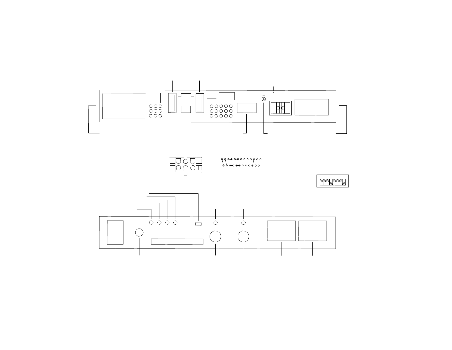
Figure 2-1
AREA
DO NOT OBSTRUCT
(14)
POSITIVE
OUTPUT
(8-80V MODELS)
(16)
NEGATIVE
OUTPUT
(8-80V MODELS)
REAR VIEW
SERIAL
NUMBER
J3
13
25
1
14
(18)
AC INPUT
CONNECTOR
115/230 VOLT
(SELECTABLE)
47-83 HZ,
NEUT, LINE
SORENSEN DCS SERIES MANUAL INSTALLATION and OPERATION
ALLOW ADEQUATE CLEARANCE
ON SIDE FOR VENTILATION
(7) OVER TEMPERATURE LED
(6) REMOTE PROGRAM LED
(5) SHUTDOWN LED
(4) OVP LED
(3) OVP ADJUST
POTENTIOMENTER
(1)
AC POWER
SWITCH
(2)
AC INPUT
BREAKER
(15)
OUTPUT AND
SENSE CONNECTOR
FOR 150, 300
AND 600V MODELS
(MATING CONNECTOR AND SOCKET PINS
SUPPLIED WITH EACH UNIT)
1
2
3
4
5
6
1 - POSITIVE SENSE
2 & 3 - POSITIVE OUTPUT
4 - NEGATIVE SENSE
5 & 6 - NEGATIVE OUTPUT
FRONT VIEW
(8)
VOLTAGE
MODE
LED
OUTPUT
VOLTAGE
CONTROL
PROGRAM, SENSE
J3 CONNECTIONS FOR
LOCAL OPERATIONS
13
25
(9)
(17)
AND MONITOR
CONNECTOR J3
(10)
CURRENT
MODE
LED
(11)
OUTPUT
CURRENT
CONTROL
(18)
AC INPUT
SAFETY GROUND
SCREW
1
14
(12)
DIGITAL
VOLTMETER
ALLOW ADEQUATE CLEARANCE
ON SIDE FOR VENTILATION
SWITCH SW1
PROGRAMMING RANGE SELECTOR
MOUNTED INTERNALLY ON MAIN PCB
SWITCHES SHOWN SET FOR LOCAL OPERATION
1
2
3
45678
(13)
DIGITAL
AMMETER
OFF (OPEN)
ON (CLOSED)
2-3

INSTALLATION and OPERATION SORENSEN DCS SERIES MANUAL
CONNECTOR J3
25114
2.4 Initial Functional Tests
Before connecting the unit to an AC outlet, make sure that the power switch is in the OFF position and that the
voltage and current controls are turned fully counter clockwise. Check that the J3 mating connector on the rear of
the unit is in place with jumpers connected for local operation as shown below. (This is the default configuration
as shipped from the factory). Connect the unit to a 230Vac grounded outlet (115Vac outlet if previously
configured for 115Vac operation as per instructions in section 2.3.1) and switch the unit on. After a short power
on delay the front panel meters should light up with both displays reading zero.
13
Connector J3 Configuration for Local Operation
To check voltage mode operation, proceed as follows:
• Connect a DVM, rated better than 0.5% accuracy, to the rear output terminals, observing correct
polarity.
• Rotate the CURRENT control 1/2 turn clockwise. Slowly rotate the VOLTAGE control clockwise and
observe both the internal and external meters. Minimum control range should be from zero to the
maximum rated output. Compare the test meter reading with the front panel voltmeter reading.
Check that the green voltage mode indicator led is ON.
• Set the POWER switch to OFF.
To check current mode operation, proceed as follows:
• Rotate the VOLTAGE and CURRENT controls fully counterclockwise.
• Rotate the VOLTAGE control 1/2 turn clockwise.
• Connect a high current DC ammeter across the rear output terminals, observing correct polarity.
Select leads of sufficient current carrying capacity and an ammeter range compatible with the unit's
rated current output. The ammeter should have an accuracy of better than 0.5%.
• Set the POWER switch to ON.
• Rotate the CURRENT control slowly clockwise. The control range should be from zero to the
maximum rated output. Compare the test meter reading with the reading on the front panel ammeter.
Check that the red current mode indicator led is ON.
• Set the POWER switch to OFF.
2-4

SORENSEN DCS SERIES MANUAL INSTALLATION and OPERATION
2.5 Controls, Connectors, and Indicators
Refer to Figure 2-1 and the descriptions below.
2.5.1 Front Panel
1. AC Power Switch
2. AC Input Circuit Breaker
3. OVP Adjust Potentiometer: Manual adjustment for OVP trip level
4. OVP LED: Indicates that the OVP circuit has been activated when illuminated
5. Shutdown LED: Indicates activation of the remote shutdown circuit when illuminated
6. Remote Programming LED: Indicates operation by remote programming when illuminated
7. Over-Temperature LED: Indicates that the power supply is shut down due to an internal overtemperature condition when illuminated
8. Voltage Mode LED: Indicates operation in voltage mode when illuminated
9. Output Voltage Control: Multi-turn potentiometer used to adjust the output voltage in local mode
10. Current Mode LED: Indicates operation in current mode when illuminated
11. Output Current Control: Multi-turn potentiometer used to adjust the output current limit in local
mode
12. Digital Voltmeter
13. Digital Ammeter
2.5.2 Rear Panel
14. Positive Output for 8, 20, 33, 40, 50, 60, and 80 Volt Models
15. Output and Sense Connector for 150, 300 and 600 Volt Models
16. Negative Output for 8, 20, 33, 40, 50, 60, and 80 Volt Models
17. Programming, Sense and Monitor Connector J3: Input connector for programming signals. Also
provides access to sense connections and monitoring points. See Table 2-1 for individual pin
descriptions. Note: The positive output and positive sense are not available at connector J3 on 150,
300 and 600 volt models
18. AC Input Safety Ground Screw
19. AC Input Connector
2-5

INSTALLATION and OPERATION SORENSEN DCS SERIES MANUAL
Table 2-1 J3 Program, Sense and Monitor Connector Description
(D-subminiature 25 Pin Female) *
PIN NUMBER FUNCTION
1............. AC/DC Shutdown Input (12-250Vac or 12-130Vdc)
14 TTL Shutdown Input
2............. Return for Shutdown Input Signals
15 +12Vdc Output (1k ohm source impedance)
3............. OVP Programming Input (0-5V, 0-10V or 0-1mA)
Jumpered to pin 16 for local mode operation
16 1mA Current Source for Local OVP Control or
Remote Resistive OVP Programming
4............. Remote Programming Indicator
High = Remote Programming Low = Local Control
17 OVP Status (High = OVP Circuit Activated)
5............. Operating Mode Indicator
High = Voltage Mode Low = Current Mode
18 Thermal Shutdown Indicator (High = Shutdown)
6............. Ground
19 Output Voltage Monitor (Uncalibrated) 0-5V = 0-100%
7............. Output Current Monitor (Calibrated) 0-5V = 0-100%
20 Front Panel Voltage Control (Local Mode)
Jumpered to pin 21 for local operation
8............. Front Panel Voltage Control (Remote Programming)
Input for 0-1mA remote programming signal
Jumpered to pin 9 for local operation and
remote current source programming
21 1mA Current Source for Local Operation or
Remote Resistive Programming of Output Voltage
Jumpered to pin 20 for local operation
9............. Remote Voltage Programming Input (0-5V or 0-10V)
Jumpered to pin 8 for local operation and
remote current source programming
22 1mA Current Source for Local Operation or
Remote Resistive Programming of Output Current Limit
Jumpered to pin 23 for local operation
10............ Remote Current Programming Input (0-100mV, 0-5V or 0-10V)
Jumpered to pin 11 for local operation and
remote current source programming
23 Front Panel Current Control (Local Mode)
Jumpered to pin 22 for local operation
11............ Front Panel Current Control (Remote Programming)
Input for 0-1mA external programming signal
Jumpered to pin 10 for local operation and
remote current source programming
24 Return (for local sense connections only)
12............ Return Sense (Return for Remote Programming Inputs)
25 Positive Output (for local sense connections only)
13............ Positive Sense
Note: Pins 25 and 13 not connected on 150, 300 and 600V models.
* Mating connector - 25 pin male ITT Cannon DB25P or equivalent.
2-6
 Loading...