

Page 1
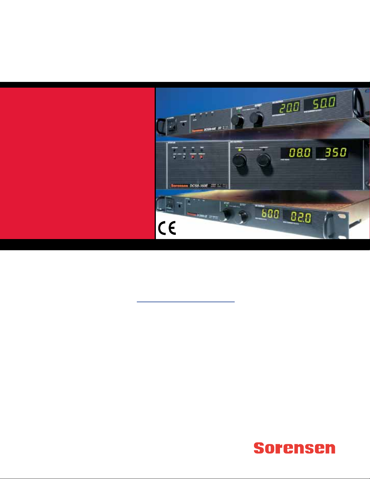
T
he DCS Family of 1 kW, 1.2 kW and
3 kW programmable power supplies utilize switching-mode technology to achieve high power density in a
low profile chassis. Utilizing unique
packaging techniques, the DCS Family
provides continuous full output power
(1 kW, 1.2 kW or 3 kW) in any volt/
amp combination within the rated
output voltage and current limits.
This family has 10-turn potentiometers
to adjust voltage and current settings
that are displayed simultaneously.
LEDs indicate overtemperature,remote
programming, shutdown and overvoltage protection, status and constantvoltage/current mode operation.
The DCS 3 kW Models have push button control of the output via standby
mode, OVP reset, remote/ local programming and preview status of voltage, current and OVP setpoints.
• Regulation
• Line regulation: 0.1%
• Load regulation: 0.1%
• Remote Programming
• Selectable remote programming for voltage, current and
OVP
• Optional internal IEEE-488/
RS 232 Interface Card with
voltage and current readback and
adjustable OVP (Option M9C)
•Optional multichannel slave
interface (Option M85)
•Optional isolated analog
programming (Option M51A)
• Software
•LabVIEW® driver for M9C/M85 can
be downloaded at no cost at
www.elgar.com
• Regulatory Compliance
•CE Mark on all models, FCC Part
15 Class Aand CSA 22.2 #220 (1
and 1.2 kW only)
• 5 Year Warranty
DC Programmable Switching Supplies
DCS Series
DCS Applications
The DCS Family is ideally suited
for a wide range of applications
requiring DC power in a small form
factor. Applications range from
manufacturing test of automotive
components, telecommunications
products and avionics to beam
steering, process control and
laboratory R&D use.
Key Features
• Output Voltage
Voltage ranges from 0-8 VDC to 0600 VDC; current levels from 1.7A to
350A
• Power Density
• 1 kW or 1.2 kW of power in a
19 lb. package only 1.75 inches
high
• 3 kW of power in a 33 lb.
package only 3.5 inches high
• Input Voltage
• 1 kW or 1.2 kW: 100-132 VAC,
single phase, or 200-250 VAC,
single phase 47-63 Hz
• 3 kW: 190-250 VAC, three
phase or 200-250 VAC, single
phase 47-63 Hz (2.5 kW max
with single phase input
Options include an internal IEEE488/RS 232 interface, isolated analog
programming of voltage and current,
and the multichannel slave interface
(Option M85).
1 kW, 1.2 kW, & 3 kW
Page 2

Output
Voltage and Current
1 kW Model Voltage Current
DCS 8-125E 0-8 0-125
DCS 10-100E 0-10 0-100
DCS 20-50E 0-20 0-50
DCS 33-33E 0-33 0-33
DCS 40-25E 0-40 0-25
DCS 50-20E 0-50 0-20
DCS 60-18E 0-60 0-18
DCS 80-13E 0-80 0-13
DCS 100-10E 0-100 0-10
DCS 150-7E 0-150 0-7
DCS 300-3.5E 0-300 0-3.5
DCS 600-1.7E 0-600 0-1.7
1.2 kW Model Voltage Current
DCS 8-140E 0-8 0-140
DCS 10-120E 0-10 0-120
DCS 20-60E 0-20 0-60
DCS 33-36E 0-30 0-36
DCS 40-30E 0-40 0-30
DCS 50-24E 0-50 0-24
DCS 60-20E 0-60 0-20
DCS 80-15E 0-80 0-15
DCS 100-12E 0-100 0-12
DCS 150-8E 0-150 0-8
DCS 300-4E 0-300 0-4
DCS 600-2E 0-600 0-2
3 kW Model Voltage Current
DCS 8-350E 0-8 0-350
DCS 12-250E 0-12 0-250
DCS 20-150E 0-20 0-150
DCS 40-75E 0-40 0-75
DCS 55-55E 0-55 0-55
DCS 60-50E 0-60 0-50
DCS 80-37E 0-80 0-37
DCS 150-20E 0-150 0-20
Voltage Resolution: 0.02%
Ripple (mV RMS or P-P): See table
Regulation (Line or Load)
V oltage:
0.1%
Current: 0.1%
Transient Response: Typically
recovers in 500 µs (1 & 1.2 kW) or
1ms (3k W) to 1% of steady-state output voltage (within 1% of Vmax) for
70-100% or 100-70% load change.
Stability: ±0.05% of maximum volt-
age or current over 8 hours after 30
minute warm-up time at fixed line,
load and temperature
Efficiency: See table
Temperature Coefficient: 0.02%/°C
of maximum output voltage; 0.03%/°C
of maximum output current
Input
Voltage and Frequency
1 kW:
200-250 VAC, single phase, 8A
typical, 47-63 Hz; or 100-132 VAC,
single phase, 15A typical, 47-63 Hz,
internal jumper selectable (see M1
option)
1.2 kW: 200-250 VAC, single phase,
9A typical, 47-63 Hz; or 100-132 VAC,
single phase, 18A typical, 47-63 Hz,
internal jumper selectable (see M1
option)
3 kW: 190-250 VAC, three phase, 14A
typical, 47-63 Hz; or 200-250 VAC,
single phase, 20A typical, 47-63 Hz
Note: Maximum power output of 3 kW
supplies must be limited to 2.5 kW for
single phase input
Soft Start: Line current is lower than
full load peak value during turn-on or
power application after restart
General
Operating Temperature: 0°C to
50°C (no derating), 50°C to 70°C
(derate 2%/°C above 50°C)
Storage Temperature: -55°C to
85°C
Humidity Range: 0 to 80% RH,
non condensing
Meter Accuracy: 1% of full scale +
1 count
Max. Voltage Differential from
Output to Safety Ground: 150 VDC
Remote Start/Stop and Interlock:
TTL compatible input or 12-250 VAC
(12-130 VDC) or a contact closure
Cooling: Internal fan, overtempera-
ture shutdown if internal heat sink
exceeeds set temperature
Remote Sense: The maximum
allowed sense line drop is 4V per line
(2V on the DCS 8 and 10V 1kW and
1.2 kW models and 1V/line for all 3
kw models)
Remote Programming: External
jumper via rear panel connector J3
Overvoltage Protection: Crowbar
type adjustable from 5-110% of rated
output using front panel control
(local or remote program selectable
via J3 jumper)
Remote Analog Programming
Linearity: ±1%
Accuracy: ±5%
Software: LabVIEW® driver for
M9C/M85 can be downloaded at no
cost at www.elgar.com.
Regulatory Compliance: CE Mark
(1, 1.2, 3k W); FCC Part 15 Class A,
UL1012, CSA 22.2 #220 (1 and 1.2
kW only)
Dimensions
1 kW and 1.2 kW: 1U or 1.75”
(44 mm) H x 19” (482 mm) W x
17.5” (444 mm) D
3 kW: 2U or 3.5” (88 mm) H x
19” (482 mm) W x 17.5”
(444 mm) D
Weight
1 kW and 1.2 kW: 19 lbs. ( 8.6 kg)
3 kW: 33 lbs. (15 kg)
Shipping Weight
1 kW and 1.2 kW: 24 lbs. (10.9 kg)
3 kW: 42 lbs. (19 kg)
Options & Accessories
M1: Factory configured for 115 VAC
input (1 kW and 1.2 kW units only)
M9C: Internal IEEE-488/RS 232
Interface
M13: Locking shafts (front panel
potentiometers)
M32: Master/slave paralleling cable
configured for two units
M33: Replace input connector with
terminal block (3 kW only)
M51A: Isolated analog programming
control of V/I/OVP and isolated V/I
monitor outputs up to 500V relative to
the supply’s return line
M85: Multichannel slave interface
allows use of a single GPIB address
(using 1 master unit with M9C
option) to control multiple units via a
standard RS485 connector (3 ft.
connector included)
Page 3
DCS 1 kW
Programming Constants
Voltage Mode
Ohms/V V/V
Model
Output Power
VDC
Current
@ 50°C
Voltage
ADC
Combined
Regulation
Line and
Load %
Constant Voltage Mode*
Ripple
(RMS)**
Noise
(P-P)
Transient
Response
Time
µs (Typ)
Temp. Coeff.
Voltage
%/°C (Typ)
Voltage
Drift
% Vmax
(Typ)
DCS 8-125E 0-8 0-125 0.2 4 mV 60 mV 500 0.02 0.05 625
DCS 10-100E 0-10 0-100 0.2 4 mV 60 mV 500 0.02 0.05 500
DCS 20-50E 0-20 0-50 0.2 4 mV 60 mV 500 0.02 0.05 250
DCS 33-33E 0-33 0-33 0.2 4 mV 60 mV 500 0.02 0.05 151.5
DCS 40-25E 0-40 0-25 0.2 4 mV 60 mV 500 0.02 0.05 125
DCS 50-20E 0-50 0-20 0.2 4 mV 60 mV 500 0.02 0.05 100
DCS 60-18E 0-60 0-18 0.2 4 mV 60 mV 500 0.02 0.05 83
DCS 80-13E 0-80 0-13 0.2 4 mV 60 mV 500 0.02 0.05 62.5
DCS 100-10E 0-100 0-10 0.2 6 mV 60 mV 500
0.02 0.05 50
DCS 150-7E 0-150 0-7 0.2 12 mV 160 mV 500 0.02 0.05 33.3
0-10V =
0-100% V
or
0-5V =
0-100% V
0
0
DCS 300-3.5E 0-300 0-3.5 0.2 20 mV 200 mV 500 0.02 0.05 16.67
DCS 600-1.7E 0-600 0-1.7 *** *** *** *** *** *** ***
Programming
Model
Constant Current Mode*
Regulation
Line and Load
% Combined
Ripple
(RMS)**
mA
Temp.
Coeff.
%/°C
(Typ.)
Current
Drift
%I0Max.
(Typ.)
DCS 8-125E 0.2 160 0.03 0.05 40 8 N/A
Constants, Current
Mode
Ohms/A V/A
Input Current, A Nominal
230V Single
Phase
208V Three
Phase
Efficiency %
(Typ.)
82
Case
DCS 10-100E 0.2 128 0.03 0.05 50 8 N/A 82 I
DCS 20-50E 0.2 25 0.03 0.05 100 8 N/A
DCS 33-33E 0.2 10 0.03 0.05 151.5 8 N/A
DCS 40-25E 0.2 7 0.03 0.05 200 8 N/A
82
84
84
0-10V=
DCS 50-20E 0.2 I7 0.03 0.05 250 8 N/A 84
0-100% I
0
or
DCS 60-18E 0.2 6 0.03 0.05 277.8 8 N/A
0-5V=
0-100% I
86
0
DCS 80-13E 0.2 4 0.03 0.05 384.6 8 N/A 86 I
I
I
I
I
I
DCS 100-10E
0.2 3 0.03 0.05 500 8 N/A 86 I
DCS 150-7E 0.2 2 0.03 0.05 714.3 8 N/A 86 I
DCS 300-3.5E 0.2 1 0.03 0.05 1428.6 8 N/A 86 I
DCS 600-1.7E
* Typical resolution is 0.02% ** RMS ripple typical from 20 Hz to 300 kHz ***Consult factory
*** *** *** *** *** *** *** *** ***
Page 4
DCS 1.2 kW
Programming Constants
Voltage Mode
Ohms/V V/V
Model
Output Power
VDC
Current
@ 50°C
Voltage
ADC
Combined
Regulation
Line and
Load %
Constant Voltage Mode*
Ripple
(RMS)**
Noise
(P-P)
Transient
Response
Time
µs (Typ)
Temp. Coeff.
Voltage
%/°C (Typ)
Voltage
Drift
% Vmax
(Typ)
DCS 8-140E 0-8 0-140 0.2 5 mV 60 mV 500 0.02 0.05 625
DCS 10-120E 0-10 0-120 0.2 5 mV 60 mV 500 0.02 0.05 500
DCS 20-60E 0-20 0-60 0.2 5 mV 60 mV 500 0.02 0.05 250
DCS 33-36E 0-33 0-36 0.2 5 mV 60 mV 500 0.02 0.05 151.5
DCS 40-30E 0-40 0-30 0.2 5 mV 60 mV 500 0.02 0.05 125
DCS 50-24E 0-50 0-24 0.2 5 mV 60 mV 500 0.02 0.05 100
DCS 60-20E 0-60 0-20 0.2 5 mV 60 mV 500 0.02 0.05 83
DCS 80-15E 0-80 0-15 0.2 5 mV 60 mV 500 0.02 0.05 62.5
DCS 100-12E 0-100 0-12 0.2 10 mV 60 mV 500 0.02 0.05 50
DCS 150-8E 0-150 0-8 0.2 15 mV 160 mV 500 0.02 0.05 33.3
0-10V=
0-100% V
or
0-5V=
0-100% V
0
0
DCS 300-4E 0-300 0-4 0.2 25 mV 200 mV 500 0.02 0.05 16.67
DCS 600-2E 0-600 0-2 *** *** *** *** *** *** ***
Programming
Constants, Current
Mode
Ohms/A V/A
Input Current, A Nominal
230V Single
Phase
208V Three
Phase
Efficiency %
(Typ.)
82
82
Case
Model
Constant Current Mode*
Regulation
Line and Load
% Combined
Ripple
(RMS)**
mA
Temp.
Coeff.
%/°C
(Typ.)
Current
Drift
%I0Max.
(Typ.)
DCS 8-140E 0.2 180 0.03 0.05 35.7 9 N/A
DCS 10-120E 0.2 153 0.03 0.05 41.7 9 N/A
DCS 20-60E 0.2 30 0.03 0.05 83.3 9 N/A 82 I
DCS 33-36E 0.2 11 0.03 0.05 138.9 9 N/A
DCS 40-30E 0.2 9 0.03 0.05 166.7 9 N/A
84
84
0-10V=
DCS 50-24E 0.2 8.5 0.03 0.05 208.3 9 N/A
0-100% I
0
84
or
DCS 60-20E 0.2 6.6 0.03 0.05 250.0 9 N/A
DCS 80-15E 0.2 6 0.03 0.05 333.3 9 N/A
0-5V=
0-100% I
85
0
85
I
I
I
I
I
I
I
DCS 100-12E 0.2 3.6 0.03 0.05 416.7 9 N/A
85
DCS 150-8E 0.2 I2.3 0.03 0.05 625.0 9 N/A 85
DCS 300-4E 0.2 1.2 0.03 0.05 1250.0 9 N/A
DCS 600-2E *** *** *** *** *** *** ***
* Typical resolution is 0.02% ** RMS ripple typical from 20 Hz to 300 kHz *** Consult factory
85
***
I
I
***
Page 5
DCS 3 kW
Constant
Programming Constants
Voltage Mode
Ohms/V V/V
Model
Output Power
Voltage
VDC
Current
ADC
@ 50°C
Combined
Regulation
Line and
Load %
Constant Voltage Mode*
Ripple
(RMS)**
Noise
(P-P)
Transient
Response
Time
µs (Typ)
Temp. Coeff.
Voltage
%/°C (Typ)
Voltage
Drift
% Vmax
(Typ)
DCS 8-350E 0-8 0-350 0.2 15 mV 100 mV 1000 0.02 0.05 625
DCS 12-250E 0-12 0-250 0.2 10 mV 100 mV 1000 0.02 0.05 416.7
DCS 20-150E 0-20 0-150 0.2 10 mV 100 mV 1000 0.02 0.05 250
DCS 40-75E 0-40 0-75 0.2 20 mV 100 mV 1000 0.02 0.05 125
DCS 55-55E 0-55 0-55 0.2 20 mV 100 mV 1000 0.02 0.05 90.9
DCS 60-50E 0-60 0-50 0.2 20 mV 100 mV 1000 0.02 0.05 83
DCS 80-37E 0-80 0-37 0.2 20 mV 100 mV 1000 0.02 0.05 62.5
DCS 150-20E 0-150 0-20 0.2 30 mV 200 mV 1000 0.02 0.05 33.3
Programming
ModelModel
Constant Current Mode*
Regulation
Line and Load
% Combined
Ripple
(RMS)**
mA
Temp.
Coeff.
%/°C
(Typ.)
Current
Drift
%I0Max.
(Typ.)
Constants, Current
Mode
Ohms/A V/A
Input Current, ANominal
230V Single
Phase
208V Three
Phase
Efficiency %
(Typ.)
0-10V=
0-100% V
or
0-5V=
0-100% V
Case
0
0
DCS 8-350E 0.2 870 0.03 0.05 14.3 24 13
DCS 12-250E 0.2 400 0.03 0.05 20 26 14
DCS 20-150E 0.2 100 0.03 0.05 33.3 26 14
82
82
82
0-10V=
DCS 40-75E 0.2 75 0.03 0.05 66.7 26 14
0-100% I
0
86
or
DCS 55-55E 0.2 40 0.03 0.05 90.9 26 14
DCS 60-50E 0.2 33 0.03 0.05 100 26 14
0-5V=
0-100% I
82
0
86 II
DCS 80-37E 0.2 20 0.03 0.05 135 26 14 86 II
DCS 150-20E 0.2 10 0.03 0.05 250 26 14 86 II
* Typical resolution is 0.02% ** RMS ripple typical from 20 Hz to 300 kHz
II
II
II
II
II
Page 6
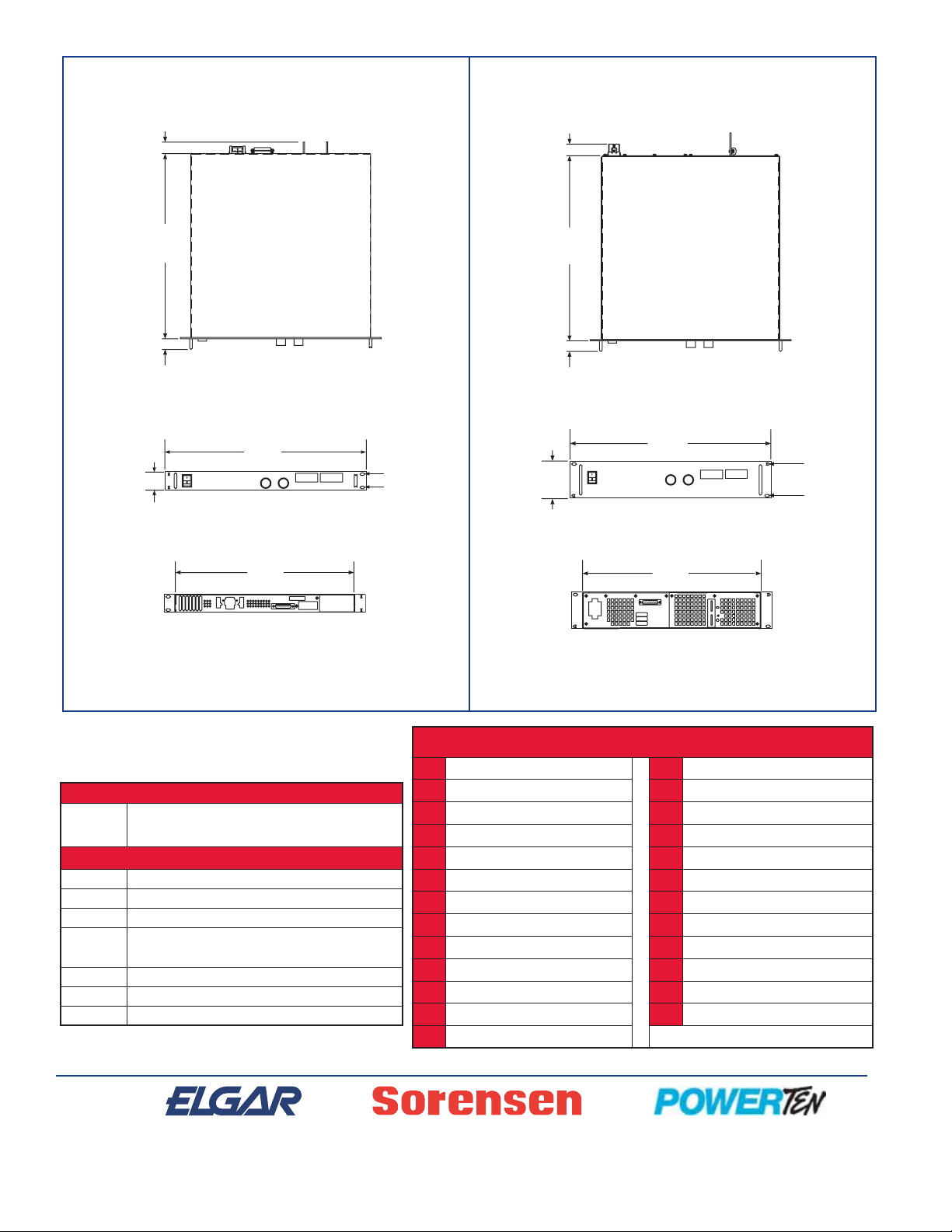
Top View
Front View
Dimensions in inches (millimeters)
Options & Accessories
Rear View
Case I
1.10
17.52
1.00
(28)
(445)
(25)
Top View
Front View
Rear View
Case II
1.10
(28)
17.52
(445)
1.00
(25)
19.00
(482)
1.72
(43)
16.90
(429)
Input Voltage Options
M1
Remote Interface Options
M9C Internal IEEE-488/RS 232 interface
M13 Locking shafts (front panel potentiometers)
M32 Master/slave cable configured for two or more units
M33
M51A Isolated analog programming control
M85 Multichannel slave interface
105-330-26 Rack slide kit (3 kW only)
Factory configured for 115 VAC input (1 and 1.2 kW
only)
Replace input connector with terminal block
(3 kW only)
1.25
(32)
3.46
(87)
J3 Program and Sense
1 90-250 VAC Remote Shutdown 14
2
Shutdown Return
OVP Program 1 mACurrent Source (OVP)
3
Remote/Local Status Indicator
4
5
Mode Status Indicator
6
Ground 19 0-5V Voltage Monitor
7
0-5V Current Monitor
Voltage Control
8
9
Voltage Program Input 22 1 mACurrent Source (I)
10
Current Program Unit 23 Remote Current Select
11
Current Control 24 Return
12
Return Sense
13 POS Sense (8-100V Models Only)
19.00
(482)
3.00
(76)
16.90
(429)
TTL Shutdown
15 +12 VDC
16
17 OVP Indicator
18 Thermal S/DN Status
20 Remote Voltage Select
21 1 mACurrent Source (V)
25 POS Output (8-100V Models Only)
 Loading...