

Page 1
Service Manual
for the
DIGORA
Production versions 01 – 04
NOTE: This manual is not a stand-alone manual and must be read
together with the User’s Manual of DIGORA Optime.
Service Manual for the DIGORATM Optime DXR-50 000
Document number 8201053 rev. 5 (2015-09) English
Copyright © 2014 by SOREDEX. All rights reserved
SOREDEXTM/DIGORATM are registered trademarks of SOREDEX, Palodex Group Oy.
Documentation, trademark and the software are copyrighted with all rights
reserved. Under the copyright laws the documentation may not be copied,
photocopied, reproduced, translated, or reduced to any electronic medium or
machine readable form in whole or part, without the prior written permission of
SOREDEX.
SOREDEX reserves the right to make changes in specification and features
shown herein, or discontinue the product described at any time without notice or
obligation.
Contact your SOREDEX representative for the most current information.
Manufacturer
techsupp@soredex.com orders@soredex.com www.soredex.com
SOREDEX, Palodex Group Oy
Nahkelantie 160
FI-04300 Tuusula, FINLAND
Tel. +358 10 270 2000
Optime DXR-50 000
TM
Page 2

TABLE OF CONTENTS,
DIGORA Optime DXR-50 000 Service manual
1. INTRODUCTION................................................................................................................. 6
D
ISCLAIMER
S
COPE
A
CRONYMS USED IN THIS MANUAL
................................................................................................................................. 6
.......................................................................................................................................... 6
.............................................................................................. 6
2. FIRMWARE: SYSTEM ARCHITECTURE ..................................................................... 7
O
PTIME CONNECTORS, KEYS AND INDICATOR
LED:S ................................................................... 8
3. INSTALLING AND SET-UP............................................................................................... 9
R
ECOMMENDED HARDWARE AT INSTALLATION
PRE-
INSTALLATION REQUIREMENTS
EMI –
I
INTERFERENCE, VIBRATION AND OPERATION WITH
NSTALLATION TROUBLESHOOTING
............................................................................................. 9
............................................................................................ 10
........................................................................... 9
UPS .................................................... 9
4. SERVICE TERMINAL ...................................................................................................... 11
A
CCESSING SERVICE TERMINAL
N
ORMAL AND SERVICE MODE OF THE UNIT
S
ERVICE COMMAND PRINCIPLES
S
ERVICE LOG
R
ECOMMENDED SERVICE COMMANDS ON FIELD SERVICE
............................................................................................................................. 14
................................................................................................ 11
............................................................................... 13
................................................................................................ 13
........................................................... 15
5. HARDWARE: LOCATION OF UNIT COMPONENTS ............................................... 17
C
OVERS AND SUPPORT STRUCTURE
L
OCATION OF MAIN PARTS AND COMPONENTS
............................................................................................ 17
........................................................................... 18
6. UNIT STATUSES AND MODES ...................................................................................... 19
7. HARDWARE: ELECTRONICS ....................................................................................... 20
R2000 E
R2100 P
R2200 P
R2300 I/O I
R2400 C
R2500 H
R2600 C
R2700 L
XTERNAL POWER SUPPLY UNIT
OWER & ANALOG BOARD
ROCESSOR BOARD
NTERFACE BOARD
ONNECTOR PANEL BOARD
IGH VOLTAGE CONNECTOR BOARD
ONTROL PANEL
ASER DETECTOR BOARD
........................................................................................................ 21
................................................................................................... 21
............................................................................................................ 22
............................................................................................... 22
................................................................................... 20
............................................................................................ 20
............................................................................................ 22
............................................................................. 22
8. FIELD SERVICE PROCEDURES ................................................................................... 23
S
ERVICE POLICY
R
EPLACEABLE PARTS / AVAILABLE SPARE PARTS FOR FIELD SERVICE
R
EMOVING THE COVERS
A
SSEMBLING THE COVERS
C
ALIBRATIONS ON FIELD SERVICE
:........................................................................................................................ 23
: ....................................... 23
............................................................................................................ 24
......................................................................................................... 25
.............................................................................................. 26
Calibrating (=optimizing) the plate carrier inserting position, <calpr position> ......... 26
Calibrating the Reflective Sensor (=plate detector) ...................................................... 26
Calibrating Resonant Scanner Amplitude ...................................................................... 27
Gear ratio calibration, from Firmware ver. 0.57. Command <gear> ................................. 28
A
DJUSTING THE PLATE CARRIER ( <EJECT>, <LOAD> AND <START>
). .................................. 29
Plate carrier position for plate insertion and plate detection, command <load XXXX> .... 29
Digora Optime CLASSIC DXR-50 000 Service Manual 8201053 rev. 5 (2015-09) 2 (87)
Page 3

Eject force, command <eject XXXX> ................................................................................... 29
Fine tuning the image position horizontally (LEFT - RIGHT), command <start XXXX> ... 29
Centering the image vertically, FINE TUNING (UP – DOWN) .......................................... 30
Centering the image vertically, COARSE ADJUSTMENT from serial nr. J501607 .......... 30
C
ONFIGURATION PARAMETERS
.................................................................................................. 31
Showing / setting configuration parameters (FS = factory setting) ..................................... 31
Autostart <autoscan> (FS 400, starts automatically 0,4sec after cover removal) ........... 31
Beeper (FS 1 = all beeps enabled) ................................................................................... 31
Standby mode <idle> (FS 600 seconds = unit waits 10 min before entering standby) ..... 31
Automatic shutdown <off> (FS 240 minutes = unit shuts down after 4hrs) ..................... 31
Restoring factory settings ..................................................................................................... 31
F
IRMWARE
F
IRMWARE
C
ORE UPGRADE
R
EPLACING EXTERNAL POWER SUPPLY
R
EPLACING
R
EPLACING
R
EPLACING
R
EPLACING
R
EPLACING
R
EPLACING REFLECTIVE SENSOR
R
EPLACING HOME OPTO SWITCH
R
EPLACING ERASING LAMP
R
EPLACING SAFETY SWITCH
R
EPLACING SAFETY SWITCH HOLDER
R
EPLACING COVERS
R
EPLACING SCANNER MODULE
D
RIVE BELT (GREY/BLACK): CLEANING, TENSION CHECK, ADJUSTMENT AND REPLACEMENT
P
LATE CARRIER BELT (CONVEYOR BELT): TENSION CHECK AND ADJUSTMENT
P
LATE CARRIER DRIVE MECHANISM: CLEANING AND LUBRICATING
M
AINTENANCE
(=FW)
(=FW)
AND CORE UPGRADING
UPGRADE
.................................................................................................... 33
............................................................................... 32
........................................................................................................................ 33
..................................................................................... 34
R2100 P
R2200 P
R2300 I/O I
R2400 C
R2600 C
OWER & ANALOG BOARD
ROCESSOR BOARD
NTERFACE BOARD
ONNECTOR PANEL BOARD
ONTROL PANEL
..................................................................................... 34
................................................................................ 34
......................................................................................... 35
......................................................................... 34
........................................................................ 35
.............................................................................................. 35
.............................................................................................. 35
....................................................................................................... 35
...................................................................................................... 36
........................................................................................ 36
................................................................................................................... 36
.................................................................................................. 36
........................... 38
........................................... 40
........................................................................................................................... 41
.... 37
9. DIAGNOSTICS / SELF DIAGNOSTICS ........................................................................ 43
ADC-
INPUT READING -TEST <DEBUG 9> ACTIVATED FROM SERVICE TERMINAL
A
UTOMATIC SELF –DIAGNOSTICS ON POWER-UP
S
ELF-DIAGNOSE TEST ACTIVATED FROM SERVICE TERMINAL
S
ELF-TEST
10.
11.
O
PERATING WARNINGS AND PRECAUTIONS
S
ERVICING PRECAUTIONS
(=E
NDURANCE TEST) ACTIVATED FROM SERVICE TERMINAL
BLOCK DIAGRAMS OF ELECTRONIC BOARDS ................................................. 45
WARNINGS AND PRECAUTIONS ............................................................................ 47
.......................................................................................................... 47
....................................................................... 43
............................................................................... 47
..................................................... 43
................................... 44
........................ 43
TROUBLESHOOTING DIGORA OPTIME DXR-50 000 .................................................... 48
TROUBLESHOOTING BY USING ERROR CODES ........................................................... 48
E
RROR
E
RROR
E
RROR
E
RROR
E
RROR
E
RROR
E
RROR
E
RROR
032 C
033 T
034 (35, 41 & 42) T
035 T
036 C
037 CRC
038 H
039 L
ARRIER HOME TOO EARLY (MAYBE STUCK DURING THE EJECT MOVEMENT
IMEOUT WHILE HOMING CARRIER
IMEOUT WHILE TRYING TO GET LASER SYNC
IMEOUT WHEN WAITING THE STABILIZING OF THE LASER SYNC
ONFIGURATION DATA INVALID
INVALID
IGH VOLTAGE NOT OK
OG AMP CALIBRATION FAILURE
........................................................................................................ 51
......................................................................................... 51
....................................................................... 49
............................................................................ 51
........................................................................... 52
) ..... 48
............................... 50
......................... 50
Digora Optime CLASSIC DXR-50 000 Service Manual 8201053 rev. 5 (2015-09) 3 (87)
Page 4

E
RROR
E
RROR
E
RROR
E
RROR
E
RROR
E
RROR
040 C
041 T
042 T
043 E
044 P
045 P
ARRIER UNABLE TO LEAVE HOME POSITION
IMEOUT WHILE TRYING TO GET LASER SYNC AVERAGES
IMEOUT WHILE TRYING TO GET LASER SYNC DURING SCAN
RASING LAMP BLOWN
LATE / REFLECTIVE SENSOR BROKEN (DETECTED DURING START UP
LATE / REFLECTIVE SENSOR BROKEN (CALIBRATION FAILURE
......................................................................................... 52
....................................................... 52
.................................... 52
............................... 52
) .............. 53
) .......................... 53
TROUBLESHOOTING WITHOUT ACTUAL ERROR CODE AVAILABLE ................. 54
E
RROR: DEGRADED IMAGE QUALITY –WARNING (IN APPLICATION
E
RROR: SHOWS COMPLETELY BLANK IMAGE
E
RROR: OPTIME “FREEZES
E
RROR: DOOR MECHANISM RELATED ERRORS
E
RROR: MAKING A “SQUEAKING” NOISE WHEN DOOR IS OPENING
E
RROR: NOT EJECTING PROPERLY / EJECT FORCE VARIES / CHANGING <EJECT
NOT SOLVE THE PROBLEM
E
RROR: UNIT FREEZING WHILE GOING TO ERROR MODE
E
RROR: NOT STARTING IMAGE READOUT WHEN THE PLATE IS INSERTED PROPERLY OR
S
TARTS READOUT WITHOUT THE PLATE OR STARTS READOUT PLATE WRONG WAY ROUND
E
RROR: NO RESPONSE WHILE A KEY IS PRESSED
E
RROR: CONTROL PANEL
E
RROR: UNIT STARTS UP BY ITSELF AFTER PLUGGING IN THE POWER CORD
E
RROR: UNIT GOES TO STANDBY-MODE BY ITSELF DURING OR AFTER STARTUP
” ...................................................................................................... 54
......................................................................................................... 55
LED:
S DIM, LIT CONSTANTLY OR NOT LIT AT ALL
........................................................................... 54
........................................................................ 54
......................................................... 55
.................................................................... 56
SW) .................................. 54
........................................... 54
XXXX>
DOES
... 55
............................ 56
.......................... 56
.................... 56
TROUBLESHOOTING BASED ON IMAGE ERRORS ....................................................... 57
I
MPROPER USE OF THE HYGIENE ACCESSORIES
I
MPROPER X-RAY SETTINGS USED
G
HOST IMAGES, SHADOWS
I
MPROPER AIMING OF THE X-RAY
U
NSHARP / BLURRED IMAGES
G
EOMETRY DISTORTION
D
ECREASED CONTRAST, SHADOWS/SHADING, GHOST IMAGES
W
HITE OR GREY DOTS/SPOTS/STAINS IN IMAGES
W
EARING OF THE IMAGING PLATES
I
MAGE SHOWS DIFFERENT SIZE THAN THE IP USED
C
IRCLE ON IMAGE
S
ERRATED IMAGE OR “SAWTOOTH” PATTERN
V
ERTICAL STRIPE(S
PMT
PROBLEMS
I
NCORRECT DIMENSIONS
...................................................................................................................... 59
) ................................................................................................................. 59
........................................................................................................................ 59
....................................................................................................... 57
........................................................................................................... 58
........................................................................................................... 59
............................................................................................ 57
............................................................................................. 57
................................................................................................... 58
.......................................................................................... 58
....................................................................... 57
… ............................................ 58
..................................................................... 58
.................................................................. 59
........................................................................... 59
APPENDIX 1: TROUBLESHOOTING ERRORS 035, 041 AND 042 – INSTRUCTIONS
FOR SCANNER MODULE REPLACEMENT AND CALIBRATION. .............................. 60
APPENDIX 2: SOLUTION FOR ERROR 039 LOG AMP CALIBRATION FAILURE ... 65
APPENDIX 3: SOLUTION FOR THE BLANK IMAGE, “DEGRADED IMAGE
QUALITY” AND “OPTIME FREEZING”. ............................................................................ 69
APPENDIX 4: INSTRUCTIONS HOW TO REPLACE R2200 PROCESSOR BOARD .. 70
APPENDIX 5: DOOR AND PLATE CARRIER MECHANISM MOVEMENT RELATED
PROBLEMS ................................................................................................................................ 71
APPENDIX 6: SERRATED IMAGE PROBLEM.................................................................. 73
APPENDIX 7: DIGORA OPTIME PMT FILTER LIGHT LEAK CHECK/REPAIR....... 74
APPENDIX 8: TEST AFTER REPAIR ................................................................................... 79
Digora Optime CLASSIC DXR-50 000 Service Manual 8201053 rev. 5 (2015-09) 4 (87)
Page 5

APPENDIX 9: DIGORA OPTIME HW, FW, CORE AND DRIVER VERSIONS, ............ 80
DIGORA
MODIFICATIONS
12.
13.
TM
OPTIME HARDWARE, FIRMWARE, CORE AND DRIVER VERSIONS +
......................................................................................................................... 80
CLASSIFICATION ........................................................................................................ 87
LABELING ..................................................................................................................... 87
Digora Optime CLASSIC DXR-50 000 Service Manual 8201053 rev. 5 (2015-09) 5 (87)
Page 6

1. Introduction
Disclaimer
Soredex endeavours to produce product documentation that is accurate and up to date.
However, our policy of continual product development may result in changes to products that
are not reflected in the product documentation. Therefore, this document should not be
regarded as an infallible guide to current product specifications. Soredex maintains the right to
make changes and alterations without prior notice.
Scope
This manual provides the information necessary to perform field servicing and maintaining of
the Digora Optime dental imaging scanner (hereafter referred as a `”unit”).
NOTE: This manual is not a stand-alone
manual and must be read together with the
User’s Manual of DIGORA
Only trained and approved service personnel of authorized distributors are allowed to
service the unit.
Unit can be sent to manufacturer for repair if it can not be repaired by:
• Performing the calibrations instructed in this manual AND
• Replacing field serviceable parts
TM
Optime.
Acronyms used in this manual
ADC Analog to Digital Converter
Cmd Command
DfW Application SoftWare (Digora for Windows, version 2.5 or newer)
DSD driver The driver used together with an imaging application
EMC ElectroMagnetic Compatibility
EMI ElectroMagnetic Interference
FW FirmWare of the unit
HV High Voltage
I/O Input/Output
IP Imaging Plate
IP address Internet Protocol Address, typically looks like 192.168.2.11
JXXXX Connector number
Msg Message
NIC Network Interface Card (installed on the computer Optime is connected to)
PMT Photo Multiplier Tube (=Photodetector)
PSU External Power Supply Unit
SW Imaging Application Software (DIGORATM for Windows, for example)
Digora Optime CLASSIC DXR-50 000 Service Manual 8201053 rev. 5 (2015-09) 6 (87)
Page 7
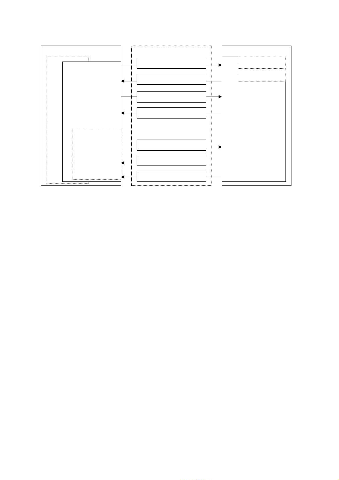
Scanner Firmware (FW)
Service Output Msg
Driver Cmd Msg
Image Data Msg
Image Data Req
uest Msg
User Cmd Reply Msg
User Cmd Msg
Driver Cmd Reply Msg
visible to user
2. Firmware: System Architecture
Workstation (PC)
Imaging Application (optional)
Driver
(mandatory)
All messages
invisible to the
user.
Ethernet
The unit (Optime)
Normal mode
Service mode
Service
Terminal
(optional)
All messages
Imaging Application (DfW 2.5 or newer)
• End user’s interface to acquired images.
• Handles image archiving and displaying.
Driver
• Handles the connection/communication to the unit
• Transfers and manipulates images.
• Unit cannot operate without Driver
There are two alternatives to be used as a driver:
1. DSD driver. Run from DfW (or other imaging application)
2. S2Terminal program. Run from the command prompt of Windows.
Service Terminal
• Optional part of the driver.
• Execute user commands
• View the service output of the unit.
There are two alternatives to be used as a Service terminal:
1. DSD driver. Run from Service Assistant of DfW (or other imaging application).
2. S2Terminal program. Run from the command prompt of Windows.
Scanner Firmware (=FW, Inside the connected unit)
• Takes care of the normal unit operations.
• Operates either in normal mode or service mode.
o Normal mode: Unit is fully operational and images can be acquired.
o Service mode: Unit does not react to any other inputs than those given by the user
through service terminal. To be activated only from Service Terminal.
• See operation flow chart (in Service Manual) for more detailed information on scanner
firmware operation.
Digora Optime CLASSIC DXR-50 000 Service Manual 8201053 rev. 5 (2015-09) 7 (87)
Page 8
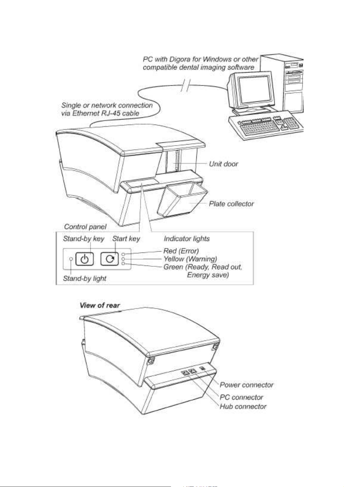
Optime connectors, keys and indicator LED:s
Digora Optime CLASSIC DXR-50 000 Service Manual 8201053 rev. 5 (2015-09) 8 (87)
Page 9

3. Installing and Set-up
Refer to installation manual for detailed installation instructions
Recommended hardware at installation
Following items help you to troubleshoot possible installation problems:
• Laptop-computer with:
o DfW 2.5 or above
o s2terminal.exe, s2.dll, W32N55.ini and W32N55.dll files copied to folder
c:\optimeservice
o Known working configuration with Optime
• RJ45 UTP network cable, known as working
• Switch 10/100mbs, known as working
Pre-installation requirements
• Digora Optime only works with the compatible imaging application software.
• DfW versions 2.5 or above support Digora Optime.
• Necessary drivers of the imaging application shall be installed also during software
installation. Refer to the DfW installation manual for more information.
• In order to connect to the network, a unique IP address for the unit is needed. Unique IP
can normally be inquired from the local network administrator.
• If several workstations are going to share the unit (multi-connection), determine which
workstations and workstation names will be used.
• Administrator privileges are needed to do the installation
• Multi-connection installation requires plenty of time compared to normal installation.
Arrange enough time.
• Make sure the PC(s) and the unit is correctly connected. Switch the unit on. Wait until
the self-test procedure has finished (this takes 15-60 s.) and make sure the unit
indicates the cables being properly connected.
• It is recommended to use network cards from the major brands; cheap generic cards
may cause problems. Here is a quick short list on recommended NIC-manufacturers:
o Intel (card or integrated onto motherboard), 3Com, Linksys, D-Link, Netgear…
installed
EMI –interference, vibration and operation with UPS
• Unit is tested as required by the medical device standards. However this testing does
not guarantee that the device is totally immune to all possible interferences.
• The heavy levels of EMI will disturb the imaging chain and so the scanner may reject the
calibration during the power-up or show as interference on the image.
• In addition to EMI also pure mechanical vibrations (even with small amplitudes) will
cause the same effect if the vibration frequency is in the certain range.
• One practical example of vibration origin is a computer reading CDROM (possibly a bit
out of balance) next to the unit.
If the unit is connected to the UPS (Uninterruptible Power System)
• Check that the UPS is classified as medical device and also check the manual if there
are any recommendations for its placement etc.
• The UPS may also generate mechanical vibrations at the frequency the unit is sensitive
to, so try to locate the UPS on the floor for example.
Digora Optime CLASSIC DXR-50 000 Service Manual 8201053 rev. 5 (2015-09) 9 (87)
Page 10

Installation troubleshooting
Optime is switched off or not correctly connected to the wall outlet.
Network cable connected to the wrong connector of Optime
• One is for a direct connection to the workstation PC / Other to the network
Defective RJ45 -cable
Incorrect/incompatible dsd.ocx or Optime firmware version
• If the IP-connection does not work, try with serial number connection and vice
versa.
Connection is ok, but images cannot be scanned
• Two or more workstations or clients connected simultaneously to same unit
• Command <clients> from the service terminal. Command output shows if there
are more than one client (=yourself) connected.
Problems on the local network
• Ask more information from the network administrator.
Subnet Configuration problem
• Conflict / mismatch IP-addresses and/or subnet mask of the Optime /
workstation.
• Command <ipconfig> in the Windows command prompt to get the information
about the active network settings
• Change unit or workstation IP address so that they both belong to same
subnet
• Ask more information from your network administrator.
Ethernet link not active
Physical Ethernet connection consists of correctly installed cabling and possible
switches and/or hubs. It is called shortly a ‘link’.
If the link is active, it does not necessarily mean the unit is physically connected to
correct workstation – it only means the unit is connected to an Ethernet
compatible environment (hub, switch, other computer etc). Possible problem
cases are:
• Physical connection is ok (=link active) but the unit is not configured correctly.
• Cabling not correct (=link not active, no physical connection between the
computer and Optime)
• Check that the workstation computer´s link is ok. There is usually a green link
led light visible near the Ethernet connector(s) of computer´s NIC.
• Detach and reconnect the Ethernet cable.
Digora Optime CLASSIC DXR-50 000 Service Manual 8201053 rev. 5 (2015-09) 10 (87)
Page 11

4. Service Terminal
Service terminal is a very useful service tool, but it is not an end user interface. Only trained
service technicians are allowed to use it. Wrong usage of the service terminal might change the
factory presets or damage the unit.
All service terminal commands and functions are not explained in this manual. Further
instructions can be read by connecting the unit to service terminal and using the service
terminal’s help command. This arrangement is to keep the documentation up to date, since the
service terminal instructions are always up-to-date inside the unit firmware.
Accessing Service Terminal
• Service commands are controlled either from DfW Service Assistant (light version
service tool) or S2terminal run from command prompt (complete service tool)
o Firmware and core upgrade can only be performed with S2terminal
o Scanora 3D does not have service assistant, operates only with S2terminal
NOTE: Only have either DfW (Service Assistant) OR S2terminal open at one time.
NOTE: DfW must be closed when accessing S2 terminal.
• S2 terminal software is started and operated from Windows command prompt.
o When the S2terminal is running, the title bar of the command prompt window
reads “s2terminal [ip-address]”
o When the S2terminal is closed, the title bar of the command prompt window
reads “cmd.exe”
Running the S2Terminal program needs the following files:
• s2terminal.exe (Must be version dated 22/05/2009 or later)
• s2.dll (Must be version dated 21/05/2009 or later)
•
W32N55.dll (Must be version dated 09/04/2008 or later)
•
W32N55.ini (Must be version dated 09/04/2008 or later)
•
(S2Terminal has to be version 3.2.127.0 or later)
1. Copy all above mentioned s2terminal files to one same and dedicated service folder
(in the following example “c:\s2terminal” folder is used to store s2terminal files)
2. Select from Windows: Start >> Programs >> Accessories >> Command Prompt
OR
Select from Windows: Start / run >> Type into “Open” -field: < cmd >
3. Choose OK
4. Using command prompt, go to the folder where Service Terminal files are located
(for example: cd C:\s2terminal)
Command prompt examples :
o <cd\> (Changes to the root directory =C:\)
o <cd s2terminal> (changes to directory “s2terminal”)
o <s2terminal> help for the s2terminal command syntax
5. CHECK THAT Application SW (DfW) IS CLOSED
6. Execute the program as follows:
<s2terminal 194.9.227.252> (Starts s2terminal for unit having ip 194.9.227.252)
OR
<s2terminal 192.168.2.11 –c> (Starts s2terminal and configures Optime ip to 192.168.2.11)
NOTE: Keep start button pressed when entering <s2terminal 192.168.2.11 –c>:
7. If the IP-address is correct and the s2terminal program is able to connect to the unit, it
prints out terminal output of the login command, which displays the following info:
“s2terminal, the unit’s firmware version(s), serial number and some parameters”.
Otherwise it displays an error message(s).
NOTE: It is normal that you may have few times “login fail (no connection)” –error
Digora Optime CLASSIC DXR-50 000 Service Manual 8201053 rev. 5 (2015-09) 11 (87)
Page 12

also in the beginning of normally functioning connection
8. Quit s2terminal program by <xq>
Digora Optime CLASSIC DXR-50 000 Service Manual 8201053 rev. 5 (2015-09) 12 (87)
Page 13

Access Service Terminal with DfW Service assistant (light version service tool)
• This is the alternative way to access service commands
o Can be used only if DfW –connection available
o Firmware download CAN NOT be performed by using this method
o Scanora 3D does not have Service assistant
• When DfW is connected, press CTRL+ALT+SHIFT+O simultaneously
>> Opens Digora Service Assistant
NOTE: If operating in Multiconnect configuration, the unit must be reserved first by pressing:
CTRL+ALT+SHIFT+O
Normal and Service Mode of the Unit
Service Terminal can be used having Optime in Normal mode or Service mode
• Normal mode = Normal operation, use Service Terminal to monitor the Optime operation
• Service mode = Optime Executes only the commands given from Service Terminal.
Most of the service procedures described in this manual is done in the service mode.
<s> Activates the service mode
If Optime is in standby mode, the first command only exits the standby mode
IF OPTIME IS NOT IN IDLE OR ERROR STATE, SERVICE MODE CAN NOT BE ENTERED.
IN THIS CASE YOU HAVE TO GET OPTIME INTO EITHER IDLE OR ERROR STATE.
ERROR STATE CAN BE ENTERED BY POWERING UP THE UNIT TOP COVER REMOVED
<quit> Quits the service mode (=resumes scanner into normal operation mode).
<reset> Resets Optime. After reset you exit also the service mode
Service Command principles
General Principles for Command Usage
• About half of the commands activate a function, for instance the movement of the plate
carrier or enabling the laser. The other half view or set the configuration parameters of
the unit.
• To use commands first see their description by <h [command]>.
NOTE: Do not execute the command if you are not sure about its function.
Improper use of some commands may damage the unit!
• When issuing the command without any value (for example <eject>) it will display the
current value of the parameter.
• If the parameter is followed with a value (for example <eject 12000>) the parameter
value is changed.
If the unit is in energy saving mode (=GREEN indicator flashing)
• Unit does not execute the command, but is exits the energy saving mode when the
command is entered for the first time
>> The same command has to be entered again to perform the required action.
Help Command
• The scanner firmware has built-in help for service commands.
• The help functionality is similar in both (Normal / Service) modes of the unit.
Digora Optime CLASSIC DXR-50 000 Service Manual 8201053 rev. 5 (2015-09) 13 (87)
Page 14

<h> Prints list of available commands
<h command> Typing h + any command followed by enter from the service terminal
>> shows the help for particular command.
Example <h calpr > shows the help for using calpr –options
<xh> s2terminal help menu
Service Command Syntax
<text> The text inside the brackets is typed in exactly as instructed +
followed by enter from the service terminal (unless other context is
specified in the clause)
Example <reset> means typing: reset (and pressing enter)
Example <idle> Shows the time unit waits before goes to standby
Example <idle XXX> Sets time (XXX seconds) unit waits before goes to standby
Configuration info
<conf> Shows the configuration parameters of the unit
Service Log
Service log is a very useful tool for troubleshooting, highly recommended for every field
technician!
• You can get list of the error messages, which helps on troubleshooting. (Every time an
error is caught it is recorded into the service log).
• You can see the performed service procedures
• Always start the service work by checking unit service log for error messages.
After the service work is done, sign the service log. Then it later displays what
service actions have been done for the unit.
TIP:
Copy the contents of the service log, paste it to Notepad and send to Soredex
Technical Support by Email. This helps SOREDEX to give troubleshooting support.
<h log> Shows the help for Service Log usage
<log> Shows the contents of Service Log after the latest service signature
<log all> Shows the whole contents of Service Log
<logsign> Signature =describe what kind of service you have performed.
Example: <logsign plate was not erased. John Smith replaced the erasing lamp>
>> saves “plate was not erased. John Smith replaced the erasing lamp”
to the service log
Digora Optime CLASSIC DXR-50 000 Service Manual 8201053 rev. 5 (2015-09) 14 (87)
Page 15

Recommended service commands on field service
Service commands may vary on different unit firmware versions.
Use always “online-help” of the service commands, they are up to date with the unit FW.
All service commands are not visible at service mode help menu, some of them are at
s2terminal help menu <xh>.
<s> Enters service mode (=Only service commands can be executed)
<autoscan 0> Configures Optime to start readout after START key is pressed
<autoscan 600> Configures Optime to start readout AUTOMATICALLY 0,6 seconds
after plate cover is removed (<autoscan XXX>, XXX =delay in
milliseconds)
<beeper 0> disables extra beeps (when going to idle mode etc…), but leaves all
error and warning beeps enabled
<beeper 1> Enables all beeps (including when going to idle mode etc…)
<log> Shows the contents of the service log after latest service signature
<logsign sensor calibrated> Stores “sensor calibrated” to service log
<log all> Shows whole contents of the service log
<cover> Shows status of top cover safety switch
<h> Shows list of available commands
<h calpr> Shows help for calpr -command. <h xxx> shows help for command,
which name is xxx. Help can be used for all commands.
_______________________________________________________________________
REFLECTIVE SENSOR CALIBRATION BEFORE SERIAL NUMBER J709614
<calpr position> Measures the optimum load position for the plate carrier
(=optimum carrier position for “no plate detection”, <calpr none>)
-Set recommended value by commanding <load XXXX>
-check plate ejecting performance after issuing <load XXXX>
(+adjust with <eject>, if necessary)
NOTE: PERFORM <calpr position> BEFORE <calpr>
<calpr none> calibrates reflective sensor,
<calpr black> see <h calpr> and chapter “Calibrating the reflective sensor
<calpr active
_______________________________________________________________________
REFLECTIVE SENSOR CALIBRATION FROM SERIAL NUMBER J709614
<calpr position> Measures and sets the optimum load position for the plate carrier
(=optimum carrier position for “no plate detection”)
See chapter “Calibrating the reflective sensor”
NOTE: PERFORM <calpr position> BEFORE <calpr>
<calpr all > Calibrates reflective sensor, follow on screen instructions
_______________________________________________________________________
<conf> Shows values of configuration parameters, (factory setting).
<debug 9> Drives the plate carrier in, activates high voltage and starts to
measure the ADC-input signal.
This test is very useful when troubleshooting certain hardware
(image signal) problems
Output value on the screen should be 0 (zero) when scanner door is
closed (the PMT does not see any light and electronics after it is OK)
/ increases if you open the scanner door manually
Digora Optime CLASSIC DXR-50 000 Service Manual 8201053 rev. 5 (2015-09) 15 (87)
Page 16

<debug 9> test is stopped with command <quit>
<home> Shows status of plate carrier home -optoswitch
<idle> Shows time (seconds) Optime waits before goes to energy-save
<idle XXX> Sets time (XXX seconds) Optime waits before goes to standby
<off> Shows time (minutes) Optime waits before automatic shut-down
<off XXX> Sets time (XXX minutes) before automatic shut-down
<plate> Shows reading of the plate detect reflective sensor
<test 5000 100> Makes Optime run self test 100 times with 5 sec. pause.
You can vary the parameters instead of 5000 and 100 as you wish.
<test> is not functioning in service mode!
<clients> Shows the ip-addresses of the client(s) connected to Optime
<quit> Exits service mode
<xq> Exits s2terminal –program (from command prompt of Windows)
<diagnose> performs self-diagnosis. Note that you have to press the Optime
keys.
<discard> discards the image from memory. If there is an un-transferred image
in unit memory, unit does not start to read new imaging plate and
does not respond pressing of any keys.
Commanding <discard> "releases" Unit for activity. does not delete
the image from memory, but sets the image information as like it
should have been transferred to computer.
<e> & <ec> Test the eject movement of the plate carrier
<eject> Sets the carrier movement length for plate ejecting
-increase the <eject> value if not properly ejected
-decrease the <eject> value if plates are go outside plate collector
<erase 1> / <erase 0> Switches erasing lamp on/off
<laser 1> / <laser 0> Switches laser on/off
<load> Sets the carrier position for plate feed
(Changing <load> may be needed if calpr fails)
<refltype> Show / set the type of reflective sensor. Default value is 1 from serial
number 709614. (=New type of sensor. Refltype = 0 before that)
<reset> resets Unit = Performs the normal initialization sequence.
Does not affect any parameter settings etc…
<restore configuration>
Restores the factory settings for all <conf> -parameters
Works only from Unit firmware 0.42.
<togglehv> disables high voltage
<togglehv> the 1. time = DISABLES High Voltage
<togglehv> the 2. time = ENABLES High Voltage
<togglehv> the 3. time = DISABLES High Voltage etc...
Restarting the unit will also restore normal operation.
<xq> Exits s2terminal –program (from command prompt of Windows)
Digora Optime CLASSIC DXR-50 000 Service Manual 8201053 rev. 5 (2015-09) 16 (87)
Page 17
screws
SLIDING J501607 >>
Panel
Collector
Panel Board
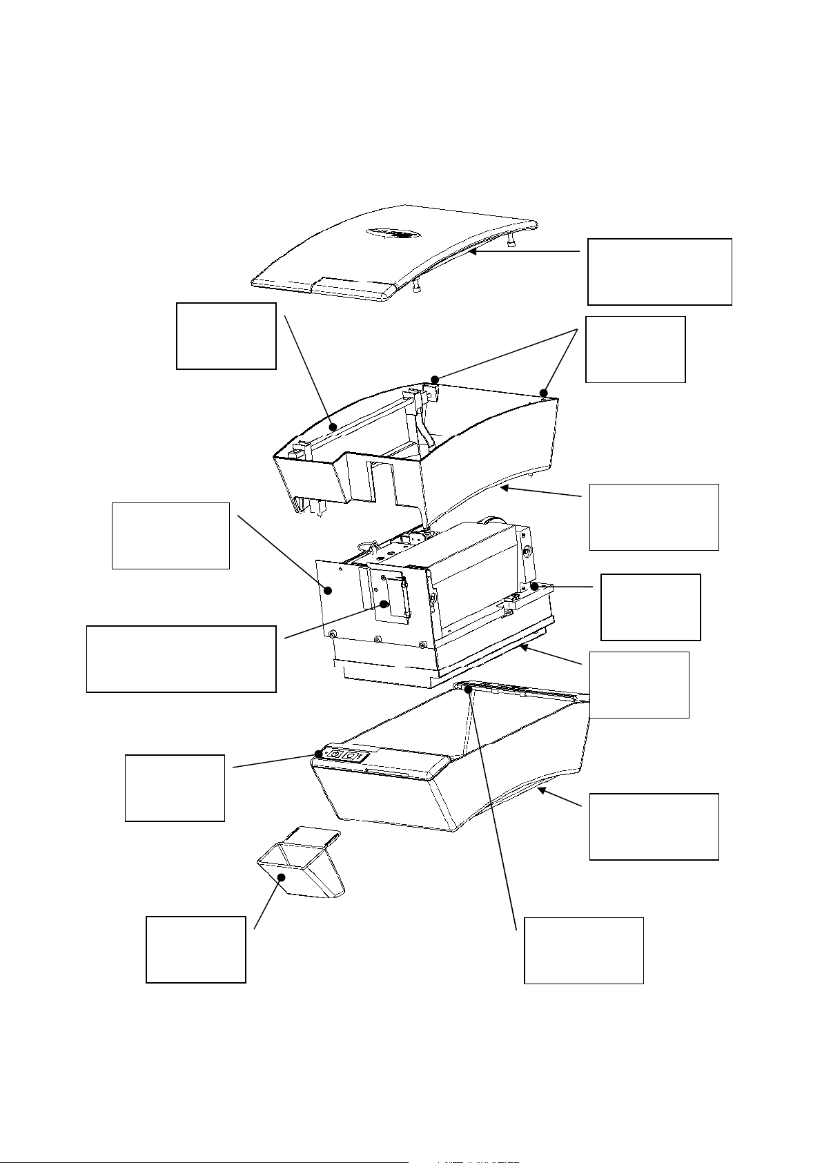
5. Hardware: Location of Unit Components
Covers and support structure
Refer to spare parts manual for item numbers.
Top Cover
(Upper cover, top)
Keyhole
locking bar
Front Plate
Unit Door
HINGED << J501606
Top Cover
releasing
Middle Cover
(Upper Cover)
Base Plate
Scanner
Mechanism
R2600
Control
Digora Optime CLASSIC DXR-50 000 Service Manual 8201053 rev. 5 (2015-09) 17 (87)
Imaging
Plate
Bottom Cover
(Lowest cover)
R2400
Connector
Page 18
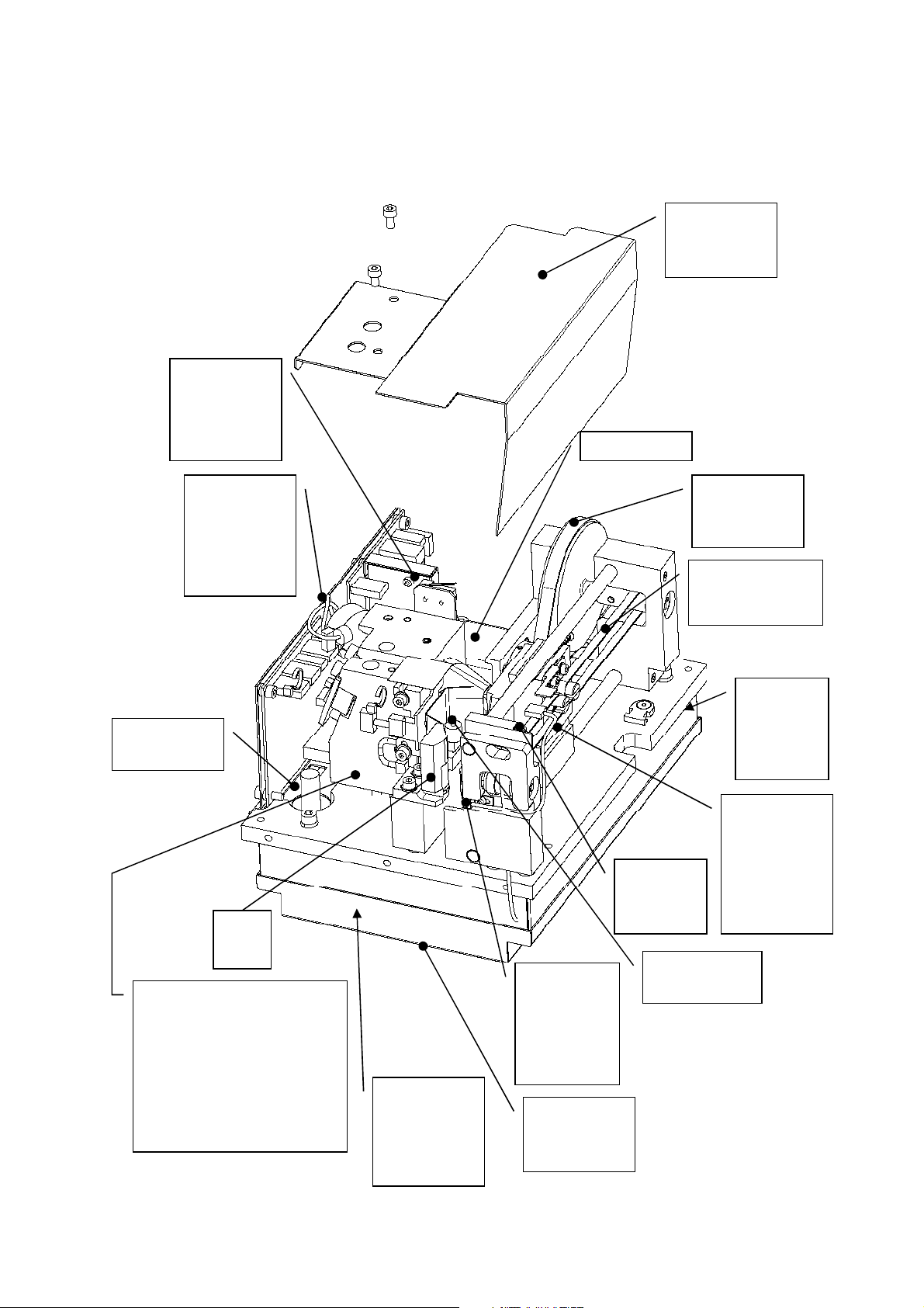
-
Mirror Scanner Assembly
Drive motor
Location of main parts and components
Refer to spare parts manual for item numbers.
R2000 External power supply not shown here.
Safety switch.
NOTE: Redesigned
holder from
J503179
Light
Protection
Cover
R2300 I/O
Interface
Board
NOTE:
New version
from J709614
BNC
Connector
Plate
guide
Scanner Module
(Readout trolley assembly)
Includes:
-Safety Switch
-R2700 Laser Detector Board
-PMT
-Laser Diode
-Light Collector
R2100 Power
& Analog
Board (in
electronics
box)
Reflective
Sensor.
NOTE:
New version
from
J709614
Electronics
box lid
Home
Opto
Switch
Erasing Lamp
(halogen lamp)
Drive Belt
and Drive
Wheel
Plate carrier belt
(Conveyor Belt)
R2200
Processor
Board (In
electronics
box)
Plate Carrier
NOTE:
Adjustable
UP/DOWN
from J501607
Digora Optime CLASSIC DXR-50 000 Service Manual 8201053 rev. 5 (2015-09) 18 (87)
Page 19

6. Unit statuses and modes
Start-up sequence:
1. OFF
2. POWERS ON when STAND-BY (=POWER) key is pressed
3. INITIALIZATION & self-test sequence if everything is OK
• Flash all indicators
• Calculate the CRC (if enabled)
• Start blinking the yellow led
• Drive the plate carrier home (to reset the location counter)
• Drive the plate carrier back inside
• Calibrate PMT-signal amplifier
• Test high voltage (if safety switch is closed)
• Test erasing lamp
NOTE: if the top lid is removed (or safety switch defective / open / cable disconnected)
>> Unit goes into error state.
You can close the safety switch manually after the erasing lamp has been on shortly
during the startup sequence
>> Unit finalizes the startup-self test without laser sync –error.
IF THE SAFETY SWITCH IS CLOSED BEFORE LAMP FLASHES, PMT MAY DAMAGE!
• Optionally perform a warm-up sequence
• Wait the mirror scanner stabilizing (uses laser; close the safety switch after lamp
test to proceed without error if the cover is open)
• Drive the plate carrier to loading position
• Stop flashing the yellow led and turn on the green led, if everything is ok
• If there is no client connected, the yellow indicator remains on
• If the Ethernet cable is not properly connected, the yellow indicator flashes
3a (ERROR STATE & error code if everything NOT OK)
4. READY for operation (if connection to the application SW is OK)
Standby -mode
• Goes to standby –mode if not operated for a period of time:
o Factory set default can be changed by commanding <idle XXX>
XXX=time in seconds
Powering off:
• STAND-BY KEY pressed shortly >> BEEPS, but does not power off
• STAND-BY KEY pressed one second >> POWERS OFF
Standby -mode (or error mode):
• Short pressing of the stand-by key >> POWERS OFF
Automatic shutdown
• POWERS OFF automatically If the unit stays in the standby mode for a long period of
time:.
o Factory set default can be changed by commanding <off XXX>
XXX=time in minutes
Image read, but not connected to a driver (DfW etc.)
• Image in memory that is not transferred to the driver
• Drives the carrier in
• Flashes the orange (middle) led
• Will not shutdown automatically
• Does not allow switching off the power (only beeps when pressed) until the image is
transferred.
Digora Optime CLASSIC DXR-50 000 Service Manual 8201053 rev. 5 (2015-09) 19 (87)
Page 20
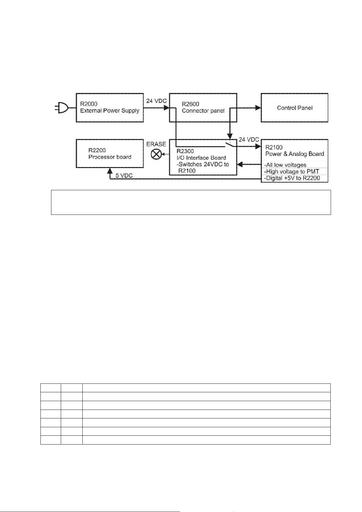
7. Hardware: Electronics
Powering and grounding of the boards:
• Most of the boards are not powered directly = Their power is supplied and/or controlled
by other board(s).
• Order of power supplying:
24VDC from R2000 External Power Supply >> R2600 Connector panel >> R2300 I/O
Interface Board, which switches 24VDC to >> R2100 Power and Analog Board, generates
all low voltages, high voltage to PMT and digital +5V >> R2200 Processor board
• For proper operation all boards must be properly grounded through chassis.
• R2300 I/O-interface board has also interface for control panel
SEE CHAPTER: ”Block diagrams of electronic boards” for further information.
Following is the general description of the electronics boards:
R2000 External Power Supply Unit
• Universal input, auto switching (100-250 VAC / 47-63Hz).
• Output 24VDC 2.3 amps connected to the R2400 connector panel board.
• No serviceable parts inside. Do not open.
R2100 Power & Analog Board
• Analog signal processing circuitry
• Low voltage regulators for all boards & for laser
• High voltage power supply for PMT
• Circuitry for checking the high voltage.
Connectors and indicators on R2100
J101 I/O Generic parallel data I/O to and from R2200 processor board
J102 OUT Laser power to R2300 I/O interface board
J103 IN Measured signal from PMT
J104 IN 24 VDC power from R2300 I/O interface board
J106 OUT HV to PMT (through R2500 high voltage connector board)
J107 OUT 5 VDC power out to R2200 processor board
D2 LED HV active
Digora Optime CLASSIC DXR-50 000 Service Manual 8201053 rev. 5 (2015-09) 20 (87)
Page 21
R2200 Processor Board
• System clock & CPU
• System configuration flash-memory
• Flash not removable, so the corrupted flash can be fixed only at the factory
• General-purpose SDRAM memory
• Ethernet controller & Ethernet interface to R2400 connector panel
• ADC.
Connectors, switches and indicators on R2200
J201 I/O JTAG connector (for board initialization purposes only)
J202 I/O JTAG connector (for board initialization purposes only)
J3 I/O Generic parallel data from R2300 I/O interface board
J205 IN 5 VDC power in from R2100 power & analog board
J203 I/O Generic parallel data from R2100 power & analog board
J204 I/O Ethernet to/from R2400 connector panel board
S3 KEY Firmware reset switch
D4 LED Ethernet operates at 10M speed
D3 LED Ethernet operates in Full duplex -mode
D2 LED Activity
D1 LED Ethernet operates at 100M speed
R2300 I/O Interface Board
• Interface for multiple control, feedback and interface signals from and to R2200 processor board.
• Contains main power switching and multiple input-/output –functions of the scanner.
• Controls erasing lamp on/off and generates a feedback of lamp current to CPU
Connectors and indicators on R2300
J301 I/O 24VDC in from R2400 and 24VDC power on/off to R2100 power &
analog board
J302 I/O R2600 control panel standby –key & -light (through R2400 connector
panel board)
J303 OUT Erasing lamp 24VDC
J304 OUT Plate carrier motor drive
J305 I/O R2600 control panel start –key & 3 indicator lights (through R2400)
J306 IN R2700 laser detector board
J307 IN 5VDC laser power from R2100
J308 OUT Power and control to laser diode in the scanner module
J309 IN Plate carrier home position –optoswitch
J310 IN Safety switch
J311 I/O Plate detect reflective sensor
J312 I/O Mirror scanner assembly drive and feedback
BUZZ1 BEEP The unit audio sub-system
Digora Optime CLASSIC DXR-50 000 Service Manual 8201053 rev. 5 (2015-09) 21 (87)
Page 22
R2400 Connector Panel board
• Passive board for external connectors and internal signal routing.
Connectors on R2400
J402 I/O Ethernet to/from R2200 processor board
J403 I/O R2600 control panel board key and led signals to/from R2300
J404 I/O 24 VDC to R2300 I/O interface board and R2600 control panel signals
to/from R2300
J405 I/O Ethernet RJ45 to hub or network
J406 I/O Ethernet RJ45 to PC
J407 IN 24 VDC from R2000 external PSU
R2500 High Voltage Connector Board
• Connects high voltage from HV-supply to the Photomultiplier tube (=PMT).
J501 OUT HV to PMT
J502 IN HV from R2100 power & analog board
R2600 Control Panel
• Membrane keyboard, which has four led and two keys in it.
• See user’s guide for more detailed description of indicator lights and keys.
• This panel is connected to the R2400 connector panel J403 (signals are routed through
R2400 to the R2300 I/O interface board)
Stand-by key KEY
Power on/stand-by
Start key KEY Readout start
Stand-by light LED If on, R2000 external PSU is properly connected and unit
is switched off. If off, the unit is switched on or PSU is
not properly connected.
RED indicator light LED Error
YELLOW indicator light LED Warning
GREEN indicator light LED Ready, Scanning, Energy save
R2700 Laser detector board
• Contains two pin diodes that are used to synchronize laser movement.
J701 OUT Laser detecting signal to R2300 I/O interface board
Digora Optime CLASSIC DXR-50 000 Service Manual 8201053 rev. 5 (2015-09) 22 (87)
Page 23

8. Field Service Procedures
Service policy:
DIGORA Optime can be sent to Soredex factory for repair if it cannot be repaired by:
• Performing the calibrations and configurations instructed in this manual AND/OR
• Replacing field serviceable parts
Replaceable parts / available spare parts for field service:
Refer to spare parts manual for item numbers
1. R2100 Power & Analog Board
2. R2200 processor board spare part
3a. R2300 I/O interface board DXR-50 to serial numberJ709613 and below.
3b. R2300 I/O interface board DXR-50 from serial number J709614
4. R2400 back panel DXR-50 (Connector Panel Board)
5. R2600 Membrane keyboard (Control Panel)
6a. Reflective Sensor from Optime v.4 = from serial number J709614
6a1. Reflective sensor cable from Optime v.4 = from serial number J709614
6b. Plate Reflective Sensor spare part to Optime v.1- v.3, to serial number J709613 and below.
7. Home Opto Switch w. cable
8a. Erasing Lamp
8b. Erasing lamp socket w. cable
9. Safety Switch DXR-50
10. Microswitch support DXR-50 (Safety switch holder)
11. Top cover Optime
12. Upper cover DXR-50 (Middle cover)
13. Lowest cover DXR-50 (Bottom cover assembly and labels)
14. Intra CR scanner module assy (Optime scanner module assembly spare part)
Mechanical maintenance:
-INTRA CR MECH MAINTENANCE KIT (SP00202)
*GREASE CRC MOS2 KPF 2 K-30 100ML (=lubricant used at SOREDEX production)
*CLEANING & LUBRICATING INSTRUCTIONS
Plate carrier guide rails may need cleaning and lubrication on long term.
Lubricating with improper grease may cause problems!
Test tools for quality control:
- INTRA DIGI QC. STEP PHANTOM W. INSTRUCTIONS (SP00203)
-SDX INTRA DIGI QC IEC PHANTOM W. INSTRUCTIONS (Quality Control IEC PHANTOM)
Both INTRA DIGI QC -phantoms tools come with instructions (SP00204)
Test tools for calibration:
- INTRA SCANNER GEOM CALIBR PHANTOM (Scanner module calibration after replacement)
(SP00205)
Other maintenance:
CONDUCTIVE LUBRICANT CW7100 (201948), may be required for BNC-connector before
serial number J708937
Accessories:
Imaging Plate collector (See ACCESSORY CATALOG)
External Power Supply (See ACCESSORY CATALOG)
Digora Optime CLASSIC DXR-50 000 Service Manual 8201053 rev. 5 (2015-09) 23 (87)
Page 24

Removing the Covers
The correct order of the removal is important when removing all covers:
1. TOP
2. MIDDLE
3. BOTTOM
ALWAYS begin the cover removal by opening the top cover first.
Removing Top Cover
NOTE: if the top lid is removed (or safety switch defective / open / cable disconnected)
>> Unit goes into error state.
You can close the safety switch manually after the erasing lamp has been on shortly
during the startup sequence
>> Unit finalizes the startup-self test without laser sync –error.
IF THE SAFETY SWITCH IS CLOSED BEFORE LAMP FLASHES, PMT MAY DAMAGE!
That is because Optime uses laser and checks the High Voltage during the start-up self-test.
-And laser and high voltage are disabled if the safety switch is open.
• For most small service procedures wait until the unit is initialized before removing the
top cover.
• Most of the service commands will work fine even when the safety switch is open.
• To observe mechanical movement during scan sequence please do following: issue
command <togglehv> while the scanner is in normal mode to disable/enable HV. When
the HV is disabled with <togglehv>, it is ok to make scans top cover open and safety
switch closed. The default mode after power up is naturally HV enabled.
• Light Sensitivity of Photo Multiplier Tube
• The tube is very sensitive to light when it is active. Tube is activated when the
high voltage is turned on and safety switch defeated (=closed). The tube is used
to measure extremely small amounts of light and normal room light and brighter
light sources damage an HV -activated tube.
Top cover is held in place with two “keyhole-locking bars” from the inside.
Top cover cannot be opened just by removing the two screws at the rear side!
TOP COVER REMOVING TO SERIAL NUMBER J811102 (3mm allen key):
• Turn the two screws at the rear counter-clockwise and simultaneously push the screw
inwards. Loosen as long as the screw head starts to rise up.
o Alternative way: loosen both screws 9…10mm (11…12 turns) and then push
inwards as much as they will go
• Lift the top cover off (straight upwards) gently. If the top cover does not come off, loosen
the two screws slightly more, push those inwards and try again.
TOP COVER REMOVING FROM SERIAL NUMBER J811103 (4mm allen key):
• Turn the two screws at the rear counter-clockwise until they stop and lift the top cover off
(straight upwards) gently
Removing Middle Cover
• The top cover and black metallic light cover under top cover must be removed before
removal of the middle cover. The older units have 3mm allen screws while the newer
units have thumb screws.
• Loosen the four screws that fasten the middle cover to the base plate and remove the
middle cover by lifting straight upward.
Digora Optime CLASSIC DXR-50 000 Service Manual 8201053 rev. 5 (2015-09) 24 (87)
Page 25

Removing Bottom Cover
• The top cover must be removed before removal of the bottom cover.
• Remove the two connectors (J402, J404) from the connector panel board R2400.
• Turn the unit so that it stands on its rear face (=the one with type label) and remove the
four screws from the bottom of the scanner.
• Turn the unit right way round to normal position (after removing the bottom screws) and
pull the scanner mechanism out of the bottom cover. Be careful not to damage the
connector panel (R2400) and control panel (R2600) wiring when removing.
Assembling the Covers
The correct order of the assembly is: 1) Bottom >> 2) Middle >> 3) Top
Ensure that covers fit properly to avoid light leaking inside! (Leaking light interferes image
capturing).
Assembling Bottom and Middle Cover
• Insert the scanner mechanism inside the bottom cover (backside first).
• Be careful not to damage the control panel (R2600) wiring attached into the bottom
cover assembly.
• Connect internal connectors (J402, J404) to R2400. Slide the large tubing on top of the
Ethernet connector.
• Remove the plate collector, turn the unit so that it stands on its front face and install the
four screws to the bottom of the scanner. Leave these four a bit (1/2…1 turn) loose
• Turn the unit right way round to normal position (after inserting the bottom screws)
• Install the middle cover with four screws. Leave these four a bit (1/2…1 turn) loose. Skip
this step if you have not removed the middle cover.
• Turn the unit so that it stands on its front face, align bottom cover and tighten the
bottom screws to 1 Nm (100 Ncm) = 12 ft oz.
• Turn the unit right way round.
• Check that the middle and bottom covers align properly
o Gasket sealing from light between bottom and middle cover
o Gasket ends not visible from the outside at rear
o Similar gaps on both sides between bottom and middle cover
o Overall aligned so that has a good visual appearance
• If necessary, loosen the fastening screws and realign.
• Tighten properly all middle and bottom cover screws to 1 Nm (100 Ncm) = 12 ft oz.
Assembling Top Cover
• Before assembling the top cover, make sure that the two keyhole-locking bars are in
correct position (=towards front).
• Ensure that the safety switch closes 1…2mm before the top cover is properly fit.
• Ensure that the top cover fits properly from all edges before tightening the screws.
• Press the cover firmly in place and keep it pressed down while tightening the screws
until you feel resistance. Immediately stop tightening and only continue if pressing the
cover more releases the screwing resistance.
NOTE: Do not use any force when tightening the screws! Just finger-tight them!
Proper tightening torque for top cover screws is 0,25 Nm = 25 Ncm = 3 ft oz.
• If you accidentally tighten the screws with too much force, the covers will probably break
or the top cover becomes very hard to detach later on.
Make sure that the top cover fits properly to the middle cover from all edges!
Digora Optime CLASSIC DXR-50 000 Service Manual 8201053 rev. 5 (2015-09) 25 (87)
Page 26

Calibrations on field service
Follow the <h command> online-instructions; they are updated if calibration routine has
been modified in the future firmwares.
Calibrating (=optimizing) the plate carrier inserting position, <calpr position>
Perform <calpr position> always before reflective sensor calibration
• This ensures that the opening of the plate carrier is properly in front of the sensor when
plate carrier is at plate inserting position.
Calibrating the Reflective Sensor (=plate detector)
• Reflective sensor is used to detect when the protective cover is removed and that the
plate is inserted correctly.
• Readout should start only after detecting the black side of the plate.
• Sensor has to be calibrated if:
o Optime does not start the readout when the plate is correctly inserted
o Optime starts the readout with the cover and plate inserted (cover not
removed)
o Optime starts the readout even without the plate.
o After sensor replacement.
• It is a good preventive action to check the sensor operation (and calibrate, if necessary)
when performing any other service for Optime.
• Use command <plate> to check how detects active / black / none.
• See <h plate> and <h calpr> for instructions. The load value with newer reflective
sensors should be between 3500 – 5000. If values are outside the range please adjust
the home switch flag.
REFLECTIVE SENSOR CALIBRATION BEFORE J709614 (Optime version 01-03)
• Have NO PLATE in plate carrier
• <calpr position> Measures the optimum load position for the plate carrier
(=optimum position for “no plate detection” for <calpr none>)
• <load XXXX> as instructed by <calpr position> / <h calpr position>
XXXX is the "Optimum load offset is XXXX".
NOTE: Parameters can also be negative!
(Example: If output is "Optimum load offset is 1200, command <load 1200>)
• <e> or <ec> Check eject sequence and plate ejecting performance
Adjust with <eject>, if necessary. See <h eject> for instructions.
• <calpr none> When no plate inserted
• <calpr black 80> Sets the detection reference for black to 80
• <calpr active> Have plate + protective cover inserted the right way round.
Let plate be straight (no tilting).
• <calpr active>, as a result you get the value XX for active
• Add 2 to the value XX (Example, if the XX value for active was 20: XX +2 = 22)
• <calpr active XX+2> (Example <calpr active 22>
• <plate> and check the detection result when inserting:
-No plate inserted >> NONE
-Plate in cover >> ACTIVE
*Angle the plate+cover towards left from front edge to see that tolerates
1…2mm tilting before the output turns from “active” to black”.
-Plate wrong way round >> ACTIVE
-Plate right way round >> BLACK
*Angle the plate towards left from front edge to see that tolerates
1…2mm tilting before the output turns from “black” to “none”
Digora Optime CLASSIC DXR-50 000 Service Manual 8201053 rev. 5 (2015-09) 26 (87)
Page 27

REFLECTIVE SENSOR CALIBRATION FROM J709614 (Optime version 04 >>)
• Have NO PLATE in plate carrier
• <calpr position> Measures and sets the optimum load position for the plate carrier
• <calpr all> Follow on-screen instructions
• <plate> Check detection as instructed above
You can use <plate> command in service mode to check correct operation.
Calibrating Resonant Scanner Amplitude
• This may help in case that Optime generates some error related to the scanner module
(Laser synchronization, Degraded image quality -message, Error # 34 & 35 etc…)
• Refer to Technical Info TI-1086 for more details
• Necessary after R2300 IO interface board replacement
• Warm up the unit to the room temperature
o Do not ignore the warm up procedure in previous step – scanner amplitude is
naturally larger when cold with the same driver voltage than in the normal
operation temperature
• Calibrate resonant scanner amplitude by <calga> (safety switch must be closed)
• If <calga> is not completed successfully, check that:
o Laser turns on
o Mirror scanner oscillates (=makes the laser line)
o Connectors from R2300 I/O-board to the scanner module are OK.
• Note! Verify image geometry after performing <calga>
(calga changes the amplitude setting <ga> for resonant scanner amplitude).
Digora Optime CLASSIC DXR-50 000 Service Manual 8201053 rev. 5 (2015-09) 27 (87)
Page 28

Gear ratio calibration, from Firmware ver. 0.57. Command <gear>
-If the belt tightness is adjusted or changes by itself during usage, that changes also the
reduction gear ratio of Optime plate carrier drive.
-Incorrect gear ratio causes error to horizontal (=slow scanning) dimension of images.
-Correct gear ratio has to be set by calibrating <gear> -parameter as instructed below.
-When <gear> is calibrated correctly, the image measurements will be exact. In addition this
improves the precision and functionality of automatic plate size detection (= prevents for
example size 2 ip to be shown in size 3 window of DfW)
-If the belt tightness has been changed or adjusted, you have to upgrade firmware 0.57 and
perform <gear> parameter setting
-You need to take an X-ray image with some kind of phantom (image must not be uniform gray)
to be able to perform <gear> setting
-Instructions for <gear> -parameter setting can be found with command <h gear> from service
mode
<gear> ratio calibration instructions:
Syntax: <gear [ratio]>. Sets the reduction gear ratio for plate carrier movement
• Must be set directly after the belt tension has been adjusted.
• Greater difference from the default almost certainly means that the belt is slipping or the
measurement for gear is made incorrectly.
• For the units before serial number J1118616 the nominal gear value is 54500. For the
units starting from serial number J1118616 the nominal gear value is 48000.
Follow the procedure below to adjust the gear parameter:
1. Check that super resolution is selected / set the resolution to super as follows:
• Options >> Digora Optime scanner Setup >> Image Scanning
Resolution: Super
It is IMPORTANT to have SUPER resolution selected!
(HIGH -resolution setting results incorrect measurement values)
2. Start the adjustment with the value of 57000 for the gear (command <gear 57000>)
3. Measure the length of the size 2 IP to be used (X0, measured imaging plate, nominal
41mm) with accuracy of 0.1mm.
4. Exposure size 2 imaging plate fully using some phantom.
It is IMPORTANT not to take an empty exposure (USE SOME KIND OF PHANTOM)!
5. Read the image normally
6. Be sure that the image is calibrated for 25lp/mm as follows:
• Open image with DfW
• >> Calibration >> Image Resolution >> Calibrate >> Advanced
Horizontal (pixels / mm) Set to 25
Vertical (pixels / mm) Set to 25 >> End
7. Scan and measure the width of the exposed area from the image exactly from edge to
edge with the measurement tool of application. Result = X1
• Measure only the exposed area (=leave the white area outside measurement)
• Measure X1 as precisely as possible.
• Use all digits of X1 for the following calculation
Note: If start of the image is not visible decrease start parameter.
8. Set the new gear value to:
X1 (measured from image with DfW) / X0 (measured from the imaging plate) x 57000.
9. Read another exposed ip and measure the width of the image as described in 7.
Adjust <start> parameter (see instructions below).
10. Set the resolution back to high, if you wish
Example values for one Optime´s <gear> calibration:
-Measured the exposed area of the image at DfW (X1): 36,88 mm
-Measured the width of the imaging plate (X0): 41,0 mm
(36,88 [divided by] 41,0) x 57000 = 51272
Digora Optime CLASSIC DXR-50 000 Service Manual 8201053 rev. 5 (2015-09) 28 (87)
Page 29

Adjusting the Plate Carrier ( <eject>, <load> and <start> ).
Plate carrier parameters are used to control the plate handling positions.
Adjust these parameters only in case that there is some problem with plate insertion /ejection, image centering or plate detection and/or reflective sensor calibration.
If adjusted, order is: 1) <calpr position> / 2) <eject> / 3) <start>
LOAD (LOAD AND PLATE DETECTION POSITION):
Sets the optimum plate carrier position for plate insertion and plate detection (opening in the
plate carrier is optimally in front of the reflective sensor)
Plate carrier position for plate insertion and plate detection, command <load XXXX>
• Optimized by performing <calpr position> as instructed in this manual
EJECT:
The main idea of <eject> -parameter adjustment is to set the parameter so that the ejecting
mechanism is fully utilized
Eject force, command <eject XXXX>
• Bigger value for <eject XXXX> =Longer eject movement (= ”Stronger eject”)
• Smaller value for <eject XXXX> =Shorter eject movement (= ”Weaker eject”)
• Plate carrier must not hit the front end at the end of eject movement
START (IMAGE HORIZONTAL POSITION):
Sets the plate carrier position in which the laser is turned on (=start of image readout)
Coarse check/ adjustment for image position horizontally left-right (top cover removed):
1. <laser 1> + have safety switch closed
2. <e>
3. Check that the laser points to the start of the plate at the moment when stops shortly in
front of the plate collector (see illustration below)
Fine tuning the image position horizontally (LEFT - RIGHT), command <start XXXX>
• Expose and read image, check horizontal position from the image
• Adjust with <start XXXX)
BIGGER value for <start XXXX> Moves the IMAGE LEFT in application window
SMALLER value for <start XXXX> Moves the IMAGE RIGHT in application window
NOTES:
• Parameters can also be negative.
• You can always restore the original factory setting which is shown in (parenthesis).
• You can restore all factory set parameters with command <restore configuration>.
Digora Optime CLASSIC DXR-50 000 Service Manual 8201053 rev. 5 (2015-09) 29 (87)
Page 30

Eject adjustment to serial number 709613 (v. 1-3, original reflective sensor, <refltype 0>):
1. <eject 9000> while in service mode
2. Insert size 0 plate (if available, it is the most critical size for eject performance)
3. Command <e> or <ec> and observe the plate eject performance
4. <eject 9500>, observe plate ejecting
5. Increase the value XXXX of <eject XXXX> by increments of 500, command <e> or >ec>
until the plate ejects
6. Add 1500 to the value with which the plate was ejected and command <eject YYYY>
YYYY = value XXXX when the plate was ejected + 1500
(Example: If the plate was ejected with 11500, command <eject 13000>)
7. Command <e> or <ec> and observe the plate eject performance with all plate sizes
Eject adjustment from serial number 709614 (v. 4 >>, new reflective sensor, <refltype 1>):
1. <eject 13000> while in service mode
2. <calpr position>
3. Check that the plate carrier is 0,5…2mm out from the unit door
4. Insert size 0 plate (if available, it is the most critical size for eject performance)
5. Command <e> or <ec> and observe the plate eject performance
6. <eject 13500>, observe plate ejecting
7. Increase the value XXXX of <eject XXXX> by increments of 500, command <e> or >ec>
until the plate ejects
8. Add 1500 to the value with which the plate was ejected and command <eject YYYY>
YYYY = value XXXX when the plate was ejected + 1500
(Example: If the plate was ejected with 14000, command <eject 15500>)
9. Command <e> or <ec> and observe the plate eject performance with all plate sizes
Centering the image vertically, FINE TUNING (UP – DOWN)
• Fine tuning for image vertical centering can be done by changing parameter <ds>
• Maximum allowed change for <ds> -value is +/-300 from the factory-set value.
• DECREASING <ds XX> Moves the IMAGE UP in DfW -window
• INCREASING <ds XX> Moves the IMAGE DOWN in DfW -window
Centering the image vertically, COARSE ADJUSTMENT from serial nr. J501607
• If the image cannot be vertically centered by changing <ds XX> as instructed above, it
may be necessary to adjust the plate carrier mechanically up or down as follows.
• Valid from the units manufactured from May 04th 2005, serial nr J501607:
Vertical position adjustment of the plate carrier:
1. Loosen two small screws and one bigger at the middle on top of the plate carrier
2. Adjust equally with two screws on top (tightening moves the plate carrier down)
3. Tighten the bigger middle screw on top
4. Tighten the two smaller screws on the top
• Moving PLATE CARRIER UP Moves the IMAGE UP in DfW -window
• Moving PLATE CARRIER DOWN Moves the IMAGE DOWN in DfW -window
Digora Optime CLASSIC DXR-50 000 Service Manual 8201053 rev. 5 (2015-09) 30 (87)
Page 31

Configuration parameters
Showing / setting configuration parameters (FS = factory setting)
• <CONF> shows some special configuration parameters <refltype> etc
• <conf> shows all configuration parameters of Optime
-factory settings are shown in parenthesis, like (60)
• <parameter> Shows the active and factory setting of parameter
• <parameter XX> Sets parameter value to XX, factory setting remains.
Autostart <autoscan> (FS 400, starts automatically 0,4sec after cover removal)
• <autoscan 0> Configures Optime to start readout after START pressed
• <autoscan 600> Configures Optime to start readout AUTOMATICALLY 0,6 seconds
after plate cover is removed
(<autoscan XXX>, XXX =delay in milliseconds)
RECOMMENDED 200…400, MAX. 600
Beeper (FS 1 = all beeps enabled)
• <beeper 0> disables extra beeps (when going to idle mode etc…), but leaves all
error and warning beeps enabled
• <beeper 1> Enables all beeps (including when going to standby mode etc…)
Standby mode <idle> (FS 600 seconds = unit waits 10 min before entering standby)
• <idle> Shows time (seconds) Optime waits before goes to energy-save (60)
• <idle XXX> Sets time (XXX seconds) Optime waits before goes to energy-save
Automatic shutdown <off> (FS 240 minutes = unit shuts down after 4hrs)
• <off> Shows time before automatic shutdown (minutes, 240 DEFAULT)
• <off XXX> Sets time (XXX minutes) before automatic shut-down
Restoring factory settings
• <restore configuration> restores the factory settings for all <conf> -parameters
-Works only from Optime firmware 0.42.
• You can also restore individually each parameter to their factory settings by
commanding <parameter XXX>, (XXX = factory set value in parenthesis after set value)
Digora Optime CLASSIC DXR-50 000 Service Manual 8201053 rev. 5 (2015-09) 31 (87)
Page 32

Firmware (=FW) and core upgrading
Firmware and core upgrading is done using s2terminal –program
(CAN NOT be done with Service Assistant –utility of the application!).
• You do not have systematically to upgrade newest version of firmware and core to all
Optime units, unless SOREDEX technical support has instructed so.
But it is recommended to upgrade latest FW and core in case you do any other service.
• SOREDEX strongly recommends to update also the latest FW and core at the
same time.
• Using the latest FW and core versions provides the unit with all features and
improvements
• WHEN UPGRADING BOTH FW AND CORE TO THE NEWEST VERSIONS AT THE
SAME TIME, THEY WILL BE BACKWARDS COMPATIBLE TO OLD UNITS
o Firmware version 0.57 is needed to be able to perform <gear> -calibration.
Upgrading requires the following files to be copied to same folder (
DIGORATM Optime Classic (DXR-50 000) FW and core upgrading:
• Uid.srec Firmware file
• UIDcoreXX.pof Core file, version XX
• s2terminal.exe Needed to run s2terminal (Must be version dated 22/05/2009 or later)
• s2.dll Needed to run s2terminal (Must be version dated 21/05/2009 or later)
•
W32N55.dll Needed to run s2terminal (Must be version dated 09/04/2008 or later)
•
W32N55.ini Needed to run s2terminal (Must be version dated 09/04/2008 or later)
(S2Terminal has to be version 3.2.127.0 or later, shown when S2terminal runs)
NOTE: It is OK to have all above mentioned FW and core files for both the
Classic and the new Optime and display graphics file for new Optime in the
same folder.
S2terminal can recognize which version of Optime is connected, and will download
the correct file(s) to it.
Following page has the instructions for FW and core upgrading
for example C:\s2terminal):
Digora Optime CLASSIC DXR-50 000 Service Manual 8201053 rev. 5 (2015-09) 32 (87)
Page 33

Firmware (=FW) upgrade
Following commands are needed to upgrade FW.
o Type <xh> in the command prompt to see the instructions for the command syntax.
o Command <xs> Starts the firmware upgrade and restarts the scanner unit after
upgrade is finished
o After restart type <h> check the FW version
o Switch scanner unit off and on to see that there are no errors during start up.
1. Copy the new firmware file (to be downloaded to the unit) to the same, dedicated folder (for
example c:\s2terminal) with the s2terminal files = from which you will start the s2terminal.
2. CHECK THAT DfW (or other imaging application SW) IS CLOSED!
(Type <xh> in the command prompt to see the instructions for the command syntax.)
3. Command <xs> Starts the firmware upgrade
If the upgrading was successful, you should have the output similar to follows:
xs
Transferring program (or transferring firmware)
Firmware data sent, waiting for flashing...........
Resetting...
Login fail (no connection).
Login fail (no connection). It is normal that this “Login fail…” –message appears several times
Connected to Optime
Software (Firmware) version X.XX
Core version XX
Serial number XXXXXXX
Etc…
ending with Optime vX.XX> (vX.XX should now equal to the new firmware version)
Core upgrade
• You do not have systematically to upgrade newest core to all scanner units, unless technical
service has instructed so, but it might be good thing to do in case you do any other service
for scanner unit
• Firmware upgrading is done using s2terminal -program (cannot be done with Service
Assistant on the Application software!).
1. Copy the core file to the same, dedicated folder with s2terminal files
(for example C:\s2terminal).
2. CHECK THAT Application SW IS CLOSED!
3. Execute the s2terminal program using the unit’s IP –address
4. Command <xc XX> or <xc XXX> (XX or XXX = version number in the core filename)
>> Starts the core upgrade
5. Wait until s2terminal tells that upgrade is finished
6. Switch scanner unit off
Digora Optime CLASSIC DXR-50 000 Service Manual 8201053 rev. 5 (2015-09) 33 (87)
Page 34

Replacing External Power Supply
• Just plug in the new external power supply. No adjustments or calibrations required
Replacing R2100 Power & Analog Board
• Open the electronics box lid and replace R2100 with new board
NOTE: BNC-connector located on the solder side of R2100
• No calibrations or configurations required after replacement
TIP: You can access R2100 and R2200 as follows:
-Remove the top cover
-Turn Optime upside down
-Remove the four screws fastening the bottom cover
-Gently pull out the bottom cover and disconnect the two connectors from R2400 before
completely removing the bottom cover.
-Remove the electronics box lid.
Replacing R2200 Processor Board
All factory calibrations and parameter settings are stored in the flash of R2200.
These settings must be stored from the original R2200 and configured to the new board.
If you just replace the board without setting the configuration parameters, the unit will not work.
REFER TO THE INSTRUCTIONS PROVIDED WITH SPARE PART R2200
• Open service assistant from DfW (or enter service mode from s2terminal)
• Command <s>
• Command <conf>
• Copy all configuration parameters and paste to Notepad, Word etc.
• Save these settings with a filename JXXXXXX_conf, for example.
(Alternatively record all parameters manually)
• Open the electronix box lid and replace R2200 with new board
• Connect all connectors to R2200 and fasten the electronics box lid
• Insert the scanner mechanism to the bottom cover (connect R2400 connectors)
• Connect power and Ethernet -connectors
• Switch Optime on
• Start command prompt of windows, make connection and upgrade latest firmware (and
core) version(s) as described in this manual
• Command <s>
• Configure all parameters as they were on the original board (except calpr active / black /
none)
• Configure the reflective sensor type:
o <refltype 0> For units before serial number J709614, with original plate sensor type
o <refltype 1> For units from serial number J709614, with new plate sensor type
• Calibrate reflective sensor as instructed in this manual
• Configure serial number to the new board, command <serno J XXXXXX>
• If R2200 does not boot at all and you do not have the original configuration values
available, you must get the original factory set configuration data from Soredex technical
support (please notice that the values received from technical support are factory
calibrated values. Gear, start and load value might be changed if belts are tightened.
Geometric calibration is recommended to run after CPU replacement.) Please follow
instructions from appendix 1
Replacing R2300 I/O Interface Board
• Perform <calga> after replacement. Refer to chapter “calibrations” on how to do this.
Digora Optime CLASSIC DXR-50 000 Service Manual 8201053 rev. 5 (2015-09) 34 (87)
Page 35

Replacing R2400 Connector Panel Board
1. Remove all covers
2. Disconnect the internal connectors from R2400
3. Remove the two screws fastening R2400 to the bottom cover
4. Check that the power and Ethernet -connectors are fitting properly in their openings
when installing the new R2400 Connector panel board.
Replacing R2600 Control Panel
Control panel is available individually or as attached to the bottom cover.
Refer to spare parts manual for available options
Remove the defective R2600 control panel and install the new one as the original was:
1. Disconnect J403 from R2400
2. Remove the old control panel and adhesive tapes
3. Install the new control panel (bend the cable as the old one was =straight)
4. Attach double-sided adhesive to the flat cable (note the correct side)
5. Fasten the flat cable to the left wall of the middle cover (Have most of the extra length at
front side)
6. Fasten the 250mm long adhesive tape on top of the flat cable
7. Connect flat cable to R2400, pin 1 towards right (Pin 1 marked with square pad)
Replacing Reflective Sensor
Units from serial number J709614 have a different, improved type of reflective sensor,
which does not fit to the older units. Also R2300 I/O board is different version from
J709614.
Units to serial number J709613 have the original type of reflective sensor and R2300 I/O
board.
Spare part sensor up to J709613 will have a double-sided adhesive included. This adhesive is
required only if installing sensor to a Optime serial number J502925 and below, since they have
different location for the fastening screw.
Refer to TI1067 & spare parts manual for available options and compatibility information.
1. Remove all covers.
2. Remove the front panel by opening the three screws fastening the panel to the base
plate.
3. Remove the old sensor
4. Fasten the new sensor using the double-sided adhesive so that the sensor front head is
flush with the support structure.
5. Fasten sensor cable to the front plate with cable ties
6. After replacing the sensor, reconfigure the required parameters ( <calpr position> /
<load> <calpr>) as instructed in the calibration chapter.
Replacing Home Opto Switch
1. Remove the top cover
2. Remove the Light Protection cover by opening the two screws on top of it.
3. After replacing the opto switch, check the plate insert / readout start / ejecting performance.
Refer to chapter “Adjusting plate carrier”
Replacing Erasing Lamp
1. Remove the top cover
2. Remove the Light Protection cover by opening the two screws on top of it.
3. Remove the old erasing lamp by pulling it straight upwards.
NOTE: Do not touch the new lamp with bare fingers when installing it!
4. Push the new lamp firmly into its socket.
Digora Optime CLASSIC DXR-50 000 Service Manual 8201053 rev. 5 (2015-09) 35 (87)
Page 36

5. Test the lamp operation from service terminal: <erase 1> <erase 0>.
Replacing Safety Switch
• Ensure that the newly replaced safety switch closes 1…2mm before the top cover is
properly fit to the middle cover.
• When the switch is closed, output must be 1 after commanding <cover>
Replacing Safety Switch holder
• Units from serial number J503179 have a safety switch holder which moves the switch
5mm towards right (towards the plate carrier mechanism).
• This is to ensure that the switch remains closed when top cover is installed
• Adjust so that the holder is straight (in 90° angle to the scanner module) and that top of
the holder is 13,5mm (+/- 0,5mm) from the scanner module top surface
Replacing covers
• See instructions of cover removal and re-installation in this manual
NOTE: Bottom cover has the type label attached. If the Bottom cover needs to be replaced, you
have to take the type label from the original cover.
Replacing scanner module
• Refer to instructions provided with the spare part –scanner module
NOTES ON SCANNER MODULE REPLACEMENT
REPLACING SCANNER MODULE NEEDS EXTREMELY PROPER CALIBRATION
PROCEDURE!
• GEOMETRY CALIBRATION PHANTOM REQUIRED
• PROPER SERVICE TRAINING REQUIRED
REFER TO THE INCLUDED INSTRUCTIONS
or
CONSULT SOREDEX TECHSUPP FOR ASSISTANCE
SPARE PART SCANNER MODULE DOES NOT INCLUDE THE SAFETY SWITCH.
TAKE THE SAFETY SWITCH FROM THE ORIGINAL SCANNER MODULE.
SCANNER MODULE CONTAINS NO FIELD SERVICEABLE PARTS,
CAN BE REPLACED ONLY AS A WHOLE ASSEMBLY!
ASK FOR AVAILABILITY OF REFURBISHED SCANNER MODULE
Digora Optime CLASSIC DXR-50 000 Service Manual 8201053 rev. 5 (2015-09) 36 (87)
Page 37

Drive Belt (grey/black): Cleaning, tension check, adjustment and replacement
CLEANING:
• Clean the drive wheel, motor shaft and inner surface of the belt with using lint free tissue
dampened with rubbing alcohol (ethanol) and wipe clean
TENSION CHECK:
• Suitable tension of the belt = as little friction as possible while sustaining the movement.
• Rotate big drive wheel manually slowly >> the motor drive shaft rotates along with it.
• Rotate the motor shaft from the brass or rubber flywheel so that the eject-mechanism
starts to utilize. The belt must not slip during the eject movement spring is compressed
(=most resistance for the carrier movement)
• Command <ec> + press start and observe the movement of the plate carrier
ADJUSTMENT:
1. Loosen the four motor fastening screws ½ to 1 turn equally.
2. Adjust the belt tension with adjustment screw. Start adjustment with very low tension.
3. Rotate the big drive wheel and increase tension gradually until the motor shaft rotates
along with it.
4. issue the <ec> command from the service terminal + press start. Plate carrier movement
must not stop when the motor speed/current is changed to lower setting (this happens at
the moment when the inwards movement of the carrier is slowed down). Observe that
the plate carrier moves all the way (including the whole ejecting mechanism movement)
and does not (but perhaps barely) slip any more.
5. Tighten adjusting screw one additional full round
6. Tighten the four motor fastening screws
7. Loosen the adjustment screw 1/4 round
8. Command <ec> + press start and observe the movement of the plate carrier
9.
Perform < gear > calibration as instructed in this manual
REPLACEMENT:
Refer to drawing below and perform above mentioned adjustment procedure
REPLACEMENT 1:
Remove the shaft
locking washer
Adjust to the limit that the motor shaft follows when rotating
big drive wheel manually / when commanding <ec>:
>> Belt does not slip during eject movement
ADJUSTMENT 2:
-Then tighten the screw one full turn more.
REPLACEMENT 2:
Move the drive wheel
and replace the belt
ADJUSTMENT 1:
Loosen a bit the 4 screws
holding the motor before
adjusting the belt tension.
Digora Optime CLASSIC DXR-50 000 Service Manual 8201053 rev. 5 (2015-09) 37 (87)
Page 38

Plate carrier belt (conveyor belt): Tension check and adjustment
Plate carrier tension check:
• Rotate the motor shaft from the flywheel or from drive wheel so that the eject-
mechanism starts to utilize. The plate carrier belt (conveyor belt) must not slip during the
eject movement (=most resistance for the carrier movement)
• Command <ec> + press start and observe the movement of the plate carrier
• Suitable tension of the belt is checked with the special tool SP00555(refer for the spare
part catalog for detailed item information)
Adapter knob must be up as in the image.
Rise and rotate counterclockwise to get it to correct position if
wrong.
• Move plate carrier as far back as it goes by manually rotating the drive wheel
• Insert the tool in the middle of the belt. Ends of the tool against the end pieces of the
plate carrier rail mechanism
Check / adjust between top and bottom lines.
(Optimal at middle line
= two rings shown).
Digora Optime CLASSIC DXR-50 000 Service Manual 8201053 rev. 5 (2015-09) 38 (87)
Page 39

B
Belt tension adjustment:
• Loosen the locking screw (A) (allen hex 2,5mm tool) at the front face of the plate carrier.
Leave locking screw just a bit tight (so that the adjustment screw (B) can be turned but
does not slip back by itself)
A
•
Rotate adjustment screw (B) with flat screwdriver so that two rings is visible in the tool
This is optimal position. See following images.
MAXIMUM LIMIT
Three rings shown
• Hold the adjustment screw in its position with flat screwdriver
• Tighten the locking screw (A)
• Check the tightness. Re-adjust if necessary.
OPTIMAL
Two rings shown
.
MINIMUM LIMIT
One ring shown
Digora Optime CLASSIC DXR-50 000 Service Manual 8201053 rev. 5 (2015-09) 39 (87)
Page 40

Plate carrier drive mechanism: cleaning and lubricating
Clean drive belt , motor shaft and drive wheel + conveyor belt and it´s drive wheels
Clean the guide rails and the plate carrier parts against them
For cleaning, use lint-free cloth dampened with rubbing alcohol (ethanol).
• Remove drive belt from the drive wheel and motor shaft (just push the belt off the drive
wheel)
• Clean the inside surface of the plate carrier belt. Clean also the drive shaft of the plate
carrier belt. Rotate from drive wheel back and worth to ease the cleaning.
• Clean the motor shaft
• Clean the drive wheel and drive belt
• Re-install the drive belt
o See chapter “Drive Belt: Cleaning, tension check, adjustment and replacement”
in this manual.
Lubricate the plate carrier guide rails and the plate carrier parts against them, as
For lubricating, use ONLY GREASE CRC MOS2 KPF 2 K-30
Lubricating with improper grease may cause movement problems!
NOTE:
INTRA SCANNER MECH MAINTENANCE KIT includes (SP00202):
Lubricant for Optime guide rails (GREASE CRC MOS2 KPF 2 K-30)
= Same lubricant that is used at SOREDEX production
+ cleaning and lubricating instructions
Digora Optime CLASSIC DXR-50 000 Service Manual 8201053 rev. 5 (2015-09) 40 (87)
Page 41

Maintenance
Annual maintenance is not mandatory. However, it is recommended to check the following
topics during site visit or other service activities:
ROUTINE CHECKS WITHOUT OPENING THE UNIT:
• Scan a test image using SDX INTRA DIGI QC IEC PHANTOM W (SP00204)
INSTRUCTIONS (SOREDEX IEC Quality Control phantom), and check the image
quality
o Refer to the instructions provided with the test tool for image quality criteria
• Check image geometry (measure the length and and re calibrate <gear> if necessary)
• Check that reads and shows all 4 IP sizes properly
• Check all Imaging plates by exposing without a phantom
o No scratches, spots etc.?
o Need of cleaning?
o Need for replacing?
ROUTINE CHECKS WHEN UNIT OPENED:
• Light Sensitivity of Photo Multiplier Tube
• The tube is very sensitive to light when it is active. Tube is activated when the
high voltage is turned on and safety switch defeated (=closed). The tube is used
to measure extremely small amounts of light and normal room light and brighter
light sources damage an HV -activated tube.
• Check the belt tension:
o Rotate drive wheel manually slowly >> the motor drive shaft rotates along with
o Rotate the motor shaft from the brass (or rubber) flywheel so that the eject-
mechanism starts to utilize. The belt must not slip during the eject movement
(=most resistance for the carrier movement when the eject spring is pressed)
o Command <ec> + press start and observe the movement of the plate carrier
o See chapter “Drive Belt: Cleaning, tension check, adjustment and replacement”
in this manual.
• Clean drive belt , motor shaft and drive wheel + conveyor belt and it:s drive wheels
o Use lint-free cloth dampened with rubbing alcohol (ethanol)
o See instructions “Plate carrier Belt (conveyor belt): Tension check and
adjustment” in this manual.
• Tighten the drive belt if got too loose (=the plate carrier not moving properly).
o See instructions “Drive Belt: Tension check, adjust and replacement” in this
manual.
• Tighten the plate carrier (conveyor) belt if gets too loose (=the plate carrier not moving
properly).
o See instructions “Plate carrier Belt (conveyor belt): Tension check and
adjustment” in this manual
• Clean and Lubricate the plate carrier rails if dusty / dirty or lacking lubrication
o Use lint-free cloth dampened with rubbing alcohol (ethanol) for cleaning
o Use “Lithium MoS2” -grease (CRC “SUPER LONGTERM GREASE + MOS2”, or
equivalent). Apply thinly and move manually back and forth.
Digora Optime CLASSIC DXR-50 000 Service Manual 8201053 rev. 5 (2015-09) 41 (87)
Page 42

NOTE: Using improper lubrication may cause problems!
• Check the movement of the eject mechanism
o Use silicone or teflon based, fine lubrication if required
• Check that the ejecting mechanism is not making noise when moving.
o Lubricate the spring rod with or teflon based, fine lubrication if required
• Check that the plate carrier is not hitting the plate guide (=aluminium block beside the
erasing lamp reflector)
o Between plate carrier and plate guide there must be gap which is less than the
thickness of the imaging plate
o Adjust the plate guide by loosening the two fastening screws from top, if
necessary
• Check that the plate carrier is not hitting the light collector cylinder (reflecting aluminium)
o Must be about 0,5mm clearance in between
• Check the bearings and shaft fastenings
o Check that the brass or rubber flywheel on the motor shaft is not touching the
frame or the belt
o Check that the plate carrier belt drive pulley (close to front plate) is properly
fastened with set screw
Optime with hinged door, to serial number J501606:
• Lubricate the two lower scanner door “notches” which make the plate carrier to activate
the door to open (with some clear lubricant: silicone, teflon etc.)
Optime with sliding door, from serial number J501607:
• Check the sliding movement of door and movability of all mechanism joints
o Use silicone or teflon based, fine lubrication if necessary
Digora Optime CLASSIC DXR-50 000 Service Manual 8201053 rev. 5 (2015-09) 42 (87)
Page 43

9. Diagnostics / Self diagnostics
ADC-input reading -test <debug 9> activated from service terminal
This test is very useful when troubleshooting certain hardware (image signal) problems
• Have all covers installed
• Command <debug 9> from service mode
• Optime drives the plate carrier in, activates high voltage and starts to measure the ADC-
input signal. Output value on the screen should be as follows:
o Should be 0 when scanner door is closed. If much above 0 when door closed:
Light leakage?
PMT?
Power and analog board?
o Should increase when you open the scanner door manually. If stays close to 0:
PMT?
Power and analog board?
• Test is stopped pressing shutdown button.
Automatic Self –Diagnostics on power-up
The scanner automatically carries out self-diagnostics each time it is powered up.
The initialisation sequence is described here.
1. Flash all indicators
2. Calculate the CRC (if enabled)
3. Start blinking the yellow led
4. Drive the plate carrier home (to reset the location counter)
5. Drive the plate carrier back inside
6. Calibrate PMT-signal amplifier
7. Test high voltage (if safety switch is closed)
8. Test erasing lamp
NOTE: When the top cover is off (= safety switch open), Optime will generate an error
(=red light on) during start-up. You can close the safety switch manually after the erasing
lamp has been on shortly >> Optime finalizes the startup-selftest without error.
9. Optionally perform a warm-up sequence
10. Wait the mirror scanner stabilizing (uses laser; close the safety switch to proceed if the
cover is open)
11. Drive the plate carrier to loading position
12. Stop flashing the yellow led and turn on the green led, if everything is ok
13. If there is no client connected, the yellow indicator remains on
14. If the Ethernet cable is not properly connected, the yellow indicator flashes
Self-diagnose test activated from service terminal
• More throughout diagnostics can be performed from service terminal in service mode
• This differs from the power-up diagnostics in the way that it requires user interaction and
diagnostic coverage is somewhat larger
• Commanding <h diagnose> shows the help.
• Insert plate into the plate carrier before starting <diagnose> -test, otherwise the
reflective sensor test may fail.
NOTE: Optime asks you to press the control panel keys during self-diagnose. If
not pressed, generates a timeout.
Digora Optime CLASSIC DXR-50 000 Service Manual 8201053 rev. 5 (2015-09) 43 (87)
Page 44

Self-test (=Endurance Test) activated from service terminal
• You can use Optime´s “endurance test” for troubleshooting and for monitoring operation
• ENDURANCE TEST CAN NOT BE OPERATED IN SERVICE MODE
• <test XXXX YYY> performs endurance test YYY times with pause of XXXX milliseconds
o Endurance test = runs the normal readout/erase -cycle
o Example: <test 5000 100> makes 100 tests with 5 seconds pause
o Have top cover on OR command <togglehv> + keep the safety switch closed
when issuing <test XXXX YYY)
• NOTE: Disconnect Ethernet cable or close DfW if you have started the endurance test
from the Service Assistant(=to avoid blank images appearing on the open patient card)
• Later on it can be checked from the service log of the unit (<log>, see chapter Service
Log), if there were any errors during this test.
• Light Sensitivity of Photo Multiplier Tube
• The tube is very sensitive to light when it is active. Tube is activated when the
high voltage is turned on and safety switch defeated (=closed). The tube is used
to measure extremely small amounts of light and normal room light and brighter
light sources damage an HV -activated tube.
Digora Optime CLASSIC DXR-50 000 Service Manual 8201053 rev. 5 (2015-09) 44 (87)
Page 45

10. Block diagrams of electronic boards
Digora Optime CLASSIC DXR-50 000 Service Manual 8201053 rev. 5 (2015-09) 45 (87)
Page 46

Digora Optime CLASSIC DXR-50 000 Service Manual 8201053 rev. 5 (2015-09) 46 (87)
Page 47

11. Warnings and precautions
Operating Warnings and Precautions
CLASS 1 LASER EQUIPMENT
DANGER: Any failure to follow the recommendations and instructions in this
manual may expose the user to laser radiation exceeding the class 1 specifications.
CAUTION:
• Do not move or knock the scanner when it is scanning.
• The use of control or adjustment or performance of procedures other than those
specified herein may result in hazardous laser radiation exposure.
• This scanner must only be used to read SOREDEX image plates and must not be used
for any other purpose. Only use the imaging plates and protective covers that are
supplied by SOREDEX with the PCT scanner. NEVER use imaging plates or protective
covers from other manufacturers with the scanner
• This scanner, or its accessories, must not be modified, altered or remanufactured in any
way.
• Only the manufacturer’s authorized service personnel are authorized to carry out annual
maintenance and repair. There are no user serviceable parts inside.
• This device can interfere with other devices due to its EMC characteristics.
• Other devices can interfere with this device due to their EMC characteristics.
• This device complies with IEC 60601-1 standard. Accessory equipment connected to
this device must be in compliance with the related nationally harmonized IEC standards.
• Equipment not suitable for use in the presence of flammable anesthetic mixture with air
or with oxygen or nitrous oxide.
• Only use the power supply unit that is supplied with the scanner. Do not use any other
power supply units with the scanner.
Servicing Precautions
Laser Radiation
There is a class 3B laser inside the scanner. The laser can be activated if the safety switch is
defeated and the laser is switched on from the service terminal. Avoid direct exposure to the
beam or its’ reflections (for instance from shiny tools etc).
High Voltage
There is a high voltage circuit between the photo multiplier tube and amplifier card. High voltage
can be set on when the safety switch is defeated.
Light Sensitivity of Photo Multiplier Tube
The tube is very sensitive to light when it is active. Tube is
activated when the high voltage is turned on and safety switch
defeated (=closed). The tube is used to measure extremely small
amounts of light and normal room light and brighter light sources
damage an HV -activated tube.
Digora Optime CLASSIC DXR-50 000 Service Manual 8201053 rev. 5 (2015-09) 47 (87)
Page 48

TROUBLESHOOTING DIGORA Optime DXR-50 000
Troubleshooting by using Error codes
• Present error code is shown in application SW and in s2 terminal (service software).
• Error codes are also stored in the service log inside the unit. Service log can be read by
using S2 terminal or Service assistant (for more info, see chapter service log).
• Correct service instructions can be found from the list below by using error code number
as a reference.
LIST OF ERROR CODES
Error 032 Carrier home too early (maybe stuck during the eject
movement)
Cause
- The plate carrier is not moving properly. This is recognized when the home optoswitch
activates too early.
- The plate carrier is hitting the plate guide (aluminium piece inside the scanner)
- The plate carrier is hitting the light collector
- Eject mechanism is jamming the plate carrier movement
- Belt(s) slipping
- Home opto-switch is broken.
Check
- Movement of the plate ejecting system <e> <ec>
- Movement of the plate carrier, the gear belts and belt wheels
- Belt tightness check and cleaning
- Adjustment of the plate guide and light collector (must be about 1mm gap).
- Operation of the home optic switch <home>
Solutions
- Adjust the plate guide by loosening the two fastening screws from top and re-tighten
- Adjust / bend slightly the light collector cylinder
- Clean the belts and drive wheels & shafts (and tighten the belt, if necessary), as instructed in
service manual
- Clean and lubricate the gliding parts, as instructed in service manual
- Check/re-solder R2200 flat cable connectors (if SMD-type) or replace R2200 with version R4.
- Replace R2100 with rev. 3 or newer
Digora Optime CLASSIC DXR-50 000 Service Manual 8201053 rev. 5 (2015-09) 48 (87)
Page 49

Error 033 Timeout while homing carrier
Cause
- The plate carrier is not returning to home position quickly enough. This is recognized by the
home optoswitch not activated when supposed to.
Solution 1 for error 033 before serial number J706859:
In the upper light cover (see picture below) there is a non-painted area to improve erasing. This
area reflects the light from the erasing lamp not only to Imaging Plate but also to the HOME
optoswitch. Reflection to Home optoswitch is an un-wanted effect and may cause the Error 033
to occur. It is possible to avoid this problem by leaving smaller non-painted area to the upper
cover (see the picture below). In DIGORA Optime production, new units starting from the serial
number J706859 (manufactured 21.1.2007) the upper light cover has been modified.
Check & Solutions 2 for error 033:
- First check instructions below, if this does not apply, see error 032 for more instructions.
If the Home Opto Switch is defected, this problem occurs. The condition of the Home Opto
Switch can be checked by using s2 terminal or service assistant in the service mode.
- Turn on the unit
- Open the unit upper cover
- Run s2terminal or enter the service assistant by pressing Ctrl+Alt+Shift+O keys
simultaneously
- Enter the service mode - type s and hit enter
- Type home and hit enter
- Move the plate carrier manually (by turning the big belt wheel) so that the Home Opto Switch
will turn on and off.
* When the plate carrier is home (closing the Opto Switch connector) the text in
the service assistant should be “Home Opto Switch Close”.
* When the carrier is moved away from the switch the status should be “Home
Opto Switch Open”.
- If the switch is defected, please change the switch.
Digora Optime CLASSIC DXR-50 000 Service Manual 8201053 rev. 5 (2015-09) 49 (87)
Page 50

Error 034 (35, 41 & 42) Timeout while trying to get laser sync
Cause
- The mirror scanner amplitude is incorrect
- Laser, laser detector board or mirror scanner is not working properly.
* This can happen if the environment temperature is very high or low.
- Improper firmware, core, driver and calibration –combination. See APPENDIX 3
information
Check
- Laser operation and length of the sweeping laser line (<laser 1> + defeat safety switch).
* Laser must turn on and the length of the line must reach both sensors on the
R2700 Laser Detector Board, but not exceed too much above or below.
- Cover switch operation (<cover>)
- Version of R2300 I/O board. If R2300 revision number is lower than R2 (board serial number
below 1111), it is recommended to upgrade the board to revision R2.
- See APPENDIX 1 and 2 for further information
Solutions
- Recalibrate amplitude (<calga> + defeat safety switch).
Note! Verify image geometry if you need to change factory preset for amplitude.
- Make sure the using conditions of the Unit are within specified values.
- Upgrade firmware, core + driver and re-calibrate as informed in APPENDIX “Troubleshoot 3”.
- Replace R2300 with R2 or newer
- If these do not help, scanner module may need to be replaced. See APPENDIX 1 for more
info
for furher
Error 035 Timeout when waiting the stabilizing of the laser sync
NOTE: same instructions apply in case of error 041 & 042
Cause
- Safety switch open or defective
- The mirror scanner amplitude is incorrect or the scanning module is not working properly.
- External shocks, vibrations and/or heavy electromagnetic interference may also cause this
error.
Check
- Cover switch operation (<cover>)
- Laser operation and length of the sweeping laser line (<laser 1> + defeat safety switch).
* Laser must turn on and the Length of the line must reach both sensors on the
R2700 Laser Detector Board, but not exceed too much above or below.
- Try also error 034, 041 & 042 instructions.
- Version of R2300 I/O board. It is recommended to upgrade the board to version R2 or newer
(R2300 up to serial number 1110 = OLD version, R1 / from serial number 1111 = New, R2.
- Locate possible ElectroMagnetic Interference sources near to unit (monitors, amplifiers,
transformers, phones, etc.).
- Locate possible sources of vibration and put the scanner into the sturdy surface.
* Even small vibrations can cause interference if they are at the certain frequency
range (about 50 Hz upwards).
Solutions
- Relocate scanner to avoid EMI interference and vibrations.
- In the Unit error log, if there more than 5 error messages from the groups: 35, 41 or 42, and if
the above mentioned steps did not fix the problem, scanner module may need to be replaced.
For more info about scanner module replacement, see APPENDIX 1.
Digora Optime CLASSIC DXR-50 000 Service Manual 8201053 rev. 5 (2015-09) 50 (87)
Page 51

Error 036 Configuration data invalid
Cause
-The flash configuration
*Proper configuration data is lost.
Solutions
-Re-configure or replace R2200 processor board as instructed in this manual
memory on R2200 Processor board is corrupted.
Error 037 CRC invalid
Cause
-The flash memory on R2200 Processor Board has been corrupted.
Solutions
-Upgrade the firmware
-Replace R2200 Processor Board
Error 038 High voltage not ok
NOTE: same instructions apply in case of error 039
Cause
High voltage check failed before the scan or during initialization.
Check
- Check that the safety switch is working properly (<cover>)
- Check PhotoMultiplier Tube PMT cabling
- Check the R2100 Power and analog and R2300 I/O-interface board
- Check as instructed in APPENDIX 2
Solutions
Check if the cover safety switch is working properly
- Enter service mode from s2terminal by command <s>
- Command <cover> shows the status of safety switch.
* When the cover is in place, system should reply “Object cover is at 1”.
* When cover is not in place, system should reply “Object cover is at 0”.
- If the command <cover> shows wrong status, first replace the safety switch.
- If this does not help, then replace the R2300 IO Interface board.
- Try solutions of APPENDIX 1
Check photo multiplier tube ( PMT ) cabling and grounding
- Follow the HV and signal cabling from PMT to the R2100 power&analog board.
Perform visual check.
- Follow instructions of APPENDIX 2 for BNC ground connection checking
Replace R2100 power&analog board
- If the above mentioned steps did not solve the problem, replace R2100 with rev. 3.
- No calibrations needed after replacement.
Replace Scanner Module
- If the above mentioned steps did not solve the problem and the problem root
cause is located in the scanner module, it may need to be replaced. For more info
about scanner module replacement, see APPENDIX 1.
Digora Optime CLASSIC DXR-50 000 Service Manual 8201053 rev. 5 (2015-09) 51 (87)
Page 52

Error 039 Log amp calibration failure
Cause
- Self check of the internal analog signal amplifier fails.
Check
- Are the R2100 (Power and analog) and R2200 (Processor) boards firmly grounded?
- J3 and J203 connector type on R2200 CPU board:
* If the connector is SMD-type, which may have connection problems
(mostly on the pins closest to the ends of the connector)
* From Optime serial number J606160 (14.11.2006) R2200 has through-hole
connectors
- Grounding of the BNC-connector.
- “Logamp test curve” values during the Unit initialization
- PMT and R2100 as instructed in APPENDIX 2.
- Instructions for Error 038
Solutions
- See APPENDIX 2 for detailed instructions
- Solutions for Error 038
- Check/re-solder R2200 SMD flat cable connectors or replace R2200 with version Rev. 2 or
newer.
- Replace R2100 with Rev. 3 or newer
Error 040 Carrier unable to leave home position
Cause
- Plate carrier is stuck at home position.
- HOME-optoswitch or it´s cabling is defective
- R2300 I/O-interface board is defective (either the motor drive or HOME-optoswitch circuitry)
Check & Solution
- See error 032 for instructions
Error 041 Timeout while trying to get laser sync averages
Cause
- Problem with laser synchronization.
- Laser sync check failed before the scan or during initialization.
Check & Solution
- See errors 034, 035 and APPENDIX 1 for instructions
Error 042 Timeout while trying to get laser sync during scan
Cause
- Problem with laser synchronization.
- Laser sync failed during the scan.
Check & Solution
- See errors 034, 035 and APPENDIX 1 for instructions
Error 043 Erasing lamp blown
Cause
- Erasing lamp or cabling defective.
- Improper lamp condition monitoring feedback (the lamp itself might be OK)
Check
- Erasing lamp (try <erase 1> from the service terminal).
- R2300 version, rev 2 (from serial number J819566) has improved lamp monitoring circuitry
Solutions - Check the cabling or replace the lamp / Replace R2300 to rev. 2
Digora Optime CLASSIC DXR-50 000 Service Manual 8201053 rev. 5 (2015-09) 52 (87)
Page 53

Error 044 Plate / reflective sensor broken (detected during start up)
Cause
- Plate sensor is not working properly during start up.
- PMT grounding connection problems (may be problem with the internal connection of PMT).
Firmware checks HV voltage every time during self-test after unit is powered. In case the PMT
grounding connections are not OK, self-test routine fails and error is displayed (in this case
misleadingly giving an error “plate/reflective sensor broken”)
Check
- Functioning of the sensor with the <plate> command
- Wiring of the plate sensor
- Wiring of the PMT (Check that grounding connections are OK)
- PMT functioning according following instructions:
• Enter service mode (command <s> in s2terminal)
• Command <debug 33>, wait until unit has driven the image plate holder inside the unit
and that unit door is closed properly
• Press start button to stop the movement
• Command <hvtest>
if PMT is OK results are as follows:
Service>hvtest
HV feedback with dac values 0, 50 and configurated HV:
0 = 0
50 = 8199 NOTE! Value for 50 is may differ from 8199, value is individual for each PMT.
HV (161) = 16383
Service>
If PMT is defected results are as follows:
Service>hvtest
HV feedback with dac values 0, 50 and configurated HV:
0 = 16383
50 = 16383
HV (161) = 16383
Service>
Bolded values are not ok, PMT ground signal is broken.
Solutions
- Replace cable of plate / reflective sensor
- Replace plate / reflective sensor
After replacement, calibrate sensor as instructed in this manual
- In case the PMT is found to be defective, replace the scanner module and perform all
necessary calibrations as instructed in APPENDIX 1.
Error 045 Plate / reflective sensor broken (calibration failure)
Cause
- Plate sensor cannot be calibrated.
Check
- Functioning of the sensor with the <plate> command
- Wiring of the plate sensor
Solutions
- Replace cable of plate / reflective sensor
- Replace plate / reflective sensor .
After replacement, calibrate sensor as instructed in this manual
Digora Optime CLASSIC DXR-50 000 Service Manual 8201053 rev. 5 (2015-09) 53 (87)
Page 54

Troubleshooting without actual error code available
Error: Degraded image quality –warning (in application SW)
Symptom, cause, check and solution
- See APPENDIX 3
Error: Shows completely blank image
Symptom, cause, check and solution
- See APPENDIX 3
Error: Optime “freezes”
Symptom, cause, check and solution
- See APPENDIX 3
Error: Door mechanism related errors
Symptom
- Abnormal door mechanism operation
- Abnormal noise while door operates
- Stripes in images
- Imaging plate size shows wrong in computer screen
Check and solution
- See APPENDIX 5 for instructions
ONLY FOR UNITS WITH HINGED DOOR, before serial number J501607
Error: Making a “squeaking” noise when door is opening
Cause
- Optime with hinged door: Abnormal squeaking noise while the plate carrier slides against the
scanner door (when door is opening)
- The plate carrier is hitting the plate guide (aluminium piece inside the scanner)
Check
- Opening of the scanner door, for example with command <ec>
- Adjustment of the plate guide (must be gap which is less than the thickness of the imaging
plate)
Solutions
- Lubricate (with some fine silicone or teflon based lubricant) the two lower scanner door
“notches” which are opening the door
- Adjust the plate guide by loosening the two fastening screws from top
Digora Optime CLASSIC DXR-50 000 Service Manual 8201053 rev. 5 (2015-09) 54 (87)
Page 55

Error: Not ejecting properly / Eject force varies / Changing <eject
XXXX> does not solve the problem
Cause
- Belts are slipping
- Plate carrier, eject or door opening mechanism not moving properly
Check
- Command <e> or <ec> and observe the movements of:
* Plate carrier
* Door and eject mechanism
- See APPENDIX 5 for instructions
Solutions
- Clean the belts and drive wheels & shafts (and tighten the belt, if necessary), as instructed in
service manual
- See APPENDIX 5
- Fix the plate carrier, door and eject mechanism.
Error: Unit Freezing while going to error mode
Cause
- Log file corrupts while unit saves data to log.
Check & Solution
- Command <log clear>
Error: Not starting image readout when the plate is inserted properly
OR Starts readout without the plate or Starts readout plate wrong way
round
Cause
- Reflective sensor not detecting the imaging plate properly
- Bright ambient light is disturbing the sensor detection
- Wrong <refltype> after CPU replacement
Check
- Insert plate, check the <plate> output
* Should be “BLACK” when plate is inserted
* Should be “ACTIVE” when plate + cover is inserted
* Should be “ACTIVE” when plate is wrong way round.
-Insert plate properly and see that there is tolerance enough
* <plate> output should remain “BLACK” even when deflecting/tilting plate 3mm to
left
-Is there anything reflective in front of the sensor (for example bite cover or piece of it?)
Solutions
-Check the cabling
-Remove if there is anything “extra” in front of the sensor
-Eliminate the possible bright light disturbing the detection
-Calibrate sensor as instructed in calibration instructions in this manual, <h calpr>, <calpr>.
-Replace the sensor and re-calibrate.
Digora Optime CLASSIC DXR-50 000 Service Manual 8201053 rev. 5 (2015-09) 55 (87)
Page 56

Error: No response while a key is pressed
Cause
- Switch of the control panel is not closing when a key pressed
Check
- Operation of the keys, for example with command <diagnose>.
* Note that diagnose –command asks you to press the keys during (at the end of) the test!
Solutions
- Check the cabling
- Replace the control panel
Error: Control panel LED:s dim, lit constantly or not lit at all
Cause
- Control panel or its cabling defective
Check
- Operation of the LED:s with command <diagnose>.
* Note that diagnose –command asks you to press the keys at the end of the test!
Solutions
- Check the cabling
- Replace the control panel or the connector panel board
Error: Unit starts up by itself after plugging in the power cord
Cause
- Control panel or its cabling defective (STANDBY-key is closed by itself)
Check
- Operation of the keys, for example checking the Service Assistant -output when pressing the
key
Solutions
- Check the cabling
- Replace the control panel
Error: Unit goes to standby-mode by itself during or after startup
Cause
- Control panel or its cabling defective (START- or STANDBY -key is closed by itself)
Check
- Operation of the keys, for example by using the Service terminal
Solutions
- Check the cabling
- Replace the control panel
Digora Optime CLASSIC DXR-50 000 Service Manual 8201053 rev. 5 (2015-09) 56 (87)
Page 57

Troubleshooting based on image errors
Improper use of the hygiene accessories
Shows a “ghost image” having possibly shapes of the edge of
the protective cover
Plate not properly shielded from light (with protective cover and
hygiene bag) between exposure and readout
>> Part of the image erased by ambient light
• Protective cover misused or not used at all
• Hygiene bag not sealed properly
• Improper, non-genuine hygiene accessories used
Improper X-ray settings used
- Too dark image
- Some areas showing uniform “black”
>> decreased diagnostic value
• Too long exposure time
- Too light Image
- Noisy image
- Showing only part of the image
- Showing wrong size of the image (Image smaller than IP)
• Too short exposure time
Ghost images, shadows
IP has been exposed twice without readout in between
• More than one image exposed to the same plate
IP has not been erased properly after readout
• Optime erasing lamp is monitored during normal operation.
If lamp is blown, application SW shows warning
Improper aiming of the X-ray
Cone cut (= X-ray beam has exposed
only part of the IP surface)
Image may show on different
(smaller) size than the IP used
• Check exposure procedure
• Use of proper holder avoids this
Digora Optime CLASSIC DXR-50 000 Service Manual 8201053 rev. 5 (2015-09) 57 (87)
Page 58

Unsharp / blurred images
Motion artefact
• Patient or X-ray cone has moved during the exposure
(maybe because too long exposure time has been used)
o Check exposure procedure
o Use proper holders
o Use shorter exposure time (increase kV if
necessary after shortening exposure time)
Geometry distortion
Improper patient positioning
• Use proper holders to avoid this
Decreased contrast, shadows/shading, ghost images…
Improper storing of the imaging plates OR excessively high X-ray dose exposed
• IP has collected background radiation because:
o IP has been stored near X-ray unit
o IP has been stored in the bag or in dark too long
• Use dedicated IP storage box to avoid these
• Alternatively, perform initial erasing for the plate(s) if they have been stored in dark
White or grey dots/spots/stains in images
Dust or stains on the imaging
plates
Any extra particle on top of the IP is
visible on the image
• Clean the plate(s), replace if
cleaning does not help
• Pay attention on IP handling,
storing and maintenance
Wearing of the imaging plates
- Scratches
• Clean the plate(s), replace if
cleaning does not help
• Pay attention on IP handling,
storing and maintenance
- Spots, dots (white or gray) or any visible pattern
Most propably caused by wearing of the IP
• Clean the plate(s), replace if cleaning does not help
Can be caused by moisture or improper cleaning
• Pay attention that plates are handled, cleaned and stored
as instructed
Digora Optime CLASSIC DXR-50 000 Service Manual 8201053 rev. 5 (2015-09) 58 (87)
Page 59

Image shows different size than the IP used
Shows too big (too wide) image compared to the IP used
Objects stretched horizontally
• Belt slipping / plate carrier movement too slow
Shows too small (too narrow) image compared to the IP used:
• Too short exposure time used
• X-ray cone cut (caused by improper aiming of the X-ray)
Circle on image
Shows circular shadow
• Exposure from the wrong side of imaging plate
Serrated image or “sawtooth” pattern
Shows triangular / sharp artefacts on the horizontal edge:
• Upgrade latest FW as instructed
• See “Appendix: Serrated image problem”
Vertical stripe(s)
• Problem with plate carrier movement (belt?)
PMT problems
Shows vertical or horizontal stripe(s), random or repeated, sharp or smooth
• PMT malfunction, may need scanner module replacement
Incorrect dimensions
Stretched (too wide) image
• Upgrade firmware, clean the drive belts + drive wheels, adjust the
drive belt and perform gear –calibration as instructed
Compressed (too narrow) image
• Upgrade firmware, clean the drive belts + drive wheels, adjust the
drive belt and perform gear –calibration
Digora Optime CLASSIC DXR-50 000 Service Manual 8201053 rev. 5 (2015-09) 59 (87)
Page 60

APPENDIX 1: Troubleshooting errors 035, 041 and 042 –
Instructions for scanner module replacement and calibration.
Perform the following service actions in given order.
1. Check the J3 and J203 connector type in CPU card
If the connector is SMD type (see images below), replace the CPU card. Note: SMD type
connector is not in use after serial number J606160.
Image: Old SMD -connector in R2200. May have connection problems, most propably on the pins closest
to ends of connector.
Image: New “through-hole” -connector in R2200, no connection problems.
Instructions how to replace R2200 Processor Board
All factory calibrations and parameter settings are stored in the flash of R2200. These settings
must be stored from the original R2200 and configured to the new board.
• Enter service mode from s2terminal by command <s>
• Command <conf>
• Copy all configuration parameters and paste to Notepad, Word etc. Save the file.
• Replace R2200 with new board
• Switch the Optime on and make a connection to computer
• Enter service mode from s2terminal by command <s>
• Configure all parameters manually as they were on the original board
• Configure the reflective sensor type. Old sensor <refltype 0>, new sensor <refltype 1>
• Configure serial number to the new board, command <serno J XXXXXX>
• When all the calibrations are done then command <savecal>
Digora Optime CLASSIC DXR-50 000 Service Manual 8201053 rev. 5 (2015-09) 60 (87)
Page 61

Note: If R2200 does not boot at all and you do not have the original configuration values
available, you must get the original factory set configuration data from Soredex technical
support (Please notice that values received from technical support are factory calibrated
values. Gear, start and load value might be changed if belts are tightened. Geometric
calibration is recommended to run after CPU replacement.)
Digora Optime CLASSIC DXR-50 000 Service Manual 8201053 rev. 5 (2015-09) 61 (87)
Page 62

2. Check if the cover safety switch is working properly
• Enter service mode from s2terminal by command <s>
• Command <cover> shows the status of safety switch. When the cover is in place, system
should reply “Object cover is at 1”. When cover is not in place, system should reply “Object
cover is at 0”.
• If the command <cover> shows wrong status, first replace the safety switch. If this does not
help, then replace the R2300 IO Interface board.
3. Check if the laser is functioning properly
• Enter service mode from s2terminal by command <s>
• Open the Unit cover
• Close the enclosure safety switch
• Type command <laser 1>. This switches the laser on.
• See if the laser beam is sweeping normally. Amplitude must be large enough for the
sweeping laser beam to reach the both of the sensors on the R2700 Laser Detector Board.
• If the laser beam is not sweeping normally, first replace R2300 I/O interface board. If this
does not solve the problem, then replace the scanner module.
4. Check if there are several errors 35, 41 or 42 in the error log
In the Unit error log, if there more than 5 error messages from the groups 35, 41 or 42 OR if the
image has vertical stripes, and if the above mentioned steps did not fix the problem, scanner
module may need to be replaced.
Replacing the scanner module
• Replace the scanner module
o Refer to instructions provided with the spare part –scanner module
• Then calibrate the scanner module as instructed below
Instructions on how to calibrate the scanner module
Enter service mode from s2terminal by command <s>
• <calga>
• Type command: <dx0 0>
• Type command: <dx1 0>
• Type command: <ds 0>
• Exit from the service mode by command <quit>
• Take a reference exposure by using recently erased size2 imaging plate and a calibration
tool (see image below).
o Use 500µGy dose (tolerance ±25µGy), with an uniform x-ray field.
o Distance between the X-ray source and an imaging plate is 1meter.
o Imaging plate protective cover and hygienic bag shall always be used when the
imaging plate is transported after the calibration exposure.
o Calibration must be done within 5 minutes from the exposure.
IMPORTANT: In order to perform this task successfully, fixed test set-up is
highly recommended!
Image: Calibration tool with imaging plate inserted
Digora Optime CLASSIC DXR-50 000 Service Manual 8201053 rev. 5 (2015-09) 62 (87)
Page 63

• Insert size2 imaging plate, which has exposure with reference setup.
• Enter service mode from s2terminal by command <s>
• Enter the calibration results manually by typing <dx0 XXXXX>, where XXXXX is the number
seen on the computer screen earlier (see image below).
• Type command <dx1 XXXXX>, where XXXXX is the number seen on the computer screen
earlier
• Type command <ds XX>, where XX is the number seen on the computer screen earlier.
• Take an empty exposure with size2 imaging plate and 500µG dose. Use the imaging plate
protective cover and hygienic bag.
• Scan the exposed imaging plate normally
• Fine tune the image area position, as instructed below.
Image: Calibration results
Fine tuning the image area position: Horizontal adjustment
• By typing command <start> the parameter value of current horizontal image area position
can be read.
• The position can be adjusted by typing command <start XXXX>, where XXXX is adjustable;
o Increasing the value moves the image to the left
o Decreasing moves image to the right.
Fine tuning the image area position: Vertical adjustment
• By typing <ds> the parameter value of current image area vertical position can be read.
• The position can be adjusted by typing command <ds XXX>, where XXX is adjustable;
o Increasing the value moves the image down
o Decreasing moves image up.
NOTE: Maximum allowed change for <ds> -value is +/-300 from the factory-set value.
NOTE: Both ds and start parameters can also be negative.
NOTE: You can restore all factory set parameters with command <restore configuration>.
Criteria for image area adjustment:
• The whole imaging plate area has to be visible.
• Judgment is done by visual inspection.
• In order to see the imaging plate edges the best possible way, brightness and contrast
adjustment sliders may and shall be used freely.
Digora Optime CLASSIC DXR-50 000 Service Manual 8201053 rev. 5 (2015-09) 63 (87)
Page 64

TEST AFTER SCANNER MODULE REPLACEMENT
After the repair is completed, the following tests shall be done:
• 5 lp/mm test phantom (with fixed test setup)
• Contrast resolution test with SOREDEX test phantom
• 500 scan endurance test
Perform endurance test
• Enter s2terminal
• Type command <test 5000 500>. NOTE: Do not use any other numerical parameters after
test-command! Changing the numbers may damage the unit.
• Remove Ethernet cable from Optime
Check for possible errors after endurance test
• After endurance test is performed, check the Optime panel light status.
o Flashing red light indicates problem during test.
o Orange light indicates successfully performed test.
Check the service log
• Connect Ethernet cable again
• Enter service mode from s2terminal by command <s>
• Type command <log> and double-check if there are any NEW error codes, which have
appeared during the endurance test.
Sign the service log
• Store performed service tasks into Optime service log by typing command <logsign
xxxxxx>, where xxxxxx.is free text inserted by service technician to be stored into log.
o As an example <logsign John Smith: Replaced new scanner module, calibrated
and endurance test performed. OK.>
Example of fixed x-ray source test set-up
-Fixed distance from THA to the plate
-Assembled inside lead-shielded cabinet
Digora Optime CLASSIC DXR-50 000 Service Manual 8201053 rev. 5 (2015-09) 64 (87)
Page 65

APPENDIX 2: Solution for Error 039 Log amp calibration
failure
1. Check the J3 and J203 connector type in CPU card
If the connector is SMD type (see images below), replace the CPU card. Note: SMD type
connector is not in use after serial number J606160.
Image: Old SMD -connector in R2200. May have connection problems, most propably on the pins closest
to ends of connector.
Image: New “through-hole” -connector in R2200, no connection problems.
Instructions how to replace R2200 Processor Board
All factory calibrations and parameter settings are stored in the flash of R2200.
These settings must be stored from the original R2200 and configured to the new board.
• Enter service mode from s2terminal by command <s>
• Command <conf>
• Copy all configuration parameters and paste to Notepad, Word etc. Save the file.
• Replace R2200 with new board
• Switch the Optime on and make a connection to computer
• Enter service mode from s2terminal by command <s>
• Configure all parameters manually as they were on the original board
• Configure the reflective sensor type. Old sensor <refltype 0>, new sensor <refltype 1>
• Configure serial number to the new board, command <serno J XXXXXX>
• When all the calibrations are done then command <savecal>
Note: If R2200 does not boot at all and you do not have the original configuration values
available, you must get the original factory set configuration data from Soredex technical
support (Please notice that values received from technical support are factory calibrated
values. Gear, start and load value might be changed if belts are tightened. Geometric
calibration is recommended to run after CPU replacement.)
2. Check the grounding connection of BNC connector (Only before serial number
J708937)
Digora Optime CLASSIC DXR-50 000 Service Manual 8201053 rev. 5 (2015-09) 65 (87)
Page 66

• Before serial number J708937 there is a possibility that the grounding connection of the
BNC-connector may get weak during time.
• To improve the ground connection, conductive compound is applied as instructed below
• Conductive compound is recommended only if Optime has PMT tube manufactured by
Sens-Tech or Electron Tubes Ltd which uses Multicomp connector (see image below).
In this connector type plastic A can possibly extend beyond GND B and prevent
good ground contact to receptacle (see image below).
Image: Multicomp –connector with possibly improper GND-connection
How to lubricate the BNC connector:
• Add conductive lubricant CW7100 (SP201948) to the BNC connector on the board (as in
image below).
• Add lubricant only to the inner surface.
• Be careful not to short-circuit the signal pin to the GND by the lubricant.
Image: Properly added conductive lubricant
3. Check the connection and grounding of boards R2100 and R2200
• Open the board connection screws and check the screw length
o Should be M4*6mm.
o If the screws are longer, they are not grounding the boards properly
o Replace with m4*6mm. Use Thread Locker (Loctite 243).
Digora Optime CLASSIC DXR-50 000 Service Manual 8201053 rev. 5 (2015-09) 66 (87)
Page 67

16383: [16383]
4. Check “Logamp test curve” values during the Unit initialization
• Open service assistant
• Switch on the Unit
• Read the initialization values
o 2 lowest “Logamp test curve” parameters must be within the values stated in
brackets (see below, parameters in bold red font).
o If parameters are out from the bracketed range, the R2100 power&analog board
must be replaced. No calibrations needed after replacement.
Connected to Unit
Software version 0.75
Core version 59
Serial number J400627
LogAmp input offset (dac2b):122
LogAmp output offset (dac1a):129
Output amp offset (dac1b):229
Logamp test curve:
0: [0, 1500]
13871: [13000, 15000]
Example of OK values:
Calibration result 13871 is
within the range [13000...15000]
Calibration result 16383 equals
with the target [16383]
5. Trouble-shoot PMT and R2100 power&analog card
• If the above mentioned steps did not solve the problem, the root cause is located either in
PMT or in R2100 board.
How to determine which component must be changed:
• Detach the BNC connector from R2100.
• Close Unit covers (with BNC connector not connected)
• Switch on the Unit
• If the unit does not go into Error39 state, the root cause is in PMT. Scanner module must be
changed.
• If the unit still goes to Error39 state, the root cause is in R2100 power&analog board. It is
recommended to replace R2100 with rev. 3 or later. No calibrations needed after
replacement
TEST AFTER REPAIR
After the repair is completed, the following tests images shall be evaluated:
• 5 lp/mm test phantom (with fixed test setup)
• Contrast resolution test with SOREDEX test phantom
Perform endurance test of 500 readout cycles
• Enter s2terminal. Type command <test 5000 500>. NOTE: Do not use any other numerical
parameters after test-command! Changing the numbers may damage the unit.
• Remove Ethernet cable from Optime
Check for possible errors after endurance test
• After endurance test is performed, check the Optime panel light status.
o Flashing red = problem during test. / Orange = successfully performed test.
Check the service log
• Connect Ethernet cable again
• Enter service mode from s2terminal by command <s>
• Type command <log> and double-check if there are any NEW error codes, which have
Digora Optime CLASSIC DXR-50 000 Service Manual 8201053 rev. 5 (2015-09) 67 (87)
Page 68

appeared during the endurance test.
Sign the service log
• Store performed service tasks into Optime service log by typing command <logsign
xxxxxx>, where xxxxxx.is free text inserted by service technician to be stored into log.
o As an example <logsign John Smith: Replaced new scanner module, calibrated
and endurance test performed>
Digora Optime CLASSIC DXR-50 000 Service Manual 8201053 rev. 5 (2015-09) 68 (87)
Page 69

APPENDIX 3: Solution for the Blank image, “degraded image
quality” and “Optime freezing”.
DESCRIPTION OF SYMPTOMS
- Unit shows white or blank image
* Image is white or blank, even if there was an exposed image on the read plate
- "WARNING: Degraded image quality"
* Warning message appears together with the Image
* The image may be without any distortion or artefacts
- Optime freezes
* Imaging Plate is read normally, progress bar on DfW gets full but the image
never appears on the screen.
* Application may show “Cannot read the image from the scanner”.
* Optime may not respond to buttons pressed.
HOW TO FIX THE PROBLEM
Upgrade FW 0.76 and core 59. This should fix most of the above described problems.
If upgrading FW 0.76 does not help (or FW 0.76 not available), such problems may also be
caused by combination of several things and can be corrected by performing the following 3
step procedure.
NOTE: All three steps must be performed in order to repair the problem.
If you can not perform all steps mentioned below, try only (2.) <calga> when unit in normal
temperature
Necessary files for the fix:
- Terminal communication files
*s2terminal.exe (Must be version dated 22/05/2009 or later)
*s2.dll (Must be version dated 21/05/2009 or later)
* W32N55.dll (Must be version dated 23/10/2007 or later
-uid.srec (Firmware version 0.75 or newer)
-UIDcore59.pof (core version 59 or newer)
(- Optime firmware and core upgrading.doc, upgrading instructions)
1. Upgrade Firmware 0.75 & core 59
2. Calibrate the amplitude of the resonant scanner by performing < calga > -calibration
from s2 terminal or service assistant
NOTE: Unit must be in normal operation room temperature when performing < calga >
3. Run DSD Update 3.3.6.5
NOTE: DIGORA for Windows 2.5 R2 B100 (or later) must be installed before
running this update.
NOTE: If dsd 3.3.6.2 is installed, you have to uninstall it first :
*settings > control panel > add or remove programs
>> remove DSD Update & DSD Cover
After all these 3 steps are completed, reboot and test the system.
If the problem still appears, scanner module may need to be replaced. For more info about
scanner module replacement, see APPENDIX 1.
Refer to the instructions in service manual or contact
information. You can get the files required for the update from SOREDEX EXTRANET or from
techsupp@soredex.com
techsupp@soredex.com for further
Digora Optime CLASSIC DXR-50 000 Service Manual 8201053 rev. 5 (2015-09) 69 (87)
Page 70

APPENDIX 4: Instructions how to replace R2200 Processor
Board
All factory calibrations and parameter settings are stored in the flash of R2200 Processor
Board. These settings must be stored from the original R2200 and configured to the new board.
• Enter service mode from s2terminal by command <s>
• Command <conf>
• Copy all configuration parameters and paste to Notepad, Word etc. Save the file.
• Replace R2200 with new board
• Switch the Unit on and make a connection to computer
• Enter service mode from s2terminal by command <s>
• Configure all parameters manually as they were on the original board
• Configure the reflective sensor type. Must be <refltype 1>
• Configure serial number to the new board, command <serno J XXXXXX>
• When all the calibrations are done then command <savecal>
Note: If R2200 does not boot at all and you do not have the original configuration values
available, you must get the original factory set configuration data from Soredex technical
support (Please notice that values received from technical support are factory calibrated
values. Gear, start and load value might be changed if belts are tightened. Geometric
calibration is recommended to run after CPU replacement.)
Digora Optime CLASSIC DXR-50 000 Service Manual 8201053 rev. 5 (2015-09) 70 (87)
Page 71

APPENDIX 5: Door and plate carrier mechanism movement
related problems
General explanation:
- Left side of the image is dark or completely black
- There is difference in the darkness
- Image has stripes and may have distorted image size detection. See sample image below.
- Problems with door mechanism movements may also disturb the plate carrier movement and
thus result error state
Cause:
- The door not closing properly after the image is inserted
- Door mechanism not working properly
Following reasons may cause the problem.
-The pulleys, the conveyor and the drive belts may not be clean.
*Clean them carefully as instructed in service manual.
- The conveyor belt ( black) may be loose.
* Loose belt may cause inaccuracy to the linear movement speed and positioning.
* Tighten as instructed in service manual
-Lever mechanism jams.
* Check the free movement of joint. Possible cause might be thread locker from
the screw & nut. See picture below.
- Door mechanism bearing does not rotate freely
* Make sure the bearing rotates freely. Adjust if needed. See picture below.
- Lever mechanism not moving properly
* Check that the fixing nut of the lever mechanism is fastened properly.
* Use thread locker to secure. See the picture below
NOTE: Too tight fixing nut could cause lock up of the lever mechanism and the
door would not open properly.
- The rubber flywheel is able to touch the belt. See picture below
* Incorrectly adjusted flywheel may cause abnormal noise or disturb movement
and may cause stripes in the picture.
Digora Optime CLASSIC DXR-50 000 Service Manual 8201053 rev. 5 (2015-09) 71 (87)
Page 72

Lever mechanism jams Step motor rubber flywheel is able to touch the belt.
Clearance is too small.
Bearing must be able to rotate
freely
Lever mechanism’s fixing nut.
Digora Optime CLASSIC DXR-50 000 Service Manual 8201053 rev. 5 (2015-09) 72 (87)
Page 73

APPENDIX 6: Serrated image problem
Symptom:
- Triangular or serrated artefacts in the image
NOTE: Original, undistorted, image can be recovered by using “retrieve last image” cmd.
Cause:
- Laser movement timing fails during image readout, causing Ethernet image transfer problem.
Sample images of the triangular artefact (serrated image)
Solution:
- Update the newest firmware (version 0,76 or higher)
- Read sample image(s) and check that the triangular artefacts have disappeared.
EXEMPTION: ONLY FOR Units within serial number range J810015-810501
- If the Optimes original firmware was version 0.73 and it was updated to version 0.74 in field,
there might be a couple of millimeter vertical offset in the lower edge of the image (see sample
image below). This is really a rare problem, which might happen only with some of the firmware
upgraded units within serial number range J810015-J810501.
Example of image offset
-The image offset -problem can be fixed by using an s2terminal service command.
NOTE: This method shall be performed only for units, which has this problem and are within
the serial number range J810015-810501. If this method is applied for other units, the unit might
become unoperational!!!
* Enter service mode from s2terminal by command <s>
* Type command <adcdivider 13>
* Re-boot the Optime
* Read a sample image and check if the white offset line has disappeared.
Digora Optime CLASSIC DXR-50 000 Service Manual 8201053 rev. 5 (2015-09) 73 (87)
Page 74

APPENDIX 7: DIGORA Optime PMT filter LIGHT LEAK
check/repair
• DIGORA Optime image readout (scanning) is based on measuring very low intensity of
blue light with Photomultiplier tube (PMT). Blue light glowi from the imaging plate when it
is stimulated (scanned) with red laser.
• Light measurement is performed in total darkness inside the Optime covers
• Principle requires PMT-filter which passes through the blue light but blocks the red light.
• Therefore light proof fastening of the blue filter is essential for proper images.
• Loosened fastening or insufficient light-proofness of the filter may allow the red laser
light to pass to the PMT. In this case the image shows various random shades or show
size 2 image in a size 3 length window. May also show shade of the imaging plate
and/or some random patterns (caused by laser reflections from internal parts) on
screen, even if reading a non-exposed IP. See sample images below.
Various random shades Shows size 2 image in a
or patterns size 3 length window
Shows shade of the IP Shows shade of the size 2 IP
and/or random patterns and/or random patterns in a
even with non-exposed IP size 3 length window even with non-exposed IP
The light leak can be caused by two alternative reasons:
a). Filter support ring is loose or not b). Filter is loose from the support ring or not
fastened light-proof fastened light proof
CHECKING / REPAIRING CAN BE DONE AS FOLLOWS:
Digora Optime CLASSIC DXR-50 000 Service Manual 8201053 rev. 5 (2015-09) 74 (87)
Page 75

PMT MODULE REMOVAL AND CHECK:
1) Remove the scanner module by loosening the two screws on top
2) Mark the light collector position all around with
some sharp tool
3) Loosen the two screws on top and one at the bottom to release the PMT module
4) Disconnect the green connector 5) Pull out the PMT module
6) Check visually if there is doubt for light leak.
Check by pulling/bending if the filter support ring or the filter is loose.
After finding out the possible cause for light leak, either:
• Light seal the problem point with Loctite 480, black silicone etc. (the light leak may be
either between filter and support ring or between support ring and metal cylinder)
or
• Follow the instructions below to re-attach
Digora Optime CLASSIC DXR-50 000 Service Manual 8201053 rev. 5 (2015-09) 75 (87)
Page 76

PMT FILTER SUPPORT RING ATTACHMENT REPAIR:
1) Remove any silicone adhesive residue from the outer surface of the support ring
2) Use sandpaper to clean and roughen the outer surface of the ring
3) Clean the outer surface using tissue/cloth dampened with rubbing alcohol
4) Apply LOCTITE 480 adhesive (black) thinly on the outer surface of the ring
5) Push ring firmly in it’s place on the PMT module
Digora Optime CLASSIC DXR-50 000 Service Manual 8201053 rev. 5 (2015-09) 76 (87)
Page 77

PMT FILTER ATTACHMENT REPAIR:
1) Remove any silicone adhesive residue from the surface and edge of the support ring
2) Use sandpaper to clean and roughen the inner surface of the support ring
3) Clean the filter surfaces and edges using tissue/cloth dampened with rubbing alcohol
4) Clean the inner surface using tissue/cloth dampened with rubbing alcohol
5) Apply LOCTITE 480 adhesive (black) thinly on the inner surface of the ring
6) Push filter firmly in it’s place on the ring
Digora Optime CLASSIC DXR-50 000 Service Manual 8201053 rev. 5 (2015-09) 77 (87)
Page 78

PMT MODULE RE-INSTALLATION:
1) Clean the filter front surface properly 2) Check that the insulator foil edge
stays half way to the support ring
3) Check that the PMT module is as far inside the light collector as it goes and that the insulator
foil is going half way over the support ring
4) Check that the light collector is in marked position
5) Fasten the two screws on top and one at the bottom to release the PMT module.
Check after fastening that PMT module, insulator foil and light collector are properly aligned.
Loosen the screws and re-adjust the position of PMT module, insulator foil and light collector, if
necessary, and fasten the three screws again.
6) Connect the green connector
Digora Optime CLASSIC DXR-50 000 Service Manual 8201053 rev. 5 (2015-09) 78 (87)
Page 79

APPENDIX 8: Test after repair
After the repair is completed, the following tests shall be done:
• Image quality test with Soredex IEC-test phantom
• 500 scan endurance test
Perform endurance test
• Enter s2terminal
• Type command <test 5000 500>. NOTE: Do not use any other numerical parameters after
test-command! Changing the numbers may damage the unit.
• Remove Ethernet cable from Unit
Check for possible errors after endurance test
• After endurance test is performed, check the Unit panel light status.
o Flashing red light indicates problem during test.
o Orange light indicates successfully performed test.
Check the service log
• Connect Ethernet cable again
• Enter service mode from s2terminal by command <s>
• Type command <log> and double-check if there are any NEW error codes, which have
appeared during the endurance test.
Sign the service log
• Store performed service tasks into Unit service log by typing command <logsign xxxxxx>,
where xxxxxx.is free text inserted by service technician to be stored into log.
o As an example <logsign John Smith: Replaced new scanner module, calibrated
and endurance test performed. OK.>
Digora Optime CLASSIC DXR-50 000 Service Manual 8201053 rev. 5 (2015-09) 79 (87)
Page 80

First
APPENDIX 9:
DIGORA Optime HW, FW, core and driver versions,
DIGORATM Optime HardWare, FirmWare, core and driver versions + modifications
Production
version
-01
-02
-03
Release
Date
5/2004
30.12.2004 J400772 FirmWare v. 0.52 Improvements to erase lamp self diagnostic
04.05.2005 J501607 MultiConnect
FirmWare 0.53 Imaging plate erasing done more thoroughly
14.05.2005 J501686 FirmWare v. 0.54
Release
06 / 2005
27.10.2005 J503054 -FirmWare v.0.56
9.11.2005 J503127 -FirmWare v.0.57
Serial
number
Modification Notes (Explanation, DfW version & build etc…)
-FirmWare 0.43
-Optime Driver 3.03
-DSD 3.0.3.0
-Optime Driver 3.26
-DSD 3.2.6.
First production release
DfW 2.5 R0 B68-69
MultiConnect requires dsd.ocx 3.26 or newer and
FirmWare 0.52 or newer
Configurable beeper
-Beeper can be disabled with service assistant
Fixed problem that prevented shutdown in multiconnect
mode
DfW 2.5 R0 Build 74,
DfW 2.5 R1 Build 83 & 85
-Improved erasing coverage for areas near the ip
corner
- Changed MOTORS_ERASE_SPEED from 1500 to
1400
-Changed the eject acceleration to start later
-Added netdelay –parameter, default 0 (= not used)
This configurable parameter will add delay(in ms)
between image data packets sent by scanner unit. May
be used if PC is not fast enough to receive and handle
image data packets in real time.
-Added configurable gear parameter. This can be
calibrated only in manufacturing.
DEFAULTS:
<autoscan 0> / <beeper 1> / <gear 52766>
25.1.2006 J603878 DfW 2.5R1
15.2.2006 J604096
6.9.2006 J605569 Core v. 57
14.11.2006 J606160 FirmWare v0.61 PMT high voltage setting modifications
21.6.2007 J708338
-Firmware v. 0.60
-Optime Driver 3.31
-DSD 3.3.3.10
-Firmware ver0.62
(expanded MAC address space)
Optime Driver 3.34
DSD 3.3.3.21
Support for the expanded MAC address space.
Requires Optime FW version 0.60 or newer and
Optime driver 3.31 or newer. DfW 2.5 R1 B96
-Added some service commands to help maintenance
TI1063 (+TI 1062 for driver update instructions)
Ethernet MAC address support for up to 49000+ units
Note! Requires DSD 3.3.3.21 or newer
Digora Optime CLASSIC DXR-50 000 Service Manual 8201053 rev. 5 (2015-09) 80 (87)
Page 81

First
fix serrated image
Err39 improvements
Production
version
-04
Release
Date
15.11.2007 J709614
21.1.2008 J810015
4.3.2008 J810502 Firmware v. 0.74
5.5.2008 J811103
12.5.2008 J811103
Release date
9.9.2008.
January 2009
Serial
number
J811964,
Manufactured
25.8.
2008
Modification Notes (Explanation, DfW version & build etc…)
-Firmware v. 0.72
-Core v. 58
-New reflective sensor
-New R2300 IO-board version
Firmware v. 0.73
Core v.59
Optime driver 3.34
DSD 3.3.5.0
Optime 2008 v.4
=COMMERCIAL release of the
new Optime version 4
Firmware v. 0.75
BNC-connector GND contact
secured WITHOUT NEED OF
CONDUCTIVE GREASE
- Improved plate detection
- MultiConnect 4 >> 8
NOTE! New reflective sensor and R2300 IO brd are not
compatible to old units and vice versa.
SEE TI 1067 for more details
FW changes to fix serrated image problem and
stretched image problems.
NOTE THIS FIRMWARE VERSION 0.73 IS ONLY
FOR PRODUCTION - NOT FOR FIELD UPDATE!
Field update version for all units to
problem and stretched image problems.
DfW 2.5 r2 build 100
SEE TI 1074 for more details
-Global introduction of DT plates in new packages
*Plate endurance improvements (=more robust IP
material)
*Image quality and sensitivity improvement (=clearer
image with less dose)
-DT IDOT -plates launched globally
-Unit cover opening made easier and more logical
-Easened removal of the inner light shield cover
(=Thumb screws)
Motor driving ramp fix with low current to ensure door
closing after production testing.
Plate reflector reading improvements to ensure proper
reading result. Included also sampling changes to
disable wrong NONE readings.
Motor step count calibration after eject. (In earlier FW
versions: Home position was changed if plate carrier hit
to the unit front limit)
NOTE! Release date is later because all packed units
were updated with newest FW.
Cross-compatible BNC on all PMT-modules used from
beginning of 2009 >> no conductive grease required.
Problem:
Error 39
13.1.2009 J913124 R2100 rev3.
Firmware v. 0.76
+ DSD version 3.3.6.5
24.6.2009 J914769
10.8.2009 J914992 Plate sensor R2 Plate Sensor R2, led glued, new layout
1.10.2009 J915300
3.12.2009 J915723
Feb.2010
21.5.2010
25.8.2011
J
1016065
J
1016755
J111861
6
See APPENDIX 3,
TI 1086 & TI-1087
Insulation under stepper motor
driver EMC enclosure / heat
sink
Top lid closing mechanics
strengthening
Opening in the plate carrier
corner
PMT filter glue fix
Belt wheel diameter change
from 14mm => 15.9mm
Rev4. laser
Correction:
Re-defined the self-test calibration routine by hardware
modification
Change needed to fix this:
R36 1k5->1k2
R28 1k2->1k5
Automatic adjustment (improved internal calibration
routine) for resonant scanner amplitude
-To eliminate scanner module related errors,
Optime showing blank image, Optime freezing and
degraded image quality messages
-DSD version 3.3.6.5 supports this fix with FW 0.76
Nylon washers under both stepper driver EMC
enclosure. First R2300 brd sn. 5814 (9802325-SDX).
Fastening of the middle cover “keyhole brackets” made
stronger
Machining change in the plate holder to avoid laser
reflection from the corner in the imaging plate, showing
as whiter area in lower left corner of the image
Glue and filter holder changed to fix the loose filter
problem
Better alignment of linear movement and width of pixel
size.
Digora Optime CLASSIC DXR-50 000 Service Manual 8201053 rev. 5 (2015-09) 81 (87)
Page 82

26.10.2011
14.3.2012
19.6.2012
10.9.2012
29.10.2012
4.1.2013
13.3.2013
J111897
5
J121944
2
J121995
1
J122013
6
J122022
1
J132041
3
J1320564 Plate carrier home switch flag
Rev.5 laser
Plate carrier change
Reflective sensor brd R3 Improved glueing instruction for LED glueing
R2400 fixing torque
Plate carrier change
Plate sensor R4
change
Plate carrier hole change to minimize movement of the
carrier while opening the door.
First Classic unit having 2.4Nm torque in fixing screws
of the R2400 back panel.
Modified plate carrier so that the black belt can’t touch
the plate carrier.
Plate sensor board layout change. There was
possibility for fixing screw to cause short circuit.
Home switch flag with new dimensions and painted to
black.
Digora Optime CLASSIC DXR-50 000 Service Manual 8201053 rev. 5 (2015-09) 82 (87)
Page 83

DIGORA Optime FW (FirmWare) versions
0.43 First production release
0.50 Optime Multiconnect
• support for multiple (4) clients
0.51 Optime Multiconnect II
• Improvements to multiconnect client handling
0.52 Erase lamp self diagnostic
• Improvements to erase lamp diagnostic
• From serial number J400772
0.53 Plate erase modifications
• Image plate erasing done more thoroughly
0.54 Configurable beeper
• Beeper can be disabled through configuration
• Fixed problem that prevented shutdown in multiconnect mode
• From serial number J501686
0.56 Improved erasing coverage for areas near the plate corner
• From serial number J503054
• New configuration parameter netdelay. This configurable parameter will add delay(in ms)
between image data packets sent by scanner unit. May be used if PC is not fast enough to
receive and handle image data packets in real time.
0.57 Gear parameter to compensate effects of belt tension variation
• Added configurable gear parameter. This can be calibrated only in manufacturing.
• From serial number J503127
0.60 Ethernet MAC address support for serial numbers above 4095
• Added some service commands to help maintenance
• From serial number J604096
0.61 PMT high voltage setting modifications
• From serial number J606160
0.62 Ethernet MAC address support for up to 49000+ units
• From serial number J708338
0.72 Production release for new plate detect reflective sensor
- From serial number J709614
0.73 FW changes to fix serrated image problem and stretched image problems.
• Cannot be used for upgrading old units in the field
• From serial number J810015
0.74 FW version for upgrading old units in the field to fix the serrated image
• Production endurance testing wo PC
• From serial number J810502
0.76 fix for various scanner module and laser sync –related problems
• This fix is supported by scanner driver version 3.3.6.5, recommended to update both
• Automatic adjustment (improved internal calibration routine) for resonant scanner amplitude
• To eliminate scanner module related errors, Optime showing blank image, Optime freezing and
degraded image quality messages
• From serial number J914769, manufactured from June 24th 2009
0.78 FW version
• Improved PMT calibration
Digora Optime CLASSIC DXR-50 000 Service Manual 8201053 rev. 5 (2015-09) 83 (87)
Page 84

• Home position calibration improvement with new belt pulley
• From serial number J1119128
0.79 FW version
• Fixed connection delay with serial number connection
• From serial number J1219239
Digora Optime CLASSIC DXR-50 000 Service Manual 8201053 rev. 5 (2015-09) 84 (87)
Page 85

DSD and Optime Driver -versions
DSD version 3.0.3
- Digora Optime driver 3.03
- First production release
DSD version 3.24
- Digora Optime driver 3.24
- Image filter and service program modifications
DSD version 3.26
- Digora Optime driver 3.26
- Optimised View
- Full Scanning
- Fixed Size Images
Image cropping can be controlled by registry dword value HKLM\software\soredex\dsd\uid\cropmode.
Optimised View:
This is the default cropping mode and it was used in the previous Optime driver versions.
The image is cropped to the minimum rectangle covering the exposed image area.
Full Scanning:
Image is the minimum (rectangle) that covers both of the images what Optimised View or Fixed Size
Fixed Size Images:
The image size in pixels is one of: Super resolution High resolution
Size 0 (22x31mm) 548x772 340x484
Size1 (24x40mm) 600x1000 372x624
Size2 (31x41mm) 772x1024 484x640
Size3 (27x54mm) 672x1348 420x840
DSD version 3.31
- Digora Optime driver 3.31
- Added: Optime MAC address calculation for serial numbers 4096..8191. Requires Optime sw version 0.6.
DSD version 3.3.3.10
- Digora Optime driver 3.31 / No Digora Optime related changes
DSD version 3.3.3.16
- Digora Optime driver 3.32
- Fixed: Optime connection method was not stored to registry after user had changed it
DSD version 3.3.3.17
- Digora Optime driver 3.32 / No Digora Optime related changes
DSD version 3.3.3.21
- Digora Optime driver 3..34
- Fixed issues when sending IP to scanner with new S2.dll (S2.dll v.1.3.0.0 or later required for Vista compatibility).
- Expanded Optime MAC addresses starting from 00.16.BF.00.60.00 and ending to 00.16.BF.00.FF.FF
DSD version 3.3.4.4
- Digora Optime driver 3.34
- Expanded Optime MAC addresses starting from 00.16.BF.00.60.00 and ending to 00.16.BF.00.FF.FF
DSD version 3.3.5.0
- Digora Optime driver 3.34 / No Digora Optime related changes
DSD version 3.3.6.2
- Digora Optime driver 3.35
DSD version 3.3.6.5
- Fix for “Optime operation may freeze during normal imaging plate read-out”
- See APPENDIX 3 & TI 1086 for more information
DSD version 3.3.6.6
- See TI-1087 for more information
DSD version 3.3.7.8
- Support for optime UV
Three different image cropping modes exist for controlling the image size:
cropmode = 1 : Optimised View
cropmode = 2 : Full Scanning
cropmode = 3 : Fixed Size Images
(J708192 – J708338)
(J708192 – J708338)
Digora Optime CLASSIC DXR-50 000 Service Manual 8201053 rev. 5 (2015-09) 85 (87)
Page 86

DSD version 3.3.9.5
Optime UV related changes
- patient name sending
- advanced scanner setup tabs
- UV cleaning
- Occlusal
DSD version 3.3.11
- Image windowing and processing adjustments
Digora Optime CLASSIC DXR-50 000 Service Manual 8201053 rev. 5 (2015-09) 86 (87)
Page 87

12. Classification
IEC60601-1
Class I equipment
Continuous operation
EN 60529
IPX0 (enclosed equipment without protection against ingress of liquids)
Laser
Laser class I product
Class 3B laser inside
13. Labeling
Dangerous Voltage
Laser Radiation
Direct Current (DC)
Connector for single user interface cable
(RJ45 straight cable, transmit/receive swapped at Optime
connector.
Connector for multiuser interface cable
(RJ45 straight cable)
CE (0537) Symbol MDD 93/42/EEC
Standby (To switch Optime on and off)
Start (To start image readout)
Digora Optime CLASSIC DXR-50 000 Service Manual 8201053 rev. 5 (2015-09) 87 (87)
 Loading...