

Page 1

Service Manual
for the
Cranex Novus
Dental X-ray Unit
200569 rev. 4 (2011-09)
Page 2

Cranex Novus Contents
Service manual 200569 III
Service Manual for the
Cranex Novus
Dental X-ray Unit
Medical Device Directive
93/42/EEC
Number 200569 rev. 4 (201109)
Manufactured by SOREDEX
Nahkelantie 160,Tuusula
P.O. BOX 148
FI-04301 Tuusula
Finland
Tel. +358 45 7582 2000
Fax. + 358 9 701 5261
Page 3

IV Service manual 200569
Contents Cranex Novus
Soredex endeavours to produce product documentation that is accurate
and up to date. However, our policy of continual product development
may result in changes to products that are not refl ected in the product
documentation. Therefore, this document should not be regarded as an
infallible guide to current product specifi cations.
Soredex maintains the right to make changes and alterations without
prior notice.
Page 4

Cranex Novus Contents
Service manual 200569 V
Contents
1. General Information .......................................................................................... 1
1.1 Introduction ................................................................................................... 1
1.1 Associated documentation ............................................................................ 1
1.2 Service precautions and warnings ................................................................ 1
Servicing precautions ..................................................................................... 1
Warning - Radiation Safety ............................................................................ 1
Warning - Mechanical safety .......................................................................... 2
Warning - Electrical Safety ............................................................................. 2
Caution - electrostatic discharge .................................................................... 3
Warning - Explosion hazard ........................................................................... 4
Warning - Cleaning the unit ............................................................................ 4
1.3 Unauthorized Modifi cations ........................................................................... 4
1.4 Disclaimer ..................................................................................................... 4
1.5 Yearly maintenance ....................................................................................... 5
1.6 Disposal ........................................................................................................ 9
2. Unit description ............................................................................................... 10
2.1 The Cranex Novus ...................................................................................... 10
2.2 The main parts and assemblies ..................................................................11
2.3 Unit dimensions ........................................................................................... 13
2.4 Mechanical description ................................................................................ 14
2.5 Electrical description ................................................................................... 16
Circuit boards ............................................................................................... 16
Power supply ................................................................................................ 16
Main fuses .................................................................................................... 16
Unit control .................................................................................................. 17
Motors and motor control ............................................................................. 17
Exposure logic .............................................................................................. 18
Position control ............................................................................................. 19
A overview of the Imaging Chain .................................................................. 19
2.6 Wiring diagram - overview ........................................................................... 21
2.7 Block diagram ............................................................................................. 22
2.8 Fuse diagram .............................................................................................. 23
Page 5

VI Service manual 200569
Contents Cranex Novus
3. Circuit Boards .................................................................................................. 25
3.1 L100, Z-Motor Driver (Pt. no. 200395) ........................................................ 25
3.2 L200, CCD Power Supply (Pt. no. 200396) ................................................ 35
3.3 L300, 3-Phase Microstepper Driver (Pt. no. 200397) .................................. 44
3.4 L400 CPU Board (Pt. no. 200398) ............................................................. 48
3.5 L500 Connector Board (Pt. no. 200399) .................................................... 63
3.6 L600 Control Panel (Pt. no. 200400) .......................................................... 73
3.7 L700 Interface Board (Pt. no. 200401) ....................................................... 79
3.8 N2500 Rotation Position Sensor Board (Pt. no. 4801143) ......................... 84
3.9 Generator Board (Pt. no. 200404) .............................................................. 88
3.10 CCD Sensor (Pt. no. 200412) .................................................................. 96
4. Troubleshooting .............................................................................................. 99
4.1 Initial checks ................................................................................................ 99
Restarting the unit ........................................................................................ 99
Error Codes .................................................................................................. 99
Checking circuit boards ................................................................................ 99
Checking cables and connectors ............................................................... 100
Power supply problems .............................................................................. 100
4.2 Problems during start up ........................................................................... 101
Nothing happens when the unit is switched on .......................................... 101
The on/off switch light does not come on. ...................................................... 101
The on/off switch light comes on but the control panel does not light up. ...... 101
Error E 5 (Line voltage tolerance) .............................................................. 103
Error E 16 (Exposure switch or control panel) ........................................... 103
Error E 20 (Flash check error) .................................................................... 103
4.3 Problems while preparing the unit for an exposure ................................... 104
None of the control panel indicator nor alphanumeric
LEDs come on (Error E 18 on service assistant) ...................................... 104
The control panel indicator and alphanumeric
LEDs do not come on when they should .................................................. 104
The control panel Return key does not work .............................................. 104
Error E 7 (Positioning error) ....................................................................... 105
Error E 9 (Rotating motor timeout) ............................................................. 105
Rotating unit stop rotating, no error code ................................................... 105
Patient positioning light(s) do not come on ................................................ 106
One of lights does not come on. .................................................................... 106
None of the lights come on. ........................................................................... 106
Up/down (Z-motor) keys do not work ......................................................... 107
Error E 8 (Z-motor timeout) ........................................................................ 108
Page 6

Cranex Novus Contents
Service manual 200569 VII
4.4 Problems during exposure ........................................................................ 109
Nothing happens when the exposure button is pressed ............................ 109
Error code H1 (Exposure interupted) ......................................................... 109
Error codes E0, E1 and E2 .........................................................................110
Error E 6 (Exposure timeout) ......................................................................112
Error E 10 (CCD initialization/confi guration failure) .....................................112
Error E 11 (CCD error) ................................................................................112
Error E 12 (CCD error) ................................................................................113
Error E 13 (CCD error) ................................................................................113
4.5 Problems after exposure ............................................................................113
Error E 4 (Tubehead temperature) ..............................................................113
Vertical white stripes on the image ..............................................................114
Horizontal white stripes on the image .........................................................114
4.6 Bad quality images .....................................................................................115
Incorrect patient positioning ........................................................................115
A badly aligned unit .....................................................................................115
The CCD sensor .........................................................................................115
5. Service Assistant and service functions ......................................................116
5.1 Using the Service assistant ........................................................................116
5.2 The Service comands.................................................................................118
6. Updating the unit fi rmware and the core ..................................................... 127
6.1 The unit fi rmware....................................................................................... 127
6.2 Updating the core ...................................................................................... 130
7. Replacing parts.............................................................................................. 131
7.1 Removing covers ...................................................................................... 131
7.2 Replacing the tubehead ............................................................................ 132
Appendix A. Technical Information ...................................................................A-1
Page 7

VIII Service manual 200569
Contents Cranex Novus
Page 8

Cranex Novus 1. General information
Service manual 200569 1
1. General Information
1.1 Introduction
This manual describes how to service all versions of the
Cranex Novus and OEM versions of the Cranex Novus.
1.1 Associated documentation
The Cranex Novus User's manual.
The Cranex Novus Installation manual.
The Cranex Novus Spare-parts manual.
1.2 Service precautions and warnings
Servicing precautions
Only service personnel trained and approved by
Soredex are allowed to service the Cranex Novus.
Before attempting to service the device make sure that
you know how to operate it. Read the Cranex Novus
User's Manual.
Read and familiarize yourself with the warnings and
precautions listed in the Cranex Novus User's
Manual.
Only use original Soredex spare parts when repairing
the device or replacing parts.
The device is factory set to operate using either a
230VAC power supply or a 115VAC power supply.
Never connect the device to a power supply different to
the voltage marked on the device.
Warning - Radiation Safety
Before servicing the device familiarize yourself with
local and national radiation safety standards and
requirements relating to dental x-ray equipment.
When taking test exposures take adequate precautions
to protect yourself from radiation. Stand behind a
suitable radiation shield positioned at least two metres
(six feet) from the unit.
Page 9

2 Service manual 200569
1. General Information Cranex Novus
Warning - Mechanical safety
Disconnect the device from the main power supply before removing any covers.
Disconnect the device from the main power supply before repairing or replacing mechanical parts or installing
accessories.
Be careful when operating the device not to get body
parts or clothing trapped between moving parts.
During operation some surfaces and components may
become hot. Take precautions to avoid burning yourself.
The aperture plate in the collimator is made of lead (Pb)
which is toxic. Do not touch it with your bare hands.
Do not open the tubehead. There are no serviceable
parts, mechanical or electrical, inside the tubehead.
Warning - Electrical Safety
Disconnect the device from the main power supply
before replacing circuit boards or other electrical components.
If there are capacitors on a circuit board or electrical
component wait ten (10) minutes, after disconnecting
the device from the power supply, before handling the
board or component.
If you have to leave the device unattended during servicing or maintenance, disconnect the unit from main
power supply to protect people, who may touch the unit,
from electric shock.
This device should be used only in areas that are provided with a protective earth connection to ensure an
equipotential ground connection.
Page 10

Cranex Novus 1. General information
Service manual 200569 3
Caution - electrostatic discharge
Electrostatic Discharge (ESD) can damage or destroy
electronic components.
When servicing the device take precautions to avoid
electrostatic build up and discharge (ESD). Follow the
recommendations for the prevention of ESD that are
used in the country in which you are working. If no
recommendations are available, follow the guidelines
below:
- Leave all new or replacement circuit boards and electrical parts in their protective packaging until the boards
are needed.
- Before handling circuit boards and electrical parts
make sure that any static electricity charge that has
built up in you body is discharged.
- When examining and checking circuit boards use an
antistatic wrist wrap which is connected to a ground
point through a 1 Mohm current limiting cable. For a
ground point use water pipes, radiators or other objects
that are known to be connected to the ground. Also use
a cable to connect the unit to the same ground potential
as the wrist wrap.
- When handling circuit boards hold them by their edges
and do not touch any components or connectors.
- If an antistatic mat is used, connect the wrist wrap to
the mat and the mat to the ground potential.
- Wash the wrist wrap and check that it is in good condition frequently.
Page 11

4 Service manual 200569
1. General Information Cranex Novus
Warning - Explosion hazard
Certain disinfectants and cleaning agents may vaporize
to form an explosive vapour. If such chemicals are used
the vapour should be allowed to disperse before switching the device on.
Warning - Cleaning the unit
Switch the unit off and disconnect it from the main
power supply before cleaning or disinfecting the unit.
1.3 Unauthorized Modifi cations
Unauthorized changes or modifi cations to any part of
the unit or its equipment can have hazardous consequences. Changes or modifi cations must not be made
unless specifi cally authorized by Soredex.
When properly assembled with a compatible beamlimiting device, the diagnostic source assembly will fully
meet the United States of America Federal Performance Standards for Diagnostic X-Ray Systems and
Their Components (21 CFR 1020. 30-32) provided no
components or parts are removed from the unit and no
unauthorized adjustments are made to the beam-limiting device or tube housing assembly.
Never remove or remanufacture any part of the tube
housing assembly or beam-limiting device.
Never adjust any part of the beam-limiting device unless under the direction of Soredex or their authorized
distributor.
1.4 Disclaimer
Soredex shall have no liability for consequential damages, personal injury, loss, damage or expense directly or
indirectly arising from the use of its products. No agent,
distributor or other party is authorized to make any warranty or other liability on behalf of Soredex with respect
to its products.
Page 12

Cranex Novus 1. General information
Service manual 200569 5
1.5 Yearly maintenance
The following tests and inspections must be carried out
annually by an authorized service person to verify that
the device meets the specifi cations and performance
criteria essential for correct and safe operation.
When taking measurements that require a multimeter,
always use a digital multimeter (DMM).
kV test
WARNING: X-rays are generated when this test is car-
ried out. PROTECT YOURSELF FROM RADIATION.
1. Connect the +probe of a DMM to test pin TP14
(kVfb) and the -probe to TP17(GND) on the Generator board.
2. Select service command exp and an exposure time
of 2000 ms (refer to section 4 Service assistant and
service functions, in this manual).
3. Protect yourself from radiation and take an exposure. Check the feedback values from the DMM.
The feedback values must be within the tolerances.
Selected kV kVfb Tolerance (V)
60 3.0 ±0.2 (2.8 - 3.2)
70 3.5 ±0.2 (3.3 - 3.7)
If the values are not within the tolerances, recalibrate the Generator board, see section 5.2 Service
Commands (the calib command).
Page 13

6 Service manual 200569
1. General Information Cranex Novus
mA test
WARNING: X-rays are generated when this test is car-
ried out. PROTECT YOURSELF FROM RADIATION.
1. Connect the +probe of a DMM to test pin TP18
(mAfb) and the -probe to TP17(GND) on the Generator board.
2. Select service command exp and an exposure time
of 2000 ms (refer to section 4 Service assistant and
service functions, in this manual).
3. Protect yourself from radiation and take an exposure. Check the feedback values from the DMM.
The feedback values must be within the tolerance.
Selected mA mAfb (V) Tolerance (V)
7 2 ±0.2 (1.8 - 2.2)
If the value is not within the tolerance, recalibrate
the Generator board, see section 5.2 Service Commands (the calib command).
Beam alignment test
Check the beam alignment. Refer to the Installation and
set-up manual for information on how to do this.
Ground test
Disconnect the unit from the main power supply before
carrying out this test.
Check the safety ground continuity by measuring the
grounding resistance between the ground pin on the
connector of the mains power supply cable and any
metal part of the unit.
The resistance MUST be <0.2 ohm.
Page 14

Cranex Novus 1. General information
Service manual 200569 7
Motor movements
Switch the unit off and then manually rotate the rotating unit to check that all the stepper motor moves freely
and without any looseness.
Switch the x-rays off and then take an exposure to
check that the motors operate smoothly and without any
noise.
Press the up/down keys to check the Z-motor (vertical
carriage movement). The motor must operate smoothly
and without any noise.
Position detectors
Press the up key and drive the unit up. Make sure that
the unit stops moving at its uppermost position.
Press the down key and drive the unit down. Make sure
that the unit stops moving at its lowermost position.
Use service command optotest, see section 5.2 Service Commands, to check the rotating unit optosensors.
Patient Positioning Lights
Check that the patient positioning lights work and are
positioned correctly. Refer to the Installation and set-up
manual for information on how to do this.
Mains power supply cable
Check the condition of main power supply cable and
replace it if damaged.
Tubehead
Make sure that oil is not leaking from the tubehead. If
the tubehead shows signs of oil leakage, replace it.
Page 15

8 Service manual 200569
1. General Information Cranex Novus
Covers and Labels
Check that all covers are correctly installed and in good
condition. Also check that all the labels are attached to
the unit and that they are all legible.
Fire risk
WARNING: Disconnect the unit from the main power
supply before carrying out the next task.
Use a vacuum cleaner to remove all dust that has accumulated inside the unit to eliminate the risk of fi re.
Page 16

Cranex Novus 1. General information
Service manual 200569 9
1.6 Disposal
At the end of useful working life of the device, its spare
and replacement parts and accessories make sure that
you follow all local, national and international regulations regarding the correct and safe disposal and/or
recycling of the device, its spare and replacement parts
and accessories.
The device and its spare parts and accessories may
include parts that are made of or include materials that
are non-environmentally friendly or hazardous. These
parts must be disposed of in accordance with all local, national and international regulations regarding the
disposal of non-environmentally friendly or hazardous
materials.
The following hazardous materials and substances can
be found in the device, its spare and replacement parts
and assemblies:
- Lead (Pb): circuit boards, tubehead.
- Cadmium (Cd): none
- Mercury (Mg): none
- PBB Polybrominated biphenyls: none
- PBDE polybrominated diphenyl ethers: none
Other materials and substances in the device, its spare
parts and assemblies that could be hazardous and are
non-environmentally friendly are:
- Phosphor: beam alignment tools
- Mineral oil: tubeheads
The locations of all the device parts, spare and replacement parts and assemblies listed above can be found in
the device service and/or installation manual.
Page 17

10 Service Manual 200569
2. Unit Description Cranex Novus
2. Unit description
2.1 The Cranex Novus
The Cranex Novus digital extraoral x-ray unit is designed to take exposures of the dento-maxillofacial
region.
The units cannot be used to take x-ray exposures of
any other part of the human anatomy.
The Cranex Novus can be used to take adult panoramic
(full width), child panoramic (reduced width) and TMJ
images.
All units are factory set to operate using either a 230
VAC power supply or a 115 VAC power supply.
The voltage setting CANNOT be changed.
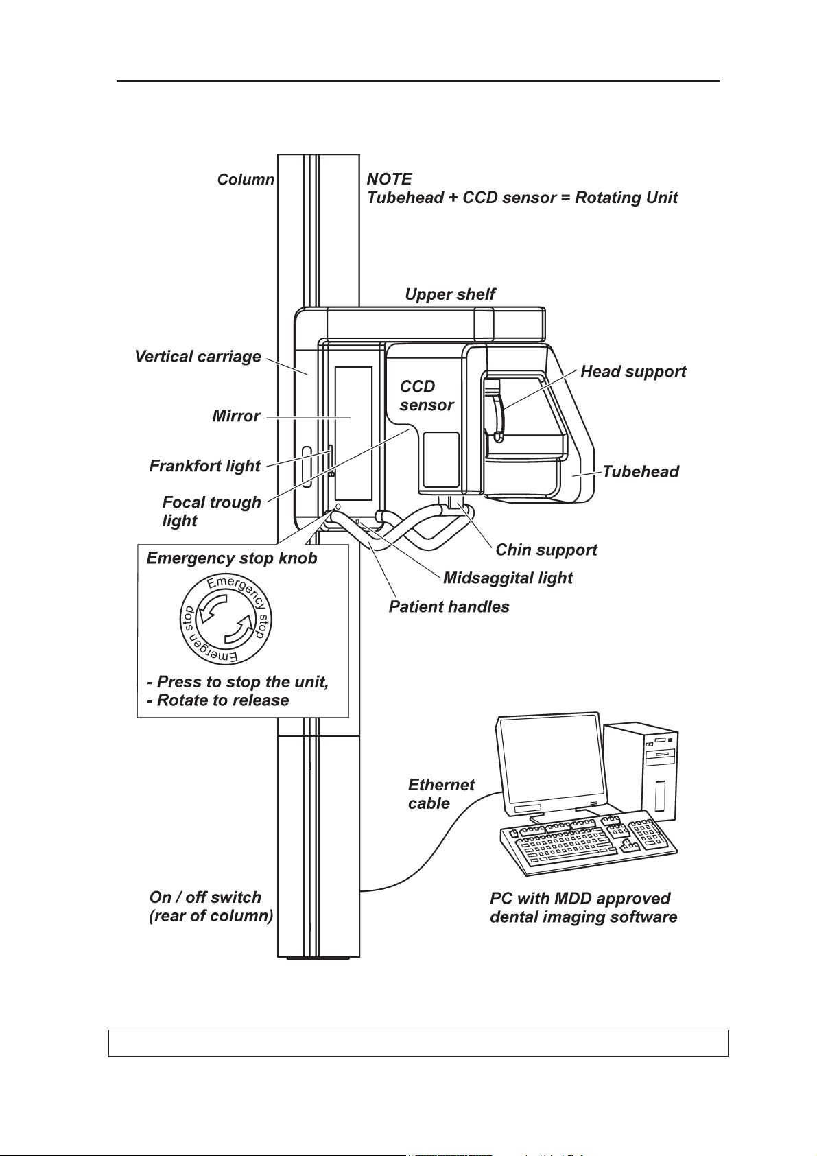
The Cranex Novus is used with a PC in which Digora
for Windows or some other MDD approved dental imaging software is installed.
Page 18
Service Manual 200569 11
Cranex Novus 2. Unit Description
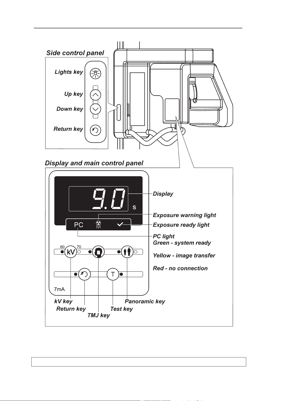
2.2 The main parts and assemblies
Page 19
12 Service Manual 200569
2. Unit Description Cranex Novus
Page 20
Service Manual 200569 13
Cranex Novus 2. Unit Description
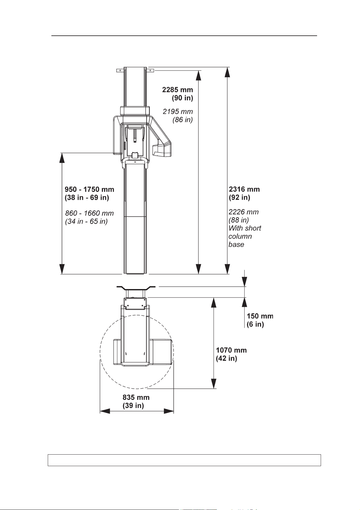
2.3 Unit dimensions
Page 21
14 Service Manual 200569
2. Unit Description Cranex Novus
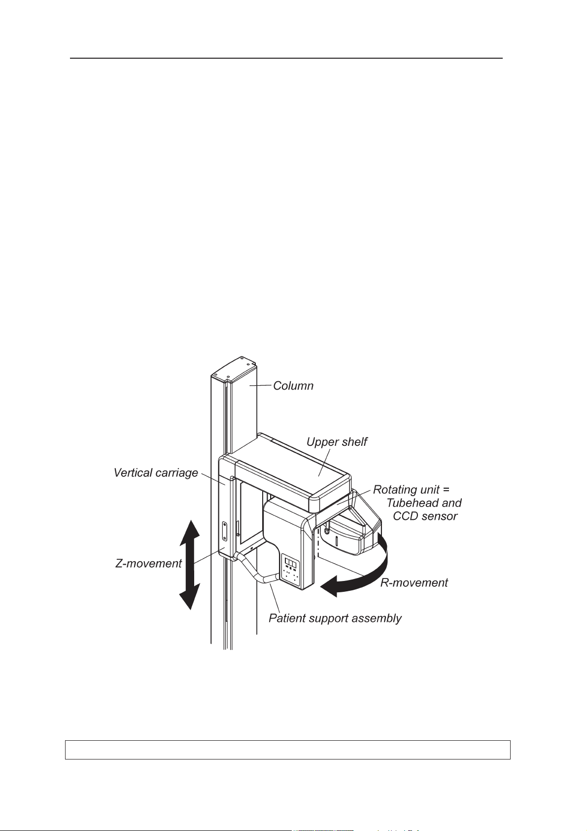
2.4 Mechanical description
The unit comprises a column, a vertical carriage, an
upper shelf, a rotating unit and a patient support assembly.
The column rests on the fl oor and is fi xed to the wall
using wall bracket. If the unit is used in areas prone to
earthquakes the base of the column MUST also be
fi xed to the fl oor.
If the unit needs to be free standing it can be attached
to the show stand (part no. 9802666).
The vertical carriage is attached to the column and
can slide up and down the column (Z-movement, for
unit height adjustment). The upper shelf is attached to
the top of the vertical carriage.
The rotating unit, which comprises the tubehead and
collimator and the CCD sensor assembly, is attached
to the underside of the upper shelf. The rotating unit
rotates to take panoramic exposures (R-movement).
Page 22
Service Manual 200569 15
Cranex Novus 2. Unit Description
Inside the tubehead there is the x-ray tube. It is a fi xed
tungsten anode type with a focal spot of 0.5 mm. The
maximum anode voltage is 70kV and maximum current
is 7mA.
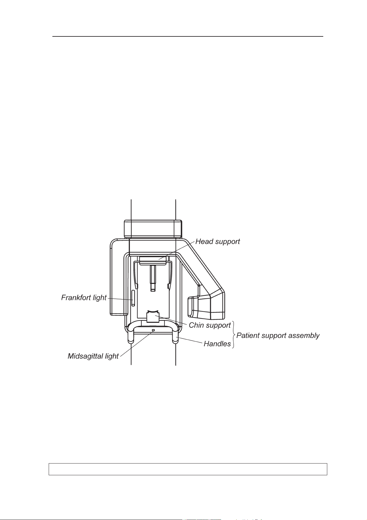
The patient support assembly is attached to the bottom of the vertical carriage. It comprises handles for
the patient to hold and a chin support.
The patient is held in position with a four-point support
system. The head support (attached to the rotating
unit) supports the patient's head with temple supports
and the forehead support. The patient support assem-
bly supports the patients lower jaw on the chin support,
using either the chin rest or lip support.
There are two patient positioning laser lights, midsagit-
tal light and Frankfort (horizontal) light.
Page 23

16 Service Manual 200569
2. Unit Description Cranex Novus
2.5 Electrical description
Circuit boards
Circuit boards are described in detail in section 3. Circuit Boards.
Power supply
Power (230VAC or 115VAC) is supplied to the unit
through L100 (Z-Motor Driver). From L100, power is
routed through the Generator board to a transformer
which produces low voltages (+3, +3.3, +5, -9.4, +15
and +24V) that are supplied to L200, a linear mode
power supply, which distributes the voltages to the
other boards in the unit. The transformer also produces
27VAC and 19VAC voltages that are supplied directly
(not through L200) to the Generator board.
The power for the AC-motor (z-motor), 230VAC or
115VAC, is taken directly from L100 and not from the
Generator board.
Capacitors on the Generator board produce the 310V
needed to power the tubehead from the 230VAC or
115VAC supplied by L100.
Main fuses
Two 5AT/230VAC or 8AT/115VAC, dimensions 5mm x
20mm, UL approved.
They are located below the main power supply cable at
the rear of the column.
Page 24

Service Manual 200569 17
Cranex Novus 2. Unit Description
Unit control
The unit is controlled by a microprocessor on L400
(CPU board). It continually monitors and controls the
operation of the unit. A serial peripheral interface communication protocol (SPI - RS485) and direct digital I/O
are used to monitor most of the unit functions.
The microprocessor:
- monitors the optosensors
- monitors control panel keys
- controls unit movements during exposures
- starts, controls and stops x-ray generation
- controls the digital imaging chain
The necessary unit settings and parameters for all the
imaging programs are stored in the memory which is
also on L400.
Motors and motor control
There is one stepper motor and one AC-motor in the
unit.
The stepper motor drives the rotating unit (R-movement). The stepper motor is driven and controlled by
L300 (3-Phase Microstepper Driver).
The AC-motor (Z-motor) adjusts the height of the unit
(Z-movement), and the motor is activated by L100. To
activate the Z-motor L100 must receive a control signal
from L400 and a separate control (enable) signal from
the Z-movement (up/down) keys.
An emergency switch on the front of unit disables the Zmotor (Z-movement) and stepper motor (R-movement)
when pressed.
Page 25
18 Service Manual 200569
2. Unit Description Cranex Novus
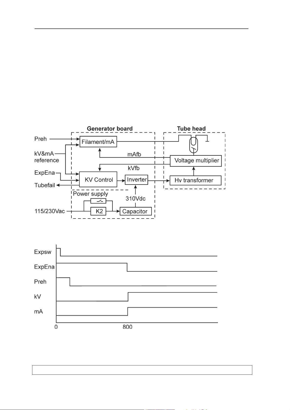
Exposure logic
An exposure can only be taken when the unit is in the
ready state (the exposure ready light on the control
panel is on) and the exposure button is pressed and
held down.
The Generator board receives the correct kV and mA
references from the CPU (L400). A few milliseconds
after the exposure button is pressed (Expsw) preheat
is enabled (Preh). After 800ms the exposure will start
(ExpEna). The tubehead will receive power from the
Generator board and the Generator board will also start
to regulate the mA and kV according to mA- and kVfeedback.
Page 26

Service Manual 200569 19
Cranex Novus 2. Unit Description
Position control
The position of the rotating unit (R-movement) is monitored by optosensors on N2500 (Rotation Position Sensor Circuit). The optosensors indicate in which sector
the rotating unit is. The optosensors ensure that the
rotating unit is in the correct position, start or PIO (Patient In/Out), for an exposure.
The statuses of the optosensors are monitored continually by the unit software.
The upper and lower limits of the vertical carriage (Zmovement) are monitored by microswitches.
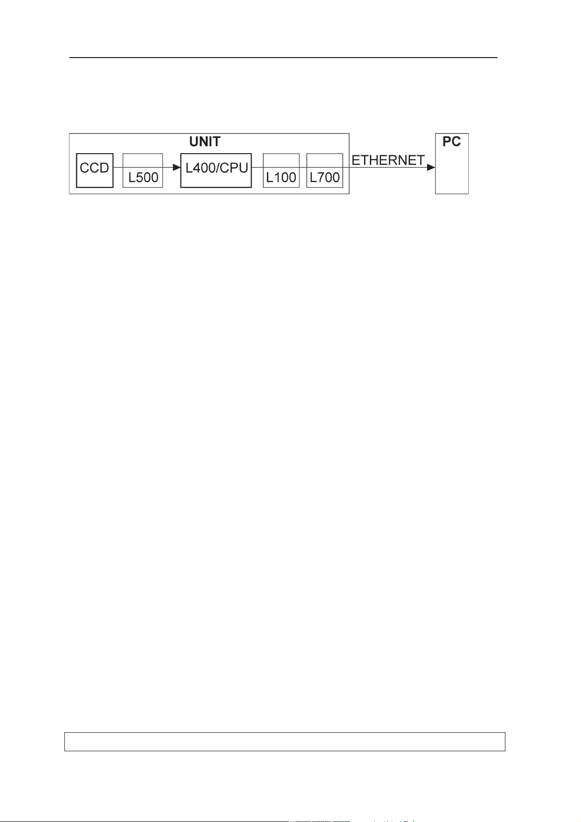
A overview of the Imaging Chain
This description assumes that the unit is ready to take
an exposure.
Image acquisition is controlled by a software component, Digora Software Driver (DSD) which is installed in
the PC connected to the unit.
When an exposure is taken L400 (the CPU) then sends
a PPOWER (pan) and CCDON signal. CCDON signal
activates
linear regulators on L200 which then produce
the power supply voltages for the CCD sensor.
The CPU's control software continuously monitors the
status of the connection with the DSD driver. After image exposure but before image transfer the CPU sends
a label that includes the imaging parameters (—kV/—
mA/ —s) and an imaging program identifi er.
The CPU enables the IMAGE signal to activate pixel
clocking. The CPU then produces the TDI clock signal,
which clocks the pixels from the CCD sensor. Derivation
of several CCD clock signals from the TDI clock is done
by the CCD sensor board.
Radiation striking the CCD sensor is converted to visible light which is detected by the CCD cell. A binning
procedure is carried out on individual pixels, i.e. two adjacent pixels in a row and column (2 x 2 binning) forms
one large pixel (96µm x 96µm). The output voltage of
the CCD is fed to a 14-bit A/D converter.
Page 27
20 Service Manual 200569
2. Unit Description Cranex Novus
The CCD sensor board sends the image data (now 12
bits) to the CPU board where they are saved on the
SDRAM. The image information is transferred to the PC
via the Ethernet cable.
In the PC there is a Network Interface Card (NIC). After
image data transfer the DSD preprocesses the raw
image, for example it interpolates gaps between CCD
chips, and carries out dark current correction and gain
correction (the pixels do not have equal characteristics).
Page 28
Cranex Novus 1. General information
M
PC
CCD SENSOR 200394
GND40
39 GND
GND38
37 GND
uC+3.3V36
35 uC+3.3V
34
33
PAN_CAM_DET32
31 PAN_CAM_DET
30
29
28
27
RESET
26
25 CTXD
CRXD24
GND23
22
GND21
GND20
19 DS
18 GND
17
PPOWER16
15 TDICLK
14 IMAGE
13
VV12
11 HL
10
9
D58
76D4
D3
D2
D1
D0
GND
GND
5
4
3
2
1
X190
PINHEADER 2 x 20
L700 INTERFACE BOARD 200401
5
4
GND
EXPLT3
2 READYLT
EXPSW_LOCK
1
6
J701
RJ-12
J703
J705
RJ-45
6
7
8
1 TP0+
TP0-2
3 TP1+
TP1-
4
5
1EXPSW
READYLT2
3EXPLT
GND4
AMP MODU II B-1X6M
Molex 95009-2661
PINHEADER 2 x 8
13 +5V
+5V14
1516GND
GND
-9V
-9V1211
10 +3V
+3V9
8 +15V
+15V7
X191
1GND
GND2
3GND
GND4
56+3.3V
+3.3V
Cranex Novus Wiring Diagram v1.1 17.03.2008
5
6
GND
L100 Z-MOTOR DRIVER 200395
GND
GND
EXPLT
READYLT
EXPSW
16
15
14
13
12
11
J116
ZACT
RETURN2
ZENA
ESTOP
+5V
1
2
3
4
5
+5V
6
7
8 MIRRORSW
9
10
AMP MODU II 2x8M
GND2
1
ZTOP
ZBOTTOM
1
2GND
J102
J103
AMP MODU II 1x2M
AMP MODU II 1x2M
6
ZDOWN
5
4
3
2
1
ZUP
ZACTIN
RETIN
AMP MODU II 1x6M
J100
PLIN
GND
AMP MODU II 1x2M
J101
GND2
1
MSW
GND
EXPLT
EXPSW
READYLT
1
2
3
4
J111
J112
MOLEX RJ-45
6
7
8
1 TP0+
TP0-2
3 TP1+
TP1-
4
5
4
TP1+3
2 TP0-
TP0+1
J113
5
6
GND
67TP1-
5
PLENA
PLSW
GND
8
J110
ESTOP_5V2
1
+5V
4
AC1TR6OUT3
2
AC1TR4OUT1
J104
AMP MODU I 1x8M
67AC2TR5OUT
5
8
AMP FASTON TAB CONTACT
J105
AC12
1
AC1
J106
AC22
1
AC2
J108
POSLOUT2-2
1
ESTOP_5V
J114
AC12
1
AC1
J115
AC2
2
1
AC2
AMP FASTON TAB CONTACT
AMP MODU II 1x2M
AMP MODU II 1x2M
AMP MODU II 1x6M
MOLEX RJ-45
AMP FASTON TAB CONTACT
AMP FASTON TAB CONTACT
GND
N2500 ROTATION POSITION SENSOR
4
3
2
+5V1
ROTSW1
ROTSW2
J2501
AMP MODU II B-1x4M
(280371-2)
ENA
(280385-2)
AMP MODU II 2x8M
+5V
AMP MODU II 1x4M
J302
Phase #3
Phase #2
1Phase #1
2
3
4
16
GND
15
14
13
GND
12
DIR
11
GND
L300 3-PHASE MICROSTEP DRIVER 200397
J301
CLK
GND
GND
+24V
+24V
1
2
3
4
5
PGND
PGND
6
7
8 HICUR
9
10
(280371-2)
2GND
+5V1
AMP MOD I 1x2M
J205
TP0+1
2 TP0-
TP1+3
4 TP1-
J204_CPU
AMP MODU II 1x4M
J3
PINHEADER 2x25
GND50
49 +3.3V
EXPSW
48
47 HL
PLSW46
45
44
43 TUBEFAIL
MIRRORSW42
41 ZACT
J203_CPU
PINHEADER 2x20
1
2
3
4
5
TUBEHEAT
A/D_1
LINEOK6
7
8MAFB
9
10 KVFB
11
12 GND
GND13
GND14
GND15
16 GND
GND17
GND18
GND19
20 +5V
21 +5V
22 +5V
23 +5V
24 +5V
25
26 ZENA
RESET_CCD
27
28 PL_ENA
HICUR
29
30 FAN_PWM
OUT131
32 OUT2
OUT333
34 ROTSW1
ROTSW235
36 RXD
MISO37
38
39
40
GND40
39 +5V
GND38
37 ENA
GND36
35 DIR
GND34
33 CLK
PPOWER32
31 CCDENA
TXD30
29 TDI_CLK
A/D_228
27 IMAGE
GND26
25 EXPON
PREH
24
KV_REF23
MA_REF22
BEEP21
GND20
19 CS
18 GND
17 SCLK
GND16
15 MOSI
14 GND
13 REGTEMP
D512
11 D4
D310
D29
D18
76D0
GND
DS
GND
VV
GND
+5V
5
4
3
2
1
L400 CPU BOARD 200398
(280370-2)
(280371-2)
(280610-1)
(280373-2)
FANPWM
LINEOK (U_IN)
L200 CCD POWER SUPPLY 200396
4
3
9V AC (-)
9V AC (+)
6
5
4
8V AC (+)
8V AC (-)3
2
18V AC (+)
18V AC (-)1
MOLEX 5566-06A
J205
2GND
+24_RAW1
AMP MODU II 1x2M
J207
J201
AMP MODU I 1x4M
1 +5.0VD1
GND2
8
7
J204
AMP MODU II 1x8M
1 +5.0VD2
GND2
3 +3.3VD_CCD
GND4
56REGTEMP
CCDENA
13 +5.0V_CCD
+5.0V_CCD14
1516GND
GND
-9V_CCD
-9V_CCD
12
11
10 +3.0V_CCD
+3.0V_CCD9
8 +15V_CCD
+15V_CCD7
J202
1GND
GND2
3GND
GND4
56+3.3V_CCD
+3.3V_CCD
4GND
GND3
2 +24V_STEP
+24V_STEP1
AMP MODU II 1x4M
J206
(280379-2)
Yamaichi FAP-16-08-2-2-0af
AMP MODU II 1x6M 90
J602
1
2
3
4
5
6
kV
TEST
TMJ
RETURN1
PATIENT_SIZE
GND
RIBBON CABLE CONNECTOR
16
15
14
13
12
11
GND
GND
GND
GND
GND
+5V
RETURN2
GND
READYLIGHT
MISO
MOSI
CS
SCLK
BEEP
+5V
DIG4
L600 CONTROL PANEL 200400
10
9
8
7
6
5
4
3
2
1
J601
(280372-2)
AMP MODU II B-1x2M
1EXPSW
EXPSW_LOCK2
J702
(280370-2)
GND
5
4
GND
EXPLT3
2 READYLT
EXPSW_LOCK
1
6
RJ-12
J704
Molex 95009-2661
GND
Molex 95009-2881
J706
RJ-45
6
7
8
1 TP0+
TP0-2
3 TP1+
TP1-
4
5
Molex 95009-2881
(280371-2)
FILAMENT VOLTAGE (-)
10
FILAMENT VOLTAGE (+)9
GND8
GND7
6GND
GND5
MAFB4
KVFB1
GND2
3 HEATCURRENT
MOLEX 90136-1210
X50
HV2
MOLEX 5566-02A
X48
HV1
1
2
27V AC (-)
27V AC (-)3
4
27V AC (+)
MOLEX 5566-04A
X43
27V AC (+)1
2
19V AC (-)
MOLEX 5566-02A
X44
19V AC (+)1
2
MOLEX 5566-04A
X47
L
N1
2
3
4
N
L
KVFB
KVFB
MOLEX 87089-2016
X49
TUBEHEAT20
19 TUBEHEAT
MAFB18
MAFB17
GND
KVPWM
EXPENA
TUBEFAIL
1
2
3
4
5
TUBEFAIL
EXPENA
KVPWM6
7
8GND
9
10
GND11
12 GND
PREH
13
PREH
14
MAPWM15
16 MAPWM
GENERATOR BOARD 200404
TUBE HEAD ASSEMBLY
L
5
6
MOLEX 5566-06A
X45
1
2
3
4
N
(62409-1)
(62409-1)
(280370-2)
(280370-2)
(280612-1)
(280370-2)
(280370-2)
(280370-2)
(280372-2)
(95052-2887)
(95052-2887)
(280372-2)
(280385-2)
(62409-1)
(62409-1)
LINEOK
CCDENA
5 REGTEMP
6
7
8
FANPWM
(280373-2)
AMP MODU II 1x8M
J506
+3.3VD_CCD
GND
1 +5.0VD2
2
3
4
GND
+3.3VD_CCD
(280371-2)
GND
PLSW
PL_ENA
(280385-2)
(280373-2)
ENA
DIR
6
5
4GND
CLK
3
2GND
HICUR
1
AMP MODU II 1x8M
J502
7
8
+5.0VD2
GND
KVFB
KVFB
RIBBON CABLE
16
15
14
13
12
11
GND
GND
GND
GND
GND
+5.0VD2
RETURN2
GND
READYLT
MISO
MOSI
CS
SCLK
BEEP
+5.0VD2
DIG3
10
9
8
7
6
5
4
3
2
1
J507
AMP MODU II 1x4M
J504
ROTSW2
ROTSW1
1 +5.0VD2
2
3
4
GND
RIBBON CABLE (1mm)
GND
GND
EXPLT
READYLT
EXPSW
16
15
14
13
12
11
J503
ZACT
RETURN2
ZENA
ESTOP
+5.0VD2
1
2
3
4
5
+5.0VD2
6
7
8 MIRRORSW
9
10
AMP MODU II 2x8M
1
2
3
4
5
GND
GND
D0
D1
D2
D3D46
7
8D5
9
10
HL11
12 VV
13
IMAGE_OUT14
TDICLK_OUT15
16 PPOWER_OUT
17
GND18
DS19
20 GND
21 GND
22
23 GND
24 TXD_OUT
RXD25
26 RESET_CCD
27
28
29
30
PAN_CAM_DET31
32 PAN_CAM_DET
33
34
+3.3VD_CCD35
36
GND37
38 GND
GND39
40 GND
J505
MAPWM16
15 MAPWM
14 PREH_2
13 PREH_2
GND12
11 GND
10
9
GND8
7
6KVPWM
EXPENA
TUBEFAIL
5
4
3
2
1
TUBEFAIL
EXPENA
KVPWM
GND
17 MAFB
18 MAFB
TUBEHEAT19
20 TUBEHEAT
J501
40
39
38
37 MISO
RXD36
35 ROTSW2
ROTSW134
33
32
31
FANPWM30
29 HICUR
PL_ENA28
27 RESET_CCD
ZENA26
25
24
23
22
21
20
19 GND
18 GND
17 GND
GND16
15 GND
14 GND
13 GND
GND12
11
KVFB_OUT10
9
MAFB_OUT8
7
6LINEOK
TUBEHEAT_OUT
5
4
3
2
1
ZACT
41
42 MIRRORSW
TUBEFAIL
43
44
45
46 PLSW
HL47
48 EXPSW
49
50 GND
PINHEADER 2x25
J508
PINHEADER 2x20
J509
1
2
3
4
5
GND
VV
GND
DS
GNDD06
7
8D1
9D2
10 D3
D411
12 D5
(A/D_1)13
GND14
MOSI15
16 GND
SCLK17
GND18
CS
19
20 GND
21 BEEP
22 MA_REF
23 KV_REF
24 PREH
EXPON25
26 GND
IMAGE27
28 REGTEMP
TDI_CLK29
30 TXD
CCDENA31
32 PPOWER
CLK_1
33
34 GND
DIR
35
36 GND
ENA_1
37
38 GND
39
40 GND
L500 CONNECTOR BOARD 200399
MEMBRANE
STRAIGHT 2mm
PINHEADER 2 x 8
STRAIGHT 2mm
STEPPER
SIDE CONTROL
EMERGENCY
SWITCH
AC-MOTOR
KEY LOCK
MICRO
SWITCH
MICRO
SWITCH
MICRO
SWITCH
J109
POSLOUT1-2
1
ESTOP_5V
AMP MODU II 1x2M
(280370-2)
LASER #1
LASER #2
MAINS SWITCH
EXPOSURE SWITCH
EXTERNAL
LIGHTS
MOTOR
PINHEADER 2 x 20
STRAIGHT 2mm
STRAIGHT 2mm
MIRROR
ZUP
ZDOWN
PaloDEx Group Oy
PANEL
+5V
+5V
+5V
+5V
+5V
+5V
+5V
(230V setup)
Cascade Board
X-Ray Tube
Y-Cable
M
L
5
6
MOLEX 5566-06A
X46
1
2
3
4
N
(115V setup)
L
N
+310V DC
18VAC / 9VAC / 8VAC
SWITCHES
SWITCHES
230/115 VAC
Fuses: 2 x T5L 250V (for 230V device)
2 x T8L 250V (for 115V device)
L (230/115 VAC)
N
ETHERNET
ETHERNET
230/115 VAC
MAINS TRANSFORMER
230VAC: 2 prim windings
115VAC: 1 prim winding
ETHERNET
18VAC 9VAC 8VAC
27VAC
19VAC
115VAC 115VAC
MAINS FILTER
2 OPTO SENSORS
7-segment display
L
NN
L
N
L
FAN
24V DC
1
2
3
4
5
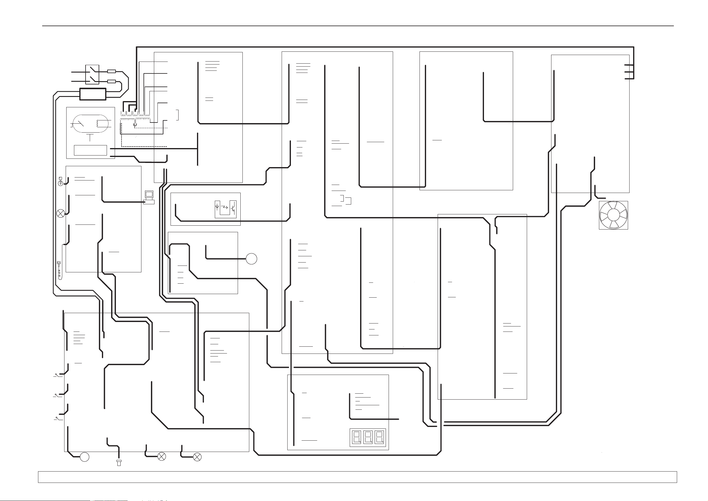
2.6 Wiring diagram - overview
Service manual 200569 21
Page 29
1. General Information Cranex Novus
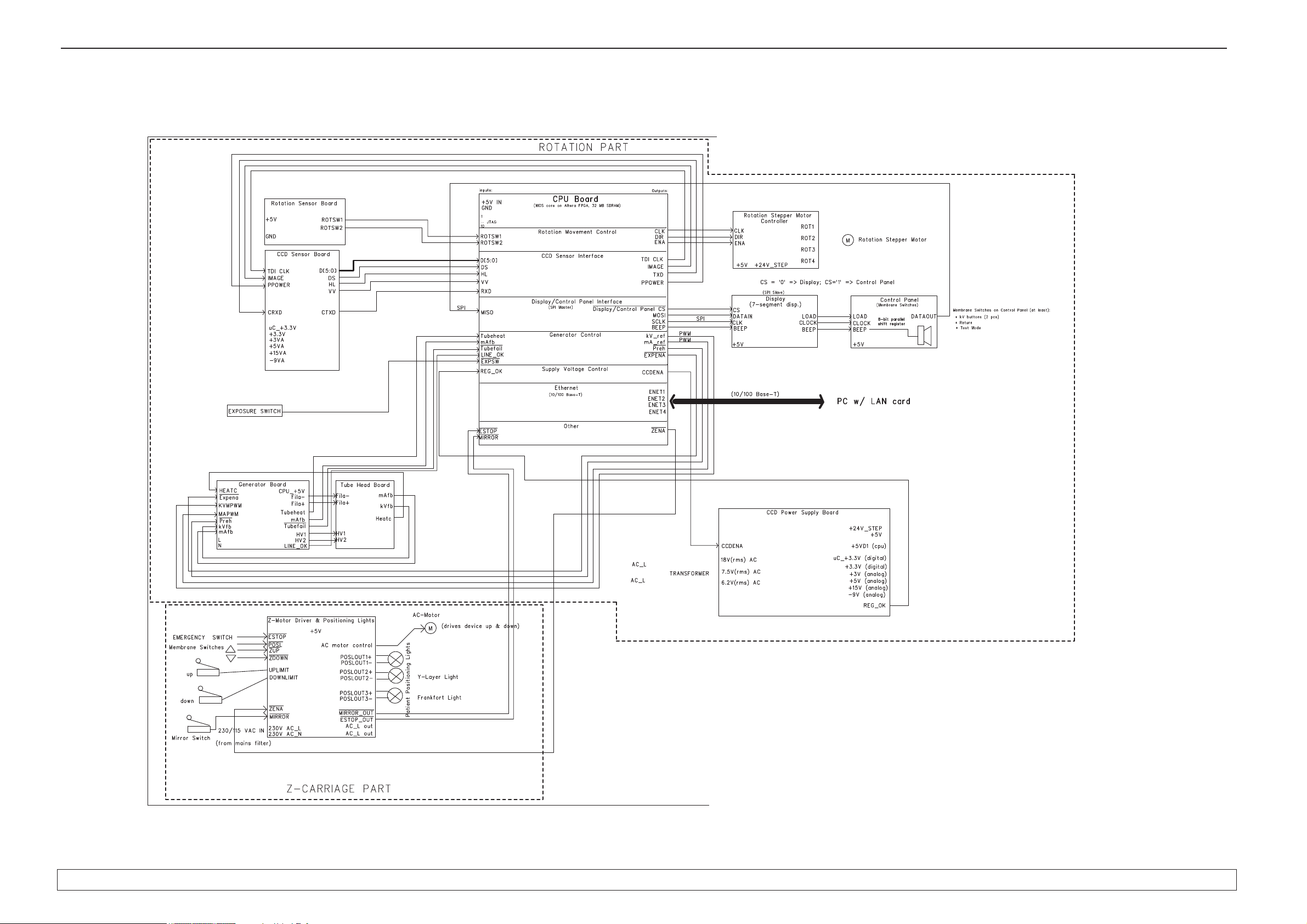
2.7 Block diagram
22 Service manual 200569
Page 30
Cranex Novus 1. General information
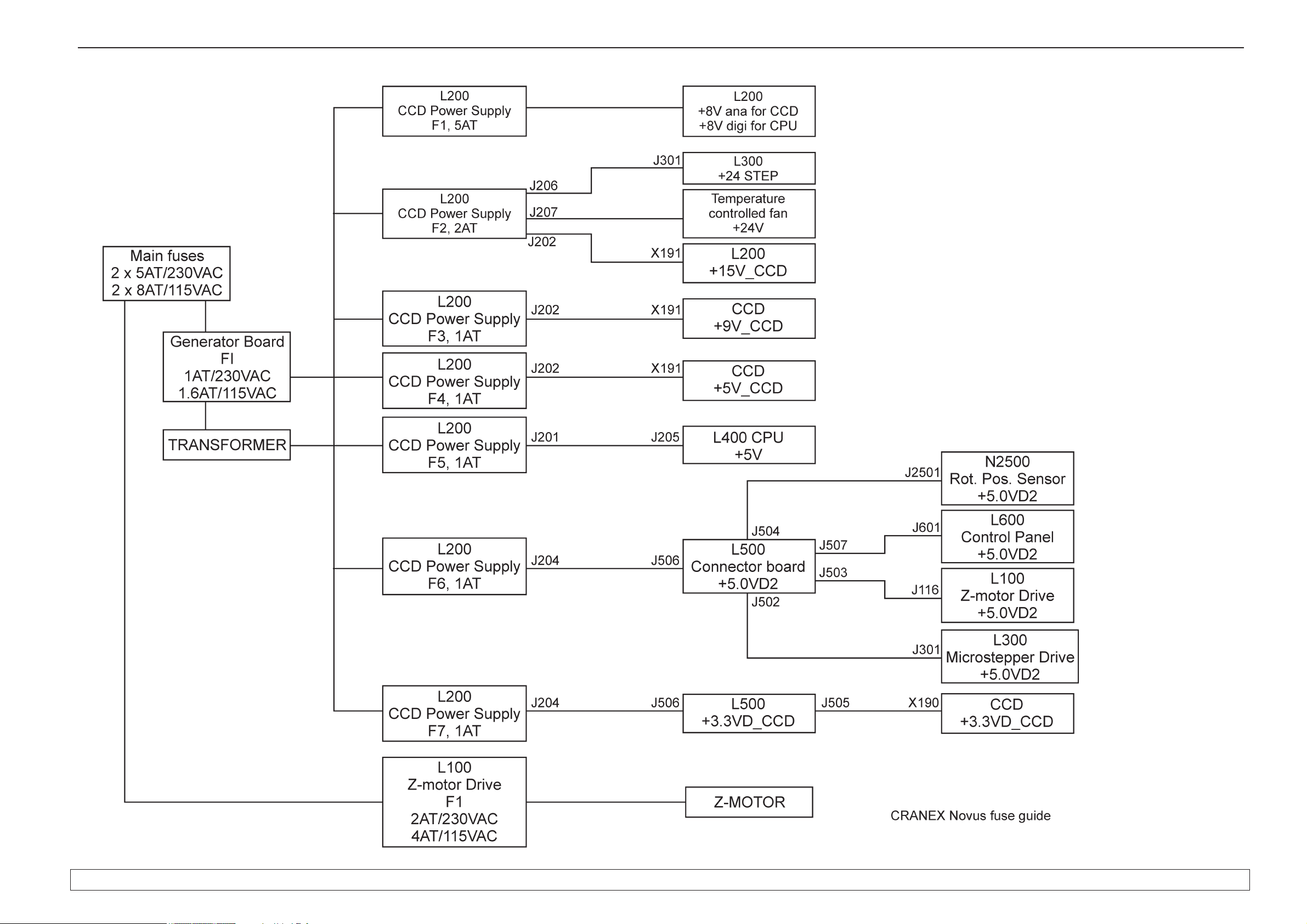
2.8 Fuse diagram
Service manual 200569 23
Page 31

1. General Information Cranex Novus
24 Service manual 200569
Page 32

Cranex Novus 3. Circuit Boards - L100, Z-Motor Driver
Service manual 200569 25
3. Circuit Boards
NOTE: An asterisk (*) after a signal name indicates an active low-level signal.
3.1 L100, Z-Motor Driver (Pt. no. 200395)
L100 - Location
On the upper shelf.
To access remove front panel and then top cover plate
(see section 7.1).
Page 33

26 Service manual 200569
3. Circuit Board - L100, Z-Motor Driver Cranex Novus
L100 - Field replaceable parts
Fuse F1.
NOTE:
The fuses used MUST be the approved type, UL listed
and CSA certifi ed.
Approved fuses:
- for units rated 230VAC:
2AT/250VAC Cooper Bussmann MDL-2
or SIBA ELU 70 065 65.
- for units rated 115VAC:
4AT/250VAC Cooper Bussmann MDL-4
or SIBA ELU 70 065 65.
Dimensions 6.3 mm x 32 mm.
L100 - Description
L100 (Z-motor Driver) controls the AC-motor that drives
the unit up and down. Membrane switches on the side
of the vertical carriage are used to activate the ACmotor. The positions of the Z-carriage and the Rotating
Unit are also monitored by L100.
Micro switches at the top and bottom of the column
monitor the upper and lower positions of the Z-movement. Based on the logic on the circuit board, the movement of the AC motor is enabled or prohibited. Three
triacs control the Z-motor currents. Outputs are optocoupled from the user inputs with TLP3063 circuits. The
board also includes light controls for the laser positioning lights.
Page 34

Cranex Novus 3. Circuit Boards - L100, Z-Motor Driver
Service manual 200569 27
L100 - Block diagram
Page 35

28 Service manual 200569
3. Circuit Board - L100, Z-Motor Driver Cranex Novus
L100 - Indicator lamp
Lamp Function Indicates
LA1 GLIM AC indicator lamp L100 receiving 230 or 115VAC line voltage.
L100 - Indicator LEDs
LED Colour Indicates
D1 green +5V on
D2 green ZACT-movement key pressed
D3 green ZON on
D4 red ESTOP on. Emergency stop button is on.
L100 - Test Points
Number Signal Value
TP1 ESTOP_5V +5V normally, 0 ... +0.5V when emergency
switch pressed down
TP2 ZDIR 0V driving up, +4.8V...+5V driving down
TP3 ZON Text wrong (+5V). Correct value +3V when
up/down key pressed. Otherwise 0V.
TP4 +5V +5V
TP5 GND 0V
TP6 ZACT* 0 ... +0.5 when up/down key pressed,
otherwise close to +5V.
L100 - Test Switches
DANGER - HIGH VOLTAGE!
Take great care when pressing the switches SW1, SW2, SW3 not to touch
indicator lamp LA1 which is 230 / 115VAC.
Switch Operation
SW1
SW1 + SW2 Press simultaneously to drive vertical carriage up.
SW2
SW2 + SW3 Press simultaneously to drive vertical carriage down.
SW3
Page 36

Cranex Novus 3. Circuit Boards - L100, Z-Motor Driver
Service manual 200569 29
L100 - Connectors
J100
Pin Signal Description
1 ZUP* Z-movement drive up key pressed
2 ZDOWN* Z-movement drive down key pressed
3 ZACTIN* Z-movement key pressed
4 PLIN* Position lights key pressed
5 RETIN* Return key pressed
6 GND GND (logic)
J101
Pin Signal Description
1 MSW* Mirror switch
2 GND GND (logic)
J102
Pin Signal Description
1 ZTOP Z-movement reached top
2 GND GND (logic)
J103
Pin Signal Description
1 ZBOTTOM Z-movement reached bottom
2 GND GND (logic)
J104
Pin Signal Description
1 AC1TR4OUT AC motor power signals
3 AC1TR6OUT AC motor power signals
6 AC2TR5OUT AC motor power signals
J105
Pin Signal Description
1,2 AC1 230 or 115 VAC line voltage
Page 37

30 Service manual 200569
3. Circuit Board - L100, Z-Motor Driver Cranex Novus
J106
Pin Signal Description
1,2 AC2 230 or 115 VAC line voltage
J107
Pin Signal Description
1 ESTOP_5V Emergency stop
2 POSLOUT3* Position light 3
J108
Pin Signal Description
1 ESTOP_5V Emergency stop
2 POSLOUT2* Position light 2
J109
Pin Signal Description
1 ESTOP_5V Emergency stop
2 POSLOUT1* Position light 1
J110
Pin Signal Description
1 +5V Supply voltage (logic)
2 ESTOP_5V Emergency stop
J111
Pin Signal Description
1 EXPSW* Exposure switch
2 READYLT Ready light
3 EXPLT Exposure light
4,6 GND GND (logic)
J112
Pin Signal Description
1 TP0+ Ethernet, twisted pair 0
2 TP0- Ethernet, twisted pair 0
3 TP1+ Ethernet, twisted pair 1
6 TP1- Ethernet, twisted pair 1
Page 38

Cranex Novus 3. Circuit Boards - L100, Z-Motor Driver
Service manual 200569 31
J113
Pin Signal Description
1 TP0+ Ethernet, twisted pair 0
2 TP0- Ethernet, twisted pair 0
3 TP1+ Ethernet, twisted pair 1
6 TP1- Ethernet, twisted pair 1
J114
Pin Signal Description
1,2 AC1 230 or 115 VAC line voltage
J115
Pin Signal Description
1,2 AC2 230 or 115 VAC line voltage
J116
Pin Signal Description
1,2 +5V Supply voltage (logic)
3 ESTOP* Emergency stop on
4 PLENA Position lights enable
5 ZENA* Z-movement enable
7 RETURN2* Rotating unit return
8 MIRRORSW Mirror switch
9 ZACT* Z-movement activity
10 PLSW Position light switch
11 EXPSW* Exposure switch
12,15,16 GND GND (logic)
13 READYLT Ready light on
14 EXPLT Exposure light
Page 39

32 Service manual 200569
3. Circuit Board - L100, Z-Motor Driver Cranex Novus
Page 40

Cranex Novus 3. Circuit Boards - L100, Z-Motor Driver
Service manual 200569 33
Page 41

34 Service manual 200569
3. Circuit Board - L100, Z-Motor Driver Cranex Novus
Page 42

Cranex Novus 3. Circuit Boards - L200, CCD Power Supply
Service manual 200569 35
3.2 L200, CCD Power Supply (Pt. no. 200396)
L200 - Location
In the rotating unit on the the CCD sensor side.
To access remove side cover left and the EMC shield
(see section 7.1).
Page 43

36 Service manual 200569
3. Circuit Boards - L200, CCD Power Supply Cranex Novus
L200 - Field replaceable parts
Fuse 1, 2 and 3
NOTE:
The fuses used MUST be the approved type, UL listed
and CSA certifi ed.
Fuse F1, 5AT/250VAC Cooper Bussmann S506-series
Fuse F2, 2AT/250VAC Cooper Bussmann S506-series
Fuse F3, 1AT/250VAC Cooper Bussmann S506-series
Dimensions, 5mm x 20mm.
L200 - Description
L200 supplies different voltages to most of the circuit
boards in the unit. L200 receives three transformed AC
voltages (18VAC, 9VAC, and 8VAC) from the Generator
board, and rectifi es and regulates them to produce the
various voltages that the unit requires.
The CCD sensor require +3.3V, +3.3V, +3V, +15V, -9V,
+5V.
The fan (it cools L200) and the 3-phase stepper motor
require 24V.
L400 and pheripheral electronics require two regulated
5VDC power supplies.
Page 44

Cranex Novus 3. Circuit Boards - L200, CCD Power Supply
Service manual 200569 37
L200 - Block diagram
Page 45

38 Service manual 200569
3. Circuit Boards - L200, CCD Power Supply Cranex Novus
L200 - Indicator LEDs
LED Colour Indicates
D1 green +5.0VD1 on
D2 green +5.0VD2 on
D3 green +3.3VD_CCD on
D14 green +15V on
D15 green +3.0V_CCD on
D16 green +5.0V_CCD on
D23 green +3.3V_CCD on
D33 green +15V_CCD on
L200 - Test Points
Number Description Value
TP1 GND (logic) 0V
TP2 +24V +24V
TP5 +5.0VD1
TP6 GND (logic) 0V
TP7 +3.0V_CCD
TP8 +5.0V_CCD
TP9 +3.3V_CCD
TP10 +8V_RAW
TP11 +5.0VD2
TP12 +15V
TP13 FAN VOLTAGE >20V
TP14 +3.3V_CCD
TP16 CCDENA 5V on, 0V off
TP17 -9.4V_CCD
TP18 U_IN Between 2.2V and 2.8V
L200 - Connectors
J201
Pin Signal Description
1 +5.0VD1 Supply voltage (L400 CPU)
2 GND GND (logic)
Page 46

Cranex Novus 3. Circuit Boards - L200, CCD Power Supply
Service manual 200569 39
J202
Pin Signal Description
1-4,15,16 GND GND (logic)
5,6 +3.3V_CCD Continuous supply voltage (CCD)
7,8 +15V_CCD Supply voltage (CCD)
9,10 +3.0V_CCD Supply voltage (CCD)
11,12 -9V_CCD Supply voltage (CCD)
13,14 +5.0V_CCD Supply voltage (CCD)
J204
Pin Signal Description
1 +5.0VD2 Supply voltage (logic)
2,4 GND GND (logic)
3 +3.3V_CCD Continuous supply voltage (CCD)
5 REGTEMP Regulator temperature
6 CCDENA CCD sensor supply voltage, +5V when active
7 U_IN Line voltage peak level detection
8 FANPWM Temperature controlled fan
J205
Pin Signal Description
1,4 18 VAC Transformer secondary voltage
2,5 9 VAC Transformer secondary voltage
3,6 8 VAC Transformer secondary voltage
J206
Pin Signal Description
1,2 +24V_STEP Supply voltage (stepper motors)
3,4 GND GND (logic)
J207
Not used
J208
Pin Signal Description
1 FAN Supply voltage (temperature controlled fan)
2 GND GND (logic)
Page 47

40 Service manual 200569
3. Circuit Boards - L200, CCD Power Supply Cranex Novus
Page 48

Cranex Novus 3. Circuit Boards - L200, CCD Power Supply
Service manual 200569 41
Page 49

42 Service manual 200569
3. Circuit Boards - L200, CCD Power Supply Cranex Novus
Page 50

Cranex Novus 3. Circuit Boards - L200, CCD Power Supply
Service manual 200569 43
Page 51

44 Service manual 200569
3. Circuit Boards - L300, 3-Phase Microstepper Driver Cranex Novus
3.3 L300, 3-Phase Microstepper Driver (Pt. no. 200397)
L300 - Location
Inside the rotating unit, above the head support. To access, remove the head support, lower protective cover
and then the left aperture cover (see section 7.1).
L300 - Field replaceable parts
None.
Page 52

Cranex Novus 3. Circuit Boards - L300, 3-Phase Microstepper Driver
Service manual 200569 45
L300 - Description
L300 controls the 3-phase stepper motor that drives the
Rotating Unit. The board receives in three control signals: clock, dir, and ena. It produces phase voltages for
the stepper motor windings.
L300 - Indicator LEDs
LED Colour Indicates
D1 green +5V on
D2 green +24V on
L300 - Test Points
Number Description Value
TP1 GND 0V
TP2 VREF 0.97V ±0.1V; when HICUR* = '1'
1.95V ±0.1V; when HICUR* = '0' (default value)
TP3 CLK +5V freq <15kHz
TP4 ENA +5V active, 0V idle
TP5 DIR +5V when idle or when moving to the PIO position.
0V when driving to end position.
TP6 PGND 0V
L300 - Connectors
J301
Pin Signal Description
1,3 +24V Power supply
2,4 PGND Power GND
7,9,11,13,15 GND GND (logic)
8 HICUR* High current selection
10 CLK* Stepper motor clock
12 DIR* Stepper motor direction
14 ENA* Stepper motor enabled
16 +5V Power supply (logic)
J302
Pin Signal Description
1 Phase #1 Stepper motor driver's phase voltages
2 Phase #2 Stepper motor driver's phase voltages
3 Phase #3 Stepper motor driver's phase voltages
Page 53

46 Service manual 200569
3. Circuit Boards - L300, 3-Phase Microstepper Driver Cranex Novus
Page 54

Cranex Novus 3. Circuit Boards - L300, 3-Phase Microstepper Driver
Service manual 200569 47
Page 55

48 Service manual 200569
3. Circuit Boards - L400, CPU Board Cranex Novus
3.4 L400 CPU Board (Pt. no. 200398)
L400 - Location
In rotating unit on the the CCD sensor side. To access
remove side cover left and the EMC shield (see section
7.1).
L400 - Field replaceable parts
None.
Page 56

Cranex Novus 3. Circuit Boards - L400, CPU Board
Service manual 200569 49
L400 - Description
The CPU board controls the unit. It controls the rotation and Z movements, the operation of the X-ray tube
and reads the signals from the control panel. It uses an
embedded microcontroller on an Altera Cyclone FPGA
circuit. The board also has an Ethernet transceiver (for
PC connection), I/O buffers, and a 14-bit A/D converter.
The image bits are saved in an SDRAM.
L400 - Indicator LEDs
LED Colour Indicates
D1 green 100-Base-T (100MBit/s) in use
D2 green Ethernet signal activity
D3 green Full Duplex mode in use
D4 green 10-Base-T (10Mbit/s) in use
D6 green +5V on
L400 - Connectors
J203_CPU
Pin Signal Description
1 +5V_CPU Power supply CPU
2,4,6 GND GND (logic)
3 VV Valid video
5 DS Data strobe
7 D0 Data bit 0
8 D1 Data bit 1
9 D2 Data bit 2
10 D3 Data bit 3
11 D4 Data bit 4
12 D5 Data bit 5
13 REGTEMP Temperature of the regulators on L200 board.
14,16,18,20 GND GND (logic)
15 MOSI SPI signal
17 SCLK SPI clock
19 CS* Chip select
21 BEEP Beeper enable
22 mA_ref Current reference
23 kV_ref Voltage reference
24 PREH* Preheat
25 EXPON Exposure on (CPU enabled)
26,34,36,38 GND GND (logic)
27 IMAGE Enables A/D conversion on CCD Sensor Board
28 A/D_2 NOT USED
29 TDI CLK Time Delay Integration Clock (CCD)
30 TXD Transmit data (serial connection)
Page 57

50 Service manual 200569
3. Circuit Boards - L400, CPU Board Cranex Novus
31 CCDENA Enables the supply voltages for the CCD sensor
32 PPOWER CCD sensor's supply voltages are on
33 CLK Stepper motor clock
35 DIR Stepper motor direction
37 ENA Stepper motor enabled
39 +5V_CPU CPU Power supply CPU
40 GND GND (logic)
J204_CPU
Pin Signal Description
1 TP0+ Ethernet, twisted pair 0
2 TP0- Ethernet, twisted pair 0
3 TP1+ Ethernet, twisted pair 1
4 TP1- Ethernet, twisted pair 1
J205_CPU
Pin Signal Description
1 +5V Power supply (logic)
2 GND GND (l ogic)
J3_CPU
Pin Signal Description
1 - NOT USED
2 TUBEHEAT The X-ray tube's temperature (analog signal)
3 - NOT USED
4 A/D_1 NOT USED
5 - NOT USED
6 LINEOK Line voltage
7 - NOT USED
8 mAfb mA feedback
9 - NOT USED
10 kVfb kV feedback
11 - NOT USED
12-19 GNDA A/D converter's ground
20-24 +5VA A/D converter's supply voltage
25 - NOT USED
26 ZENA* Z-motor movement enabled
27 RESET_CCD* Resets CCD sensor
28 PL_ENA Position lights enabled
29 HICUR* High current selection
30 FAN_PWM Temperature controlled fan
Page 58

Cranex Novus 3. Circuit Boards - L400, CPU Board
Service manual 200569 51
31 OUT1 NOT USED
32 OUT2 NOT USED
33 OUT3 NOT USED
34 ROTSW1 Rotation position switch signal
35 ROTSW2 Rotation position switch signal
36 RXD Receive data (serial connection) from CCD
37 MISO SPI signal
38 - NOT USED
39 - NOT USED
40 - NOT USED
41 ZACT* Up/down key on side control panel
pressed
42 MIRRORSW Mirror switch
43 TUBEFAIL* X-ray tube failure
44 - NOT USED
45 - NOT USED
46 PLSW Position light switch
47 HL High/low bit
48 EXPSW* Exposure switch
49 +3V3 Power supply
50 GND GND (logic)
Page 59

52 Service manual 200569
3. Circuit Boards - L400, CPU Board Cranex Novus
Page 60

Cranex Novus 3. Circuit Boards - L400, CPU Board
Service manual 200569 53
Page 61

54 Service manual 200569
3. Circuit Boards - L400, CPU Board Cranex Novus
Page 62

Cranex Novus 3. Circuit Boards - L400, CPU Board
Service manual 200569 55
Page 63

56 Service manual 200569
3. Circuit Boards - L400, CPU Board Cranex Novus
Page 64

Cranex Novus 3. Circuit Boards - L400, CPU Board
Service manual 200569 57
Page 65

58 Service manual 200569
3. Circuit Boards - L400, CPU Board Cranex Novus
Page 66

Cranex Novus 3. Circuit Boards - L400, CPU Board
Service manual 200569 59
Page 67

60 Service manual 200569
3. Circuit Boards - L400, CPU Board Cranex Novus
Page 68

Cranex Novus 3. Circuit Boards - L400, CPU Board
Service manual 200569 61
Page 69

62 Service manual 200569
3. Circuit Boards - L400, CPU Board Cranex Novus
Page 70

Cranex Novus 3. Circuit Boards - L500, Connector Board
Service manual 200569 63
3.5 L500 Connector Board (Pt. no. 200399)
L500 - Location
In rotating unit on the the CCD sensor side. To access
remove side cover left and the EMC shield (see section
7.1).
L500 - Field replaceable parts
None.
Page 71

64 Service manual 200569
3. Circuit Boards - L500, Connector Board Cranex Novus
L500 - Description
L500 routes most of the signals to the other boards.
L500 receives signals from the tubehead (kVfb, mafb,
and tubeheat) and scales the voltage swing (0…+5V)
linearly to (1.25V…3.75 V) which is the input for the
A/D converter on the CPU board. L500 also includes
external warning and ready light circuitry. The ESTOP
signal enables stepper motor rotation and the exposure
sequence.
L500 - Block Diagram
L500 - Test Points
Number Description Value
TP1 GND 0V
TP2 GND 0V
Page 72

Cranex Novus 3. Circuit Boards - L500, Connector Board
Service manual 200569 65
L500 - Connectors
J501
Pin Signal Description
1, 2 TUBEFAIL* X-ray tube failure
3, 4 EXPENA* Exposure enabled
5, 6 KVPWM kV-reference
7, 8 GND Ground
9, 10 KVFB kV-feedback
11, 12 GND Ground
13, 14 PREH_2* Preheat
15, 16 MAPWM mA-reference
17, 18 MAFB mA-feedback
19, 20 TUBEHEAT X-ray tube's temperature
J502
Pin Signal Description
1 HICUR* High current selection
2 GND GND (logic)
3 CLK* Stepper motor clock
4 GND GND (logic)
5 DIR* Stepper motor direction
6 ENA* Stepper motor enabled
7 +5.0VD2 Supply voltage
8 GND GND (logic)
J503
Pin Signal Description
1 +5.0VD2 Supply voltage
2 +5.0VD2 Supply voltage
3 ESTOP* Emergency stop
4 PL_ENA Position lights enabled
5 ZENA* Z-motor movement enabled
6 - NOT USED
7 RETURN2* Return membrane switch (side control panel)
8 MIRRORSW Mirror switch
9 ZACT* Z-movement activity
10 PLSW Position light switch
11 EXPSW* Exposure switch
12 GND GND (logic)
13 RDYLT Ready light
14 EXPLT Exposure light
15 GND GND (logic)
16 GND GND (logic)
Page 73

66 Service manual 200569
3. Circuit Boards - L500, Connector Board Cranex Novus
J504
Pin Signal Description
1 +5.0VD2 Supply voltage
2 ROTSW1 Rotation position optoswitch #1
3 ROTSW2 Rotation position optoswitch #2
4 GND GND (logic)
J505
CAUTION:
When reconnecting this connector make sure that it is aligned correctly before switch the unit on. If the connector is misaligned the fuses on L200 may
blow when the unit is switched on.
Pin Signal Description
Pin Signal Description
1 GND GND (logic)
2 GND GND (logic)
3 D0 Data bit 0
4 D1 Data bit 1
5 D2 Data bit 2
6 D3 Data bit 3
7 D4 Data bit 4
8 D5 Data bit 5
9 - NOT USED
10 - NOT USED
11 HL HIGH/LOW bit
12 VV Valid video
13 - NOT USED
14 IMAGE_OUT Activates A/D conversion on CCD sensor board
15 TDICLK_OUT Time Delay Integration
16 PPOWER_OUT CCD sensor's supply voltages on CCD
17 - NOT USED
18,20,21,23 GND GND (logic)
19 DS Data strobe
20 GND GND (logic)
21 GND GND (logic)
22 - NOT USED
23 GND GND (logic)
24 TXD_OUT Transmit data (serial connection)
25 RXD Receive data (serial connection)
26 RESET_CCD* Resets the CCD sensor
27 - NOT USED
28 - NOT USED
29 - NOT USED
30 - NOT USED
Page 74

Cranex Novus 3. Circuit Boards - L500, Connector Board
Service manual 200569 67
31 PAN_CAM_DET Panorama sensor mode, value +5.0VD2
32 PAN_CAM_DET Panorama sensor mode, value +5.0VD2
33 - NOT USED
34 - NOT USED
35 +3.3VD_CCD Supply voltage (CCD sensor's uC-voltage)
36 +3.3VD_CCD Supply voltage (CCD sensor's uC-voltage)
37 GND GND (logic)
38 GND GND (logic)
39 GND GND (logic)
40 GND GND (logic)
J506
Pin Signal Description
1 +5.0VD2 Supply voltage
2 GND GND (logic)
3 +3.3VD_CCD Supply voltage (CCD sensor's continuous voltage)
4 GND GND (logic)
5 REGTEMP Regulator temperature
6 CCDENA CCD enabled
7 LINEOK Line voltage
8 FANPWM Fan's PWM control
J507
Pin Signal Description
1 CS* Chip select
2 GND GND (logic)
3 SCLK SPI clock
4 GND GND (logic)
5 MOSI (Data out)
6 GND GND (logic)
7 MISO (Data in)
8 GND GND (logic)
9 BEEP Beeper control
10 +5.0VD2 Supply voltage
11 READYLT Ready light
12 GND GND (logic)
13 DIG4 Control voltage for external warning/exposure
lights
14 GND GND (logic)
15 +5.0VD2 Supply voltage
16 RETURN2* Return membrane switch on side control panel
Page 75

68 Service manual 200569
3. Circuit Boards - L500, Connector Board Cranex Novus
J508
Pin Signal Description
1 - NOT USED
2 TUBEHEAT_OUT Tube head temperature
3 - NOT USED
4 - NOT USED
5 - NOT USED
6 LINEOK Line voltage level
7 - NOT USED
8 MAFB_OUT mA feedback
9 - NOT USED
10 KVFB_OUT kV feedback
11 - NOT USED
12 GND (logic) Ground
13 GND (logic) Ground
14 GND (logic) Ground
15 GND (logic) Ground
16 GND (logic) Ground
17 GND (logic) Ground
18 GND (logic) Ground
19 GND (logic) Ground
20 +5V_AD A/D converter's supply voltage
21 +5V_AD A/D converter's supply voltage
22 +5V_AD A/D converter's supply voltage
23 +5V_AD A/D converter's supply voltage
24 +5V_AD A/D converter's supply voltage
25 - NOT USED
26 ZENA* Z-motor movement enabled
27 RESET_CCD* CCD sensor's reset
28 PL_ENA Position lights enabled
29 HICUR* High current selection
30 FANPWM Fan control
31 - NOT USED
32 - NOT USED
33 - NOT USED
34 ROTSW1 Rotation switch 1
35 ROTSW2 Rotation switch 2
36 RXD Receive data (serial connection)
37 MISO SPI signal
41 ZACT* Z-movement activity
42 MIRRORSW Mirror switch
43 TUBEFAIL* X-ray tube failure
44 PLSW Position light switch
45 HL High/Low bit
46 PLSW Position light switch
47 HL High/Low bit
48 EXPSW* Exposure switch
49 - NOT USED
50 GND GND (logic)
Page 76

Cranex Novus 3. Circuit Boards - L500, Connector Board
Service manual 200569 69
J509
Pin Signal Description
1 +5V_AD AD converter's supply voltage
2 GND GND (logic)
3 VV Valid video
4 GND GND (logic)
5 DS Data strobe
6 GND GND (logic)
7 D0 Data bit 0
8 D1 Data bit 1
9 D2 Data bit 2
10 D3 Data bit 3
11 D4 Data bit 4
12 D5 Data bit 5
13 - NOT USED
14 GND GND (logic)
15 MOSI SPI signal
16 GND GND (logic)
17 SCLK SPI clock
18 GND GND (logic)
19 CS* Chip select
20 GND GND (logic)
21 BEEP Beeper control
22 MA_REF Reference current
23 KV_REF Reference voltage
24 PREH* Preheat
25 EXPON* Exposure on
26 GND GND (logic)
27 IMAGE Activates A/D conversion on CCD sensor
28 REGTEMP Regulator temperature
29 TDICLK Time Delay Integration clock
30 TXD Transmit data (serial connection)
31 CCDENA Activates CCD the supply voltages
32 PPOWER CCD sensor's supply voltages
33 CLK_1* Stepper motor clock
34 GND GND (logic)
35 DIR* Stepper motor direction
36 GND GND (logic)
37 ENA_1* Stepper motor enable
38 GND GND (logic)
39 +5V_AD AD converter's supply voltage
40 GND GND (logic)
Page 77

70 Service manual 200569
3. Circuit Boards - L500, Connector Board Cranex Novus
Page 78

Cranex Novus 3. Circuit Boards - L500, Connector Board
Service manual 200569 71
Page 79

72 Service manual 200569
3. Circuit Boards - L500, Connector Board Cranex Novus
Page 80

Cranex Novus 3. Circuit Boards - L600, Control Panel
Service manual 200569 73
3.6 L600 Control Panel (Pt. no. 200400)
L600 - Location
In rotating unit on the the CCD sensor side. To access
remove left side cover (see section 7.1).
L600 - Field replaceable parts
None.
Page 81

74 Service manual 200569
3. Circuit Boards - L600, Control Panel Cranex Novus
L600 - Description
L600 monitors the state of the membrane switches,
converts the signals from parallel to serial and sends
them to the CPU board via the SPI (Serial Pheripheral
Interface). An 8-bit LED display driver controls three
3.4mm x 2.4mm seven segment displays and several
indicator LEDs.
L600 - Indicator LEDs
LED Colour Indicates
D2 red/green PC LED.
Green = connection
Red = No connection
Orange = Data transfer
D3 red/green PC LED (As above)
D4 red/green PC LED (As above)
D5 red/green PC LED (As above)
D6 green Tube voltage 60kV
D7 green Tube voltage 70kV
D8 green TMJ imaging
D9 green Patient size child
D10 green Patient size adult
D11 green Drive rotating unit to the PIO position
D12 green Test program without x-rays
L600 - Test Points
Number Description Value
TP1 GND 0V
L600 - Connectors
J601
Pin Signal Description
1 CS* Chip select
2 GND GND
3 SCLK SPI clock
4 GND GND
5 MOSI SPI signal
6 GND GND
7 MISO SPI signal
8 GND GND
9 BEEP* Beeper control
10 +5V Power supply
Page 82

Cranex Novus 3. Circuit Boards - L600, Control Panel
Service manual 200569 75
11 Readylight
12 GND GND
13 DIG4 Cathode voltage of the LEDs
14 GND GND
15 +5V Power supply
16 RETURN2* Return membrane switch (side control panel)
J602
Pin Signal Description
1 TEST* Test key pressed
2 RETURN1* Return key pressed
3 kV* Voltage selection key pressed
4 PATIENT SIZE* Patient size key pressed
5 TMJ* TMJ imaging key pressed
6 GND GND
Page 83

76 Service manual 200569
3. Circuit Boards - L600, Control Panel Cranex Novus
Page 84

Cranex Novus 3. Circuit Boards - L600, Control Panel
Service manual 200569 77
Page 85

78 Service manual 200569
3. Circuit Boards - L600, Control Panel Cranex Novus
Page 86

Cranex Novus 3. Circuit Boards - L700, Interface Board
Service manual 200569 79
3.7 L700 Interface Board (Pt. no. 200401)
L700 - Location
At the rear of the column near the base. To access remove the cover from the front of the column.
L700 - Field replaceable parts
None.
Page 87

80 Service manual 200569
3. Circuit Boards - L700, Interface Board Cranex Novus
L700 - Description
L700 serves as an external interface to the outside environment. The Ethernet cable that goes to the PC and
the exposure button cable are connected to this board.
L700 - Connectors
J701
Pin Signal Description
1 EXPSW* Exposure switch
2 READYLT Ready light
3 EXPLT Exposure light
4 GND GND
5 - NOT USED
6 GND GND
J702
Pin Signal Description
1 EXPSW* Exposure switch
2 EXPSW_LOCK* Exposure switch
J703
Pin Signal Description
1 EXPSW_LOCK* Exposure switch
2 READYLT Ready light
3 EXPLT Exposure light
4 GND GND
5 - NOT USED
6 GND GND
J704
Pin Signal Description
1 EXPSW_LOCK* Exposure switch
2 READYLT Ready light
3 EXPLT Exposure light
4 GND GND
5 - NOT USED
6 GND GND
Page 88

Cranex Novus 3. Circuit Boards - L700, Interface Board
Service manual 200569 81
J705
Pin Signal Description
1 TP0+ Ethernet, twisted pair 0
2 TP0- Ethernet, twisted pair 0
3 TP1+ Ethernet, twisted pair 1
4 - NOT USED
5 - NOT USED
6 TP1- Ethernet, twisted pair 1
7 - NOT USED
8 - NOT USED
J706
Pin Signal Description
1 TP0+ Ethernet, twisted pair 0
2 TP0- Ethernet, twisted pair 0
3 TP1+ Ethernet, twisted pair 1
4 - NOT USED
5 - NOT USED
6 TP1- Ethernet, twisted pair 1
7 - NOT USED
8 - NOT USED
Page 89

82 Service manual 200569
3. Circuit Boards - L700, Interface Board Cranex Novus
Page 90

Cranex Novus 3. Circuit Boards - L700, Interface Board
Service manual 200569 83
Page 91

84 Service manual 200569
3. Circuit Boards - N2500, Rot. pos. sen. Board Cranex Novus
3.8 N2500 Rotation Position Sensor Board (Pt. no. 4801143)
N2500 - Location
Inside the rotating unit under the head support. To
access, remove the head support and then the lower
protective cover (see section 7.1).
N2500 - Field replaceable parts
None.
Page 92

Cranex Novus 3. Circuit Boards - N2500, Rot. pos. sen. Board
Service manual 200569 85
N2500 - Description
N2500 is used to detect the position of the rotating unit.
N2500 has two optical switches that generate sensor
signals ROTSW1 and ROTSW2 according to which
position is activated.
N2500 includes a transmitter LED, and a receiver, or
base. The sensor signals remain on as long as the base
receives light from the LED. When the light to the base
is cut off by the positioning rail, the sensor signal is
switched off.
N2500 - Connectors
J2501
Pin Signal Description
1 +5V Supply voltage
2 ROTSW1 Sensor signal 1
3 ROTSW2 Sensor signal 2
4 GND Ground
Page 93

86 Service manual 200569
3. Circuit Boards - N2500, Rot. pos. sen. Board Cranex Novus
Page 94

Cranex Novus 3. Circuit Boards - N2500, Rot. pos. sen. Board
Service manual 200569 87
Page 95

88 Service manual 200569
3. Circuit Boards - Generator Board Cranex Novus
3.9 Generator Board (Pt. no. 200404)
DANGER: HIGH VOLTAGE
WARNING:
Do not touch the Generator Board until the capacitors
have discharged. After switching the unit off wait 10
minutes for the capacitors to discharge. When lamp
LA1 goes out the capacitors are discharged.
Gen. brd - Location
In rotating unit on the the tubehead side. To access
remove the side cover right (see section 7.1).
Gen. brd - Field replaceable parts
Fuse FH1,
1amp, 230VAC
or
1.6amp, 115VAC.
Page 96

Cranex Novus 3. Circuit Boards - Generator Board
Service manual 200569 89
Gen. brd - Description
The Generator board receives kV and mA reference
signals from L400 as digital values. Based on the kVreference value, the Generator board generates the
corresponding high voltage between the cathode and
anode of the x-ray tube. Based on milliampere reference value, the generator board generates preheat current (to warm up the fi lament before x-rays are switched
on) and fi lament current (during exposure). The Generator board receives kV and mA feedback signals from
the tubehead that are used to monitor and adjust the
generated values. The Generator board produces its
own supply voltages.
Gen. brd - Indicator lights
LED Colour Indicates
LA1 Orange +310V (capacitors charged)
H1 Green +5V
H2 Green +15V
H3 Yellow Exposure
H4 Red Tube fail
H5 Yellow Preheat
H6 Green +15V
Gen. brd - Test Points
Number Signal Value
TP1 +34V
TP2 +5V
TP3 GND 0V
TP4 +15V
TP5 - NOT USED
TP6 - NOT USED
TP7 HVGND 0V
TP8 +24V
TP9 VDD +15V
TP10 - NOT USED
TP11 mAREF 1V = 20kV
TP12 kVREF 1V = 20kV; thus 3V=60kV and 3.5V=70kV
TP13 - NOT USED
TP14 kVFB 1V = 20kV; thus 3V=60kV and 3.5V=70kV
TP15 EXPENA on to enable off to disable
Page 97

90 Service manual 200569
3. Circuit Boards - Generator Board Cranex Novus
TP16 - NOT USED
TP17 GND 0V
TP18 mAFB 2V @ 7mA
TP19 Tubeheat
TP20 - NOT USED
TP21 - NOT USED
TP22 HVGND 0V
TP23 HV310 310V
Gen. brd - Connectors
X43
Pin Signal Description
1 27VAC (+) Secondary transformer winding for 27VAC
2 27VAC (+) Secondary transformer winding for 27VAC
3 27VAC (-) Secondary transformer winding for 27VAC
4 27VAC (-) Secondary transformer winding for 27VAC
X44
Pin Signal Description
1 19VAC (+) Secondary transformer winding for 19VAC
2 19VAC (-) Secondary transformer winding for 19VAC
X45 (230VAC)
Pin Signal Description
1 - NOT USED
2 N Neutral
3 - NOT USED
4 - NOT USED
5 L Line (230VAC)
6 - NOT USED
X46 (115VAC)
Pin Signal Description
1 - NOT USED
2 N Neutral
3 N Neutral
4 - NOT USED
5 L Line (115VAC)
6 L Line (115VAC)
Page 98

Cranex Novus 3. Circuit Boards - Generator Board
Service manual 200569 91
X47
Pin Signal Description
1 N Neutral (from mains switch)
2 - NOT USED
3 L Line (from mains switch)
4 - NOT USED
X48
Pin Signal Description
1 HV2 310V tube voltage (60 or 70kV)
2 HV1 310V tube voltage (60 or 70kV)
X49
Pin Signal Description
1, 2 TUBEFAIL* X-ray tube failure
3, 4 EXPENA* Exposure enabled
5, 6 KVPWM kV reference (a PWM-signal)
7, 8 GND Ground
9, 10 KVFB kV feedback
11, 12 GND Ground
13, 14 PREH_2* Preheat
15, 16 MAPWM mA reference (a PWM-signal)
17, 18 MAFB mA feedback
19, 20 TUBEHEAT X-ray tube's temperature
X50
Pin Signal Description
1 KVFB kV-feedback
2 GND Ground
3 HEATCURRENT Tube temperature
4 MAFB mA feedback
5 - 8 GND Ground
9 FILAMENT VOLTAGE (+)
10 FILAMENT VOLTAGE (-)
Page 99

92 Service manual 200569
3. Circuit Boards - Generator Board Cranex Novus
Page 100

Cranex Novus 3. Circuit Boards - Generator Board
Service manual 200569 93
 Loading...