

Page 1
T21 Thermal
low maintenance performance in the most demanding ap
Differential Switch
General Instructions
The T21 Point Level Switch is a state-of-the-art in liquid level and interface measurement
and control. Level detection is accomplished by using a high-resolution thermal differential
technique. The sensor wetted parts are of durable 316L series stainless steel, all-welded
construction and contain no moving parts. The switch is easy to install and adjustable
providing reliable, low-maintenance performance in the most demanding applications.
,
NOTE: If you suspect that a product is defective, contact the factory or the SOR®
Representative in your area for a return authorization number (RMA). This product should
only be installed by trained and competent personnel.
Design and
specifications are
subject to change
without notice.
For latest revision,
go to sorinc.com
Form 1024 (08.13) ©SOR Inc.
Installation
Mechanical ................................ 2-3
Electrical .....................................4
Set up and Operation ...........................5
Calibration for Level Switches ............. 6-7
Calibration for Flow Switches .............. 8-9
Dimensions .................................... 10
Cleaning ........................................ 11
Troubleshooting ........................... 11-12
Table of Contents
Registered Quality System to ISO 9001
1/12
Page 2
Mechanical Installation
The T21 has a 3/4-inch MNPT mount (standard), designed for easy installation
through a threaded port.
Conduit is recommended for all wiring to the switch.
Due to the pipe thread mounting, it may be necessary to make a trial fit, add
or remove teflon tape or other pipe thread sealant and reinstall to achieve a
satisfactory seal with the sensor properly oriented.
Proper orientation is marked on the switch body for reference.
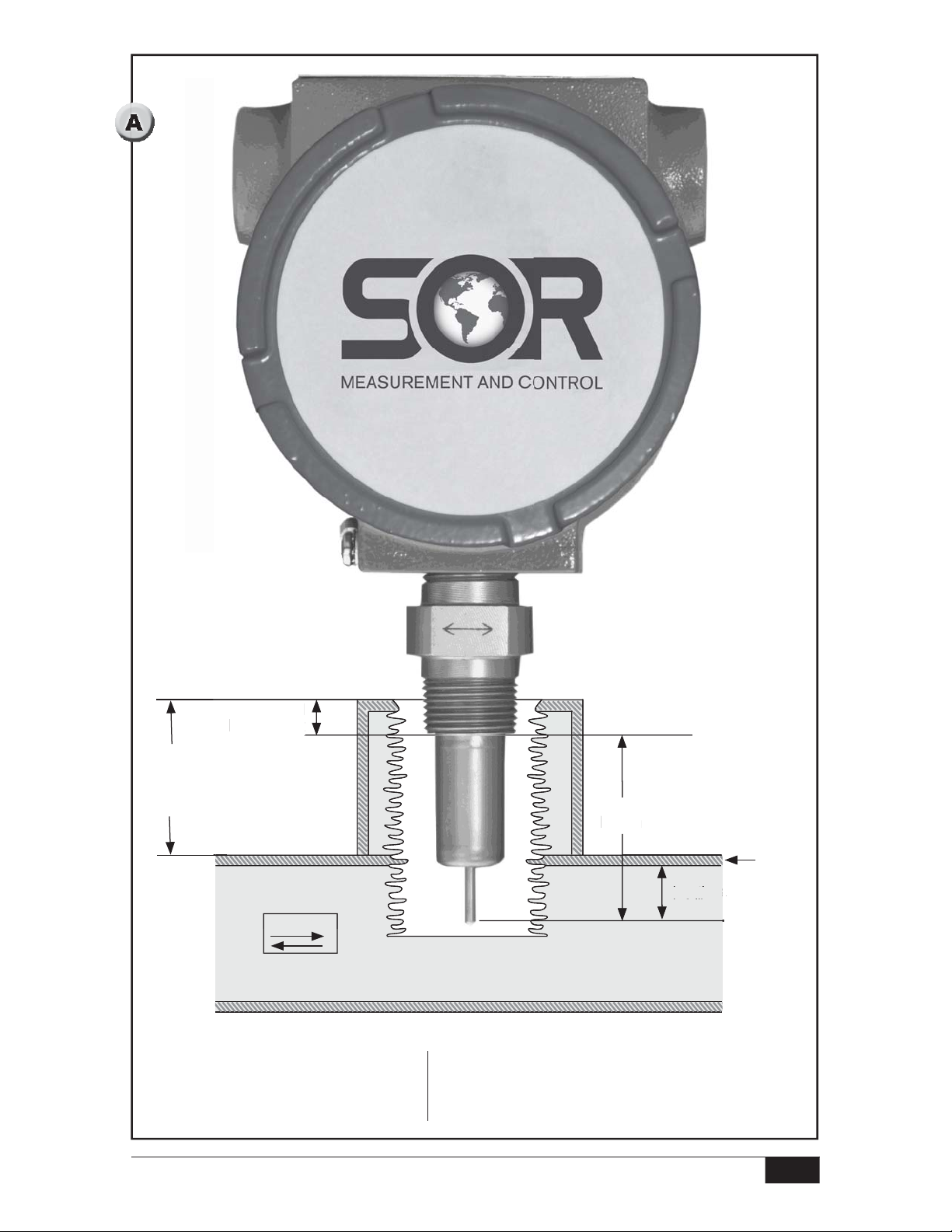
It is generally recommended that the sensor tips be located at 1/4 of the pipe’s
inside diameter (I.D.) assuming pipe is full. (See
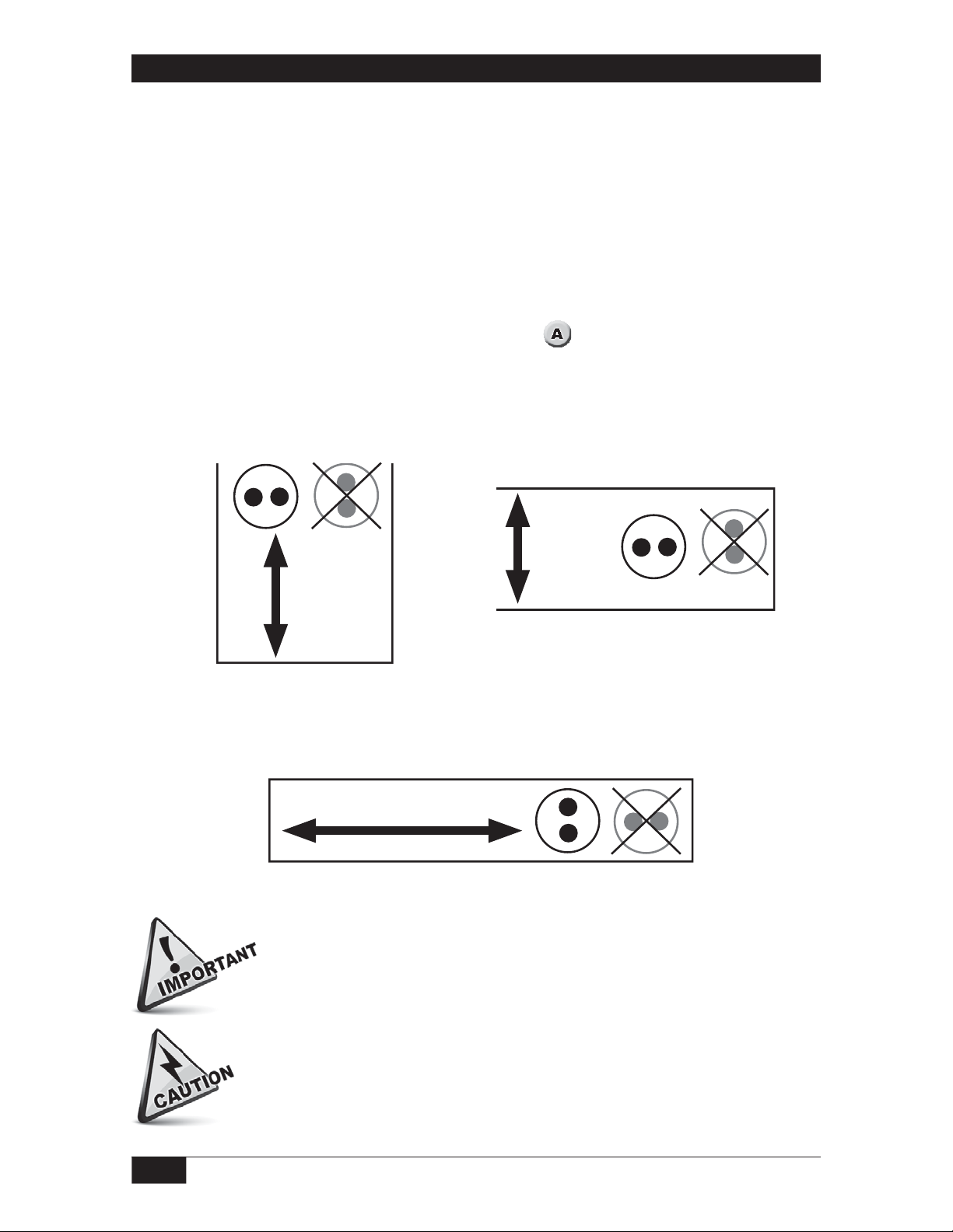
Level Application
The switch body MUST be oriented with the two sensor tips aligned paralled to the
level being detected. (Disregard for top mount installation.)
Sensor
Tips
Tips
Sensor
Incorrect
Material
Direction
)
Material
Direction
Sensor
Tips
Sensor
Incorrect
Tips
Flow Application
The swtich body MUST be oriented with the two sensor tips aligned perpendicular
to the flow being detected.
Material Direction
Sensor
For level and ow applications the material you are monitoring MUST contact the
two sensor tips at the same time .
Use a 1-1/8”, open-end wrench to tighten at the HEX ats of the MNPT of
a standard switch. Do not use the instrument head to tighten the switch
to the mounting port. Rotation of the instrument head with respect to the
sensor body may cause internal wiring damage.
Tips
Sensor
Tips
2/12
Form 1024 (08.13) ©SOR Inc.
Page 3
Pipe
h
p
pp
ll)
ead
t
Nozzle/
Coupling
Length
Thread
Thr
Engagement
ngagemen
Flow
*Sensor
ensor
Length
Lengt
Pipe Wall
Thickness
1/4 of pipe I.D. (preferred
/4 of pi
insertion assuming pipe
s fu
is full)
Unit can be mounted above or below pipe. Mounting on top of pipe is displayed above.
Nozzle/Coupling length
*Sensor Length =
+ Pipe wall thickness
+ 25% of pipe I.D.
- Thread engagement
Form 1024 (08.13) ©SOR Inc.
3/12
Page 4
Electrical Installation
Remove the instrument enclosure lid by unscrewing in a counterclockwise direction.
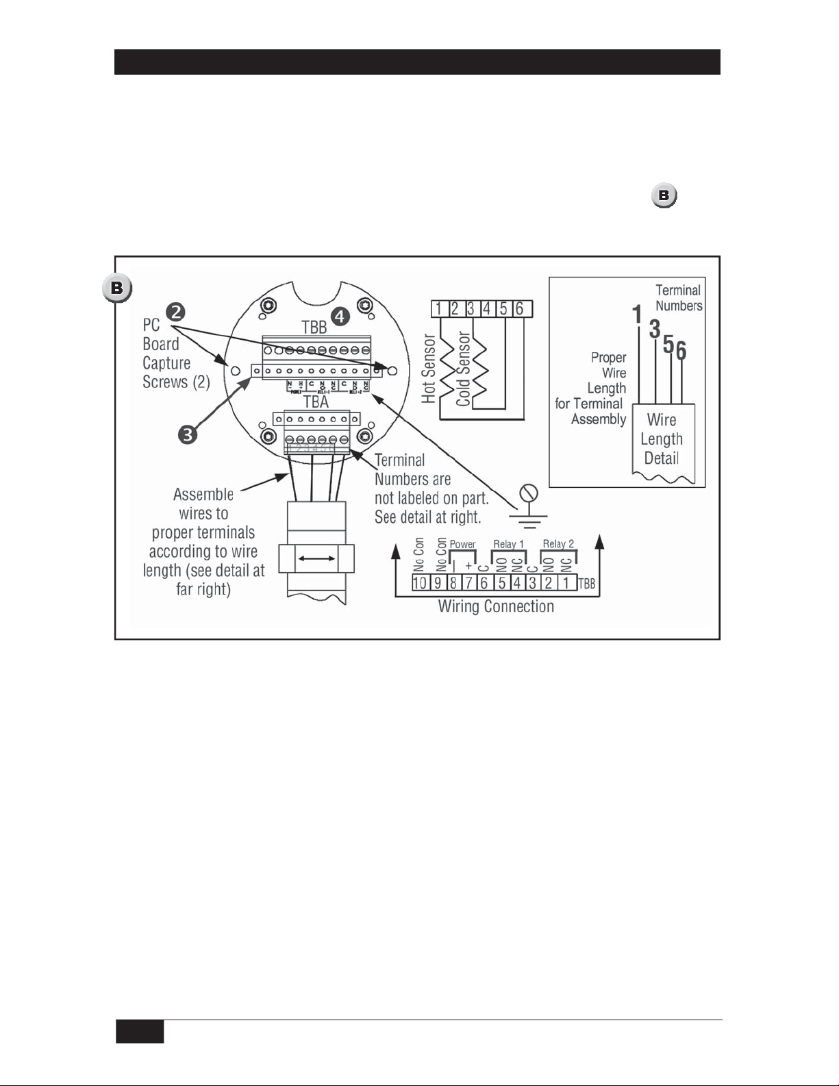
Loosen the two, board-retaining captured screws.
Remove the printed circuit board by grasping the transformer on the center of the
board and, while rocking gently back and forth, pull firmly outward.
Connect power and alarm relay wiring to Terminal Block TBB as shown in
Reinstall the switch electronics and tighten the retention screws.
.
NOTE: Connections to sensors are factory installed and should not be disconnected in the eld.
NOTE:
TBB8. For 115 VAC or 230 VAC operation, there is no polarity.
NOTE: Connect ground wire to the ground screw located in back of instrument enclosure. A
ground wire must be attached to the ground screw located inside and on the back of
instrument head for proper operation.
For 24 VDC operation (factory prepared), connect +24 VDC to TBB7 and 24 VDC return to
4/12
Form 1024 (08.13) ©SOR Inc.
Page 5

Setup and Operation
Remove the instrument head cover. Turn counterclockwise to expose the electronics.
Turn on power at its source.
Observe that either the red or green LED illuminates.
If neither lamp illuminates, refer to the troubleshootIng section.
L.E.D. and Relay Status Logic (Fail-Safe)
The L.E.D.s (L1-Red and L2-Green) are an indication of the sensor status (dry or wet) and
are not affected by the position of the fail-safe jumper J-2. The fail-safe jumper J-2 changes
the relay activation status allowing the user to select the fail-safe, power-off condition most
appropriate to the application. Refer to
sensors, L.E.D. lights, relay coil and contacts for each position of the fail-safe jumper J-2.
Pre-Operational Check
If the switch is installed and product level is below sensor level, or there is no flow,
the following procedure to verify preliminary operation.
Normal Operation (as set at the factory) The switch comes configured from the factory with the
following operation with the J-2 jumper in the B position. (See
Level Sensor Status
Dry or Lower Therm. Differential Fluid
(i.e. hydrocarbons)
Wet or Higher Therm. Differential Fluid (i.e. water)
Alternate Operation (Field Selectable) The relay logic may be reversed by moving the J-2 jumper to position A.
(See
, page 7)
Level Sensor Status
Dry or Lower Therm. Differential Fluid (i.e. hydrocarbons)
Wet or Higher Therm. Differential Fluid (i.e. water)
and , showing the logic conditions between the
use
, page 7)
L1
Red LED
ON OFF Energized
OFF ON
L1
Red LED
ON OFF
OFF ON Energized
L2
Green LED
L2
Green LED
Relay Coil
Status
De-energized
Relay Coil
Status
De-energized
Relay Contact Status
oNC
oNO
oNC
oNO
Relay Contact Status
oNC
oNO
oNC
oNO
Normal Operation (as set at the factory) The switch comes configured from the factory with the
L1
L1
, page 9)
L2 Green
LED
L2 Green
LED
Relay Coil
Status
De-energized
Relay Coil
Status
De-energized
following operation with the J-2 jumper in the B position. (See
Flow Sensor Status
No flow or flow below set point ON OFF Energized
Flow or flow above set point OFF ON
Alternate Operation (Field Selectable) The relay logic may be reversed by moving the J-2 jumper
to position A. (See
, page 9)
Flow Sensor Status
No flow or flow below set point ON OFF
Flow or flow above set point OFF ON Energized
Red LED
Red LED
Form 1024 (08.13) ©SOR Inc.
Relay
Contact Status
oNC
oNO
oNC
oNO
Relay
Contact Status
oNC
oNO
oNC
oNO
5/12
Page 6

Calibration for Level Switches
For optimum operation, calibration must be accomplished at actual process
temperature and pressure conditions. Using
system as follows:
as a location guide, adjust the
Remove the instrument enclosure lid by turning it counterclockwise.
Apply power to the T21. Allow 5 minutes for the T21 to warm up. Verify J1 jumper is in
the level position (Factory Default).
Ensure that the tank liquid level is below the probe sensor tips and the tips are dry.
Set the trip adjust potentiometer to zero fully counterclockwise (ccw).
Adjust the dry adjust pot so that the red LED just illuminates. This is a 25-turn
pot. If the green LED is on, turn the pot counterclockwise (ccw). If Red LED is on,
turn the pot clockwise (cw).
Toggle the dry adjust pot back and forth until the switching point is well defined.
Leave the red LED illuminated. To ensure best definition/performance, wait
approximately 30 seconds between toggles.
Raise the level of the liquid to be detected until the probe/sensor tips are submerged
and wet (covered).
Set the trip adjust pot to 100 (fully clockwise).
Adjust the wet adjust pot so that the green LED just does illuminate. This is a
25-turn pot. If the green LED is on, turn the pot clockwise. If the red LED is on,
turn the pot counterclockwise
Toggle the set adjust pot back and forth until the switching point is well defined.
Leave the green LED illuminated. To ensure best definition/performance, wait
approximately 30 seconds between toggles.
Adjust the trip adjust pot to 80 and the calibration is complete.
6/12
Form 1024 (08.13) ©SOR Inc.
Page 7

Fuse
F1
PC Board
Retention
Screw (2)
L1 Red “ON” for Dry/No Flow
J2
L2 Green “ON” for Wet/
Full Flow
100
Wet
Trip
Adjust
Dry
0
J1
J1
J2
Low Flow
Form 1024 (08.13) ©SOR Inc.
High Flow/Level
Position
B
Postion
A
7/12
Page 8

Calibration for Flow Switches
Using as a location guide, adjust the system as follows:
Remove instrument enclosure lid by turning it counterclockwise.
Apply power to the T21. Allow 5-minute warm-up. Verify J1 jumper is in low flow setting if
air/gas flow rate is approximately 20 f/s and below (factory default). For liquid or high air/gas
flow rates, the jumper should be in high flow/level position.
Ensure that the pipeline is filled with fluid and at no or minimum flow.
Set trip adjust potentiometer to zero fully counterclockwise (ccw).
Adjust the no-flow pot so that red LED just illuminates. This is a 25-turn pot. If green LED is
on, turn pot counterclockwise (ccw). If the red LED is on, turn the pot clockwise (cw).
Toggle no-flow pot back and forth until the switching point is well defined. Leave red LED illumi-
To ensure best definition/performance, wait approximately 30 seconds between
nated.
toggles.
Adjust liquid or gas flow to maximum velocity. Ensure that flow is homogenous, constant
and free of bubbles if a liquid.
Set trip adjust pot to 100 (fully clockwise).
Adjust the full-flow pot so the green LED just illuminates. This is a 25-turn pot. If green LED
is on, turn pot clockwise. If red LED is on, turn the pot counterclockwise.
Toggle full-flow pot back and forth until switching point is well defined. Leave green LED illuminated.
To ensure best definition/performance, wait approximately 30 seconds between toggles.
If the switch is to be used for flow - no flow, set the trip adjust pot to 50 and go to step 14.
A more exact flow rate setting may be achieved by establishing flow at a desired rate with a
separate flow meter and proceeding to step 13, to establish trip point.
Adjust the trip adjust pot to obtain a trip as exhibited by a LED illumination. If a trip on
decreasing flow is desired, set for red LED illumination. If a trip on increasing flow is
desired, set for green LED illumination.
Verify the switch will reset by returning actual product flow to maximum or minimum flow rates.
NOTE: This adjustment may be done for tripping points between 10% and 90% of the span from
no ow to max ow.
8/12
Form 1024 (08.13) ©SOR Inc.
Page 9

Fuse
F1
PC Board
Retention
Screw (2)
L1 Red “ON” for Dry/No Flow L2 Green “ON” for Wet/
J2
Full Flow
Span
Trip
Adjust
Zero
100
0
Low Flow
Position
B
J1
Postion
A
J2
J1
High Flow/Level
NOTE: For use as Flow Switch
1. Insertion Length should be
approximately 1/4 Pipe I.D.
2. The unit should be installed on a
straight pipe run with at least 10
pipe diameters upstream and 5
pipe diameters downstream.
Form 1024 (08.13) ©SOR Inc.
9/12
Page 10

Dimensions
30.2
1.19
110.4
4.34
1.6
0.06
28.6 ACROSS FLATS
1.13
B
131.8
5.19
A
1
1
GROUND
SENSOR LENGTH ± 1/8
PER SALES ORDER
SCREW
34.8
1.37
63.5
2.50
127.0
5.00
PROCESS
CONNECTION
SEE TABLE
2X ELECTRICAL
CONNECTION
SEE TABLE
Dimensions are for reference only.
for a particular model number.
Linear = mm/inches
Drawing 0390596
10/12
Contact the factory
for certified drawings
DIMENSION APPROXIMATE AND BASED
1
ON A FIVE THREAD ENGAGEMENT
PROCESS
CONNECTION
1/2 NPTM
3/4 NPTM
1 NPTM
1-1/2 NPTM
2 NPTM
1 BSPTM
A
172.5
6.79
156.0
6.14
175.0
6.89
173.7
6.84
178.8
7.04
156.0
6.14
Form 1024 (08.13) ©SOR Inc.
14.3
0.56
19.1
0.75
19.1
0.75
19.1
0.75
19.1
0.75
19.1
0.75
B
Page 11

Cleaning
The probe may be cleaned by soaking, spraying solvents or detergent and water onto
the sensor tubes, or by ultrasonic cleaning.
Lime deposits can be safely removed by soaking in 20% hydrochloric acid. Warming
to 150°F is permissible to speed this process.
For unusual cleaning problems, contact the SOR factory to determine the exact materials
of construction and chemical compatibility before using strong acids or unusual
cleansers. Do not sandblast or scour the sensing probes with abrasive cleaners.
The sensing probes could be damaged by abrasives.
Troubleshooting
General Information
Each unit is different. Settings may not be identical from unit to unit
Moving the trip adjust pot closer to 100 produces
- Slower “On” response
- Faster “Off” response
Set span at maximum possible flow rate (as far above the span setting as possible)
Once again, the catalog J1 jumper settings are a starting point only
What do I do if...
... my zero or span is shi ting during calibration?
The probes have likely not warmed up sufficiently. Apply power, place the probes in
the zero state process, and wait for 5 minutes. (In dry air, the heated probe may be
too hot to touch.)
... my setpoint has shifted shortly after calibration?
The probes were likely not allowed to warm sufficiently during calibration. Apply
power, place the probes in the zero state process, wait for 5 minutes, and repeat the
calibration process. In dry air, the heated probe should be hot to the touch.
... I cannot get the red light to illuminate when turning the zero pot?
• Make certain the heated probe is heating properly.
• Make certain the Trip Adjust pot is in the fully counter-clockwise position
• Change J1 jumper position and try again
• If calibrating for liquid flow, try performing the zero function in dry air
• Reverse Hot and Cold sensor wires and retry
... wire is the proper length for terminal assembly?
• Reverse the wires: 1 and 3
... I cannot get the green light to illuminate when turning the span pot?
• Make certain the heated probe is heating properly.
• Make certain the Trip Adjust pot is in the fully counter-clockwise position
• Change J1 jumper position and try again
• If calibrating for liquid flow, try performing the zero function in dry air
• Reverse Hot and Cold sensor wires and retry
Form 1024 (08.13) ©SOR Inc.
11/12
Page 12

• Turn the unit around so that the other side of the probes faces the flow
- RTD’s have a front and a back. Sometimes turning the probes around so that
the other side is facing the flow will produce better results
... the unit calibrated well but at some later point my setpoint has shifted?
• Make sure the process has not changed
• Changes in the thermal properties of the fluid will affect set point accuracy
• Check the probe tips for uneven build-up
- If the build up on one probe (usually the hot) is much greater than the other
then the thermal differential relationship is compromised.
• Check inside of pipe for build-up
- If the process sticks and builds-up on the inside of the pipe, the diameter can
get smaller causing a change in process velocity.
• If all else fails, check the integrity of the sensor and boards (for step-by-step
instructions see the Thermal Differential Point Switch_1024 General Instruction
Manual on sorinc.com)
Power and Continuity Veri cation
Turn the power off to the T21 Switch.
Remove the instrument enclosure cover.
Loosen the PC board capture screws. (See , page 4)
Unplug the PC board from the instrument enclosure by pulling straight out on the transformer.
Reapply power and verify correct voltage at pins 7 (positive for DC) and 8 (negative for
DC) of TBB. (See
If voltage is correct, verify the fuse (F1) on the PC board is not blown. (See , page 9)
If fuse is not blown, proceed to Sensor/Electronics Functionality verification step 2.
If fuse is blown, replace with the appropriate fuse.
Sensor/Electronics Functionality Veri cation
Turn the power off to T21 Switch.
Allow a 5-minute cool down.
Measure the resistance of each RTD at pins 1 and 6 of TBA (See , page 4) for the
first RTD, and pins 3 and 5 of TBA for the second RTD. These resistances should
be 110 ± 10 ohms (with sensors at approximately 70°F) and within 5% of each other
in value.
Measure the insulation resistance between pin 1 of TBA and the case of the Switch. It
should be greater than 20 megohms.
If the switch sensor assembly resistances are not as specified above, the switch sensor
assembly must be replaced.
, page 4)
If the switch sensor assembly resistances are as specified, the switch PC board
must be replaced.
Printed in USA sorinc.com
14685 West 105th Street, Lenexa, KS 66215 913-888-2630 800-676-6794 USA Fax 913-888-0767
12/12
Registered Quality System to ISO 9001
Form 1024 (08.13) ©SOR Inc.
 Loading...