


131/141 Nuclear-Qualified
Differential Pressure Switches
General Instructions
131 |
Cover Screws |
Housing |
Wire Leads |
1/8” NPT(F) Vent Connection |
|
3/4” NPT(F) Conduit Connection |
|
|
Sensor |
Body |
|
Mounting Holes |
|
|
|
|
|
|
High Side Process Connection |
Low Side Process Connection |
|
141 |
Cover Screws |
Housing |
Wire Leads |
1/8” NPT(F) Vent Connection |
3/4” NPT(F) Conduit Connection |
||||
Body |
Sensor |
||||
|
|||||
|
|
|
|
|
Mounting Holes |
|
|
|
|
|
|
Low Side Process Connection |
Low Side Process Connection |
||||
|
|
|
|
||
High Side Process Connection |
|
||||
NOTE: If you suspect that a product is defective, contact the factory or the SOR® Representative in your area for a return authorization number (RMA). This product should only be installed by trained and competent personnel.
Installation
Mount pressure switch to rigid vertical mounting surface with four 1/4-20 Grade 5 screws (not supplied). Torque screws to 70 - 85 in/lbs. The 141 must be oriented with the sensor down (housing up).
Design and specifications are subject to change without notice.
For latest revision, go to www.sorinc.com
Form 1307 (04.13) ©SOR Inc. |
1/4 |
Process Connection
Be certain the process connection is tightened and positioned so bending and torsional forces imposed on pressure switch are minimal. Use care not to loosen sensor assembly from housing.
131 - One process connection is provided for the high-pressure side of the device and one for the low-pressure side.
141 - Two process connections are provided for the high-pressure side of the device and two for the low-pressure side. On liquid service, the extra process connections should be used to assist in bleeding the air out of the sensor. On gas service, they may be used to drain condensate or accumulated liquid.
When the process could be considered dirty in terms of suspended particles, it is recommended that 20-micron in-line filters be installed on the Hi and Lo pressure ports.
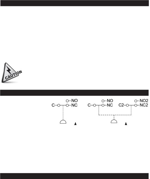
Electrical Connection
Electrical connections are |
|
|
|
|
|
|
|
marked on the insulation |
|
|
|
|
|
|
|
of the wire leads. Conduit |
|
|
|
|
|
|
|
should be installed without |
|
|
|
|
|
|
|
applying strain to the |
|
|
|
|
|
|
|
housing. |
Differential |
|
|
Differential |
|
|
|
|
Pressure |
|
|
Pressure |
|
|
|
|
|
|
|||||
|
|
|
|
|
|
|
|
Minimum Bend Radius for Wire |
|
|
|
||||
Permanent Training |
|
|
|
|
1/2”R |
||
|
|
|
|
|
|
|
|
Pulling Tension |
|
|
|
|
1”R |
||
|
|
|
|
|
|
|
|
Terminating Junction |
|
|
|
1/4”R |
|||
|
|
|
|
|
|
|
|
Site Storage
Store switch in a dry area in the original shipping package. Shelf life is 10 years for a maximum ambient temperature of 80°F, based on aging data in SOR Test Report 9058-102.
2/4 |
Form 1307 (04.13) ©SOR Inc. |
 Loading...