

Page 1
Nuclear Qualified
thermal system.
y
Temperature Switches
General Instructions
The SOR® temperature switch utilizes a SAMA Class II thermal system.
NOTE: This type of system requires that the entire
length of the sensing bulb be exposed to the
temperature being measured.
II
Recommended Measurement Procedure
In considering the validity of a measurement,
remember that temperature-sensing devices respond
only to the temperature that they experience. It may
be considerably different from the temperature one
is attempting to measure if the sensor is of improper
size or configuration, or if the sensor is not adequately
coupled thermally to the media whose temperature is
being measured. The calibration procedures given below
will assure accurate and repeatable measurement of the
set points of SOR temperature switches. If the switch is
normally mounted in a thermowell, consideration should
be given to the effect this may have on the accuracy of
the switch. It is recommended that a heat transfer paste
or oil be used to thermally couple the sensing bulb to the
thermowell, both in service and during testing.
ond
a
e
per
ately
re is
n below
of the
itch is
should
cy of
r paste
lb to the
NOTE: If you suspect that a product is defective, contact the factory or the SOR Representative
in your area for a return authorization number (RMA). This product should only be installed by
trained and competent personnel.
Table of Contents
Design and
specifications are
subject to change
without notice.
For latest revision, go to
www.sorinc.com
Form 655 (04.13) ©SOR Inc.
Recommended Measurement Procedure ...1
N6 Housing ......................................3
TA Housing .......................................4
RT Housing ......................................5
Installation .......................................6
Site Storage .....................................6
Electrical Connection ...........................6
Calibration .......................................7
1/8
Page 2

Recommended temperature measurement procedure for switches used to sense
temperatures of liquids and steam with set points below 200°F:
Use a liquid bath (ethylene glycol, water, oil, etc.) with sufficient circulation to provide a
uniform bath temperature and efficient transfer of heat from the liquid to the sensing bulb.
Fully submerge the sensing bulb into the bath. Direct-mount sensing bulbs should be
submerged up to the bottom of the process connection threads.
Locate the tip of the temperature measuring standard (thermocouple, RTD, etc.) at the
mid point of, and adjacent to the sensing bulb.
Locate the sensing bulb and temperature measuring standard so that they do not touch
the sides or bottom of the bath or the heating and cooling coils.
When the bath temperature is within 3°F of the set points, it is recommended that the
temperature of the bath be changed at a rate of 0.1°F per 5 seconds or slower.
The minimum and maximum bath temperatures that the switch sees during testing
should be duplicated each time the switch is tested. It is recommended that the temperature of the bath be changed from the normal operating temperature to the critical
set point and back to the reset. Do not overshoot the critical set point if the switch is
going to be cycled more than once during the test.
Recommended temperature measurement procedures for switches used to sense temperatures of liquids and steam with set points above 200°F:
Recommended procedures for set points above 200°F are identical to those for set points
below 200°F with the exception of the bath used to test the switches. We recommend
either a circulated oil bath or a fluidized sand bath. The bath should be tested for uniformity
of temperature from top to bottom and side to side. If necessary, steps may be taken to
improve the uniformity of temperature, such as altering the air flow through a sand bath or
improving circulation or stirring.
Recommended temperature measurement procedures for switches used to sense air
or gas temperature:
Switches used to measure the temperature of air or gas should be tested in such a way that
it simulates the actual service conditions as closely as possible. Chances of measurement
error are much greater in air because of its poor thermal conductivity. Rate of change of
temperature, velocity of air flow, location of sensing bulb, and location of standard must
be duplicated as closely as possible for successive calibration checks to assure repeatable results. If the switch is being used as a room thermostat, the entire switch should be
placed in a test oven for calibration and testing. If only the sensing bulb is exposed to the
air or gas being measured, then only the sensing bulb should be inserted into the oven or
test apparatus for calibration and testing. In this case the switch housing should be kept at
room temperature.
2/8
Form 655 (04.13) ©SOR Inc.
Page 3
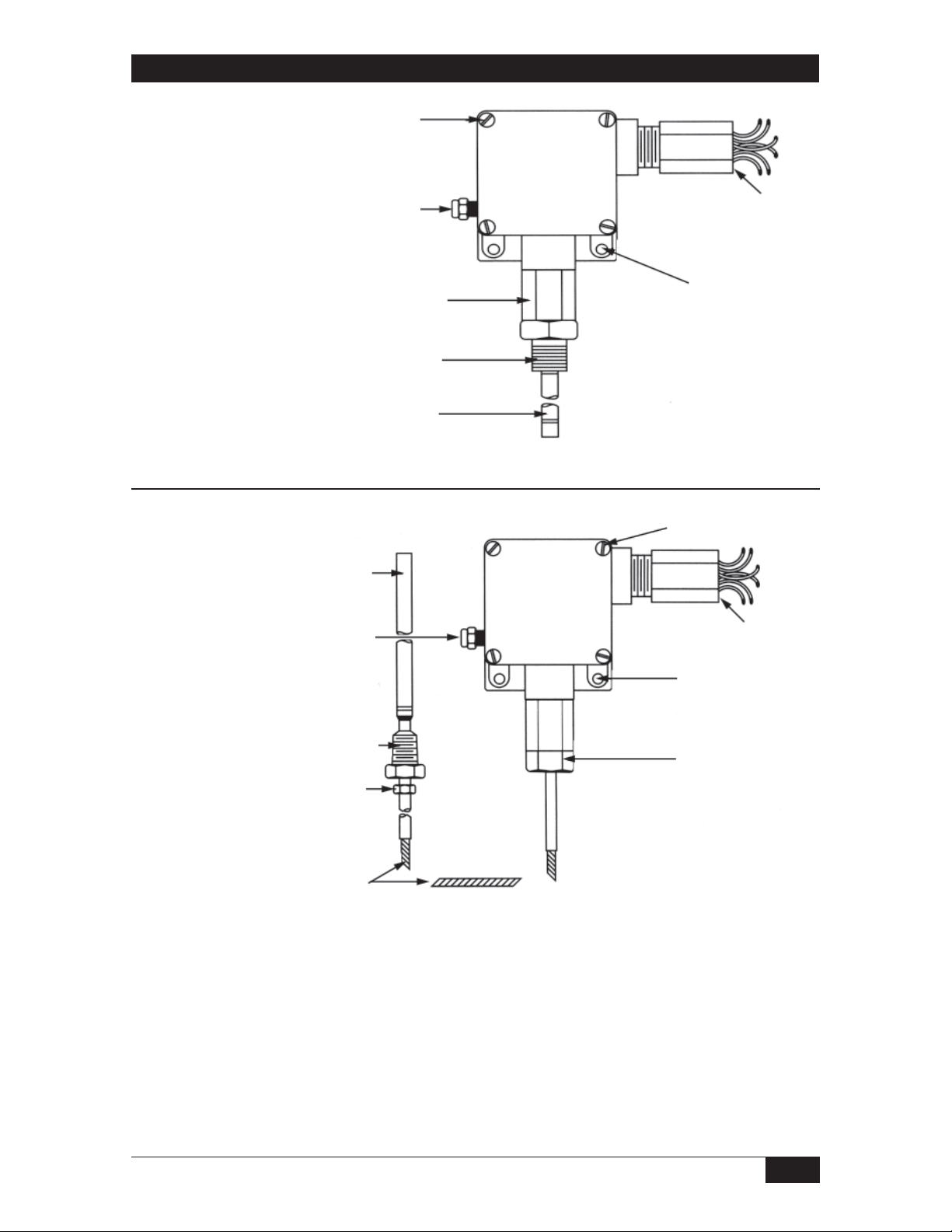
N6 Housing
Direct Mount
Remote Mount
Cover
Screws
1/8” NPT(F)
Vent
Connection
Body
Process
Connection
Sensing Bulb
3/4” NPT(F)
Conduit Connection
Mounting
Holes
Cover Screws
Sensing
Bulb
1/8” NPT(F)
Vent
Connection
Process
Connection
Gland
Nut
Capillary
Conduit Connection
3/4” NPT(F)
Mounting
Holes
Retainer
Mounting Hardware Fasteners per SOR Test Report 9058-102 consist of two 1/4-20,
Grade 5 screws (not supplied). Torque screws to 70 to 85 in-lbs.
Maintenance Replace cover gasket (SOR P/N 8923-180) whenever cover is removed or
minimum of once every 5 years, whichever comes first. Remove the four cover screws.
Remove the old gasket. Place new gasket between housing and cover. Line up holes in
cover, gasket and housing. Insert the 4 screws and torque each to 7 to 10 in-lbs.
Form 655 (04.13) ©SOR Inc.
3/8
Page 4

TA Housing
Direct Mount
Remote Mount
Cover
1/4” NPT(F)
Vent Connection
Body
Process Connection
Sensing Bulb
U-Bolts
3/4” NPT(F)
Conduit
Connection
Cover
Sensing
Bulb
Process
Connection
Gland Nut
Capillary
1/4” NPT(F)
Vent
Connection
U-Bolts
3/4” NPT(F)
Conduit Connection
Retainer
Mounting Hardware Fasteners per SOR Test Report 9058-102 consist of three standardgrade 1/4-inch U bolts (not supplied).
Maintenance Replace cover o-rings (SOR P/N 8923-206 and 8923-207) whenever cover
is removed or minimum of once every 5 years, whichever comes first. Unscrew the cover.
Remove the old o-rings. Place new o-rings in grooves of cover. Lubricate o-rings with
light film of Krytox 240AC grease (or equivalent fluorinated grease). Tighten cover until the
flange of the cover makes contact with the housing.
4/8
Form 655 (04.13) ©SOR Inc.
Page 5

RT Housing
Direct Mount
Remote Mount
1/8” NPT(F)
Vent
Connection
Cover
Screws
Body
Process Connection
Sensing Bulb
Sensing
Bulb
3/4” NPT(F)
Conduit
Connection
Mounting Holes
Cover Screws
3/4” NPT(F)
Conduit Connection
1/8” NPT(F)
Vent
Connection
Process
Connection
Gland
Nut
Capillary
Mounting
Holes
Retainer
Mounting Hardware Fasteners per SOR Test Report 9058-102 consist of two 1/4-20,
Grade 5 screws (not supplied). Torque screws to 70 to 85 in-lbs.
Maintenance Replace cover gasket (SOR P/N 8923-181) whenever cover is removed or
minimum of once every 5 years, whichever comes first. Remove the four cover screws.
Remove old gasket. Place new gasket between housing and cover. Line up holes in cover,
gasket and housing. Insert the 4 screws and torque each to 7 to 10 in-lbs.
Form 655 (04.13) ©SOR Inc.
5/8
Page 6

Installation
Refer to applicable drawing for mounting dimensions of specific model number. The
vent connection must be plugged or vented to dry atmosphere as required by application
requirements.
Direct Mount Line mount or mount to a rigid mounting surface with process connection
down (6 o’clock). If the switch must be removed from a thermowell, loosen the process
connection by placing a 1-1/4” wrench on the hex adjacent to the process threads. Do not
use wrench on the sensing body. (See drawings.)
Remote Mount Mount to a rigid mounting surface with retainer down (6 o’clock). Secure
capillary every two feet. To install sensing bulb, loosen gland nut so that the process connection turns freely. Re-tighten gland nut after process connection is installed.
Site Storage
Store switch in a dry area in the original shipping package. Shelf life is 10 years for a
maximum ambient temperature of 80°F, based on aging data in SOR Test Report 9058-102.
Electrical Connection
Electrical connections are marked on the insulation of the wire leads. Conduit should be
installed without applying strain to the housing.
Temperature Temperature
Minimum Bend Radius for Wire
Permanent Training 1/2” R
Pulling Tension 1” R
Terminating Junction 1/4” R
6/8
Form 655 (04.13) ©SOR Inc.
Page 7

Calibration
To adjust temperature at which switch will operate, remove cover and tighten the hex head
adjusting nut with a 3/4-inch wrench to increase temperature; loosen to reduce temperature.
Sighting across the top of the 3/4-inch hex adjusting nut to the scale gives approximate
set point temperature. Use accurate test gear external to the temperature switch to set or
check set points. See recommended measurement procedure on Page 1. After calibration
is complete, reinstall the cover with new gaskets or o-rings as required by the maintenance
instructions.
The switching element has been positioned with a dial indicator to a
tolerance of +/-.002 inches. Do not move this switching element! Its position
has nothing to do with the set point adjustment. Any movement can either
render the switch inoperative or cause the switching element to be damaged
with over-temperature.
Switching Element
Adjusting Nut
Form 655 (04.13) ©SOR Inc.
Calibration Scale
7/8
Page 8

Printed in USA www.sorinc.com
14685 West 105th Street, Lenexa, KS 66215 913-888-2630 800-676-6794 USA Fax 913-888-0767
8/8
Form 655 (04.13) ©SOR Inc.
 Loading...