

Page 1
Replacing the
Switch Mechanism
General Instructions
SOR® Level Controls are designed for easy replacement of the switch mechanism
without removing the control from the process. The following steps are recommended
for proper replacement.
Electrical power must be disconnected from explosion proof models before
the cover is removed. Failure to do so could result in severe personal injury
or substantial property damage.
Disconnect the external wiring at the terminal block, noting the position of each wire.
Mark the location of each switch mechanism on the enclosing tube. Loosen the
clamping screw closest to terminal block. Remove the switch mechanism(s) from
the enclosing tube.
Clamp each replacement switch mechanism on the enclosing tube according to the
marks from step 2. If applicable, interlock the lowest switch mechanism with the
baffle plate.
To avoid a signi cant calibration shift, each replacement switch mechanism
must be installed to match the position of the original switch mechanism on
the enclosing tube.
Actuate the switch mechanism. Check continuity to verify switch actuation.
Reconnect the external wiring to the terminal block.
Arrange the external wiring to avoid interference with the movement of the switch
mechanism or housing cover.
Replace the housing cover.
Each switch mechanism is factory adjusted for optimal actuation/
de-actuation. Do not adjust the switch mechanism without factory
instructions.
Ensure that wiring conforms to all applicable local and national electrical codes and
install unit(s) according to relevant national and local safety codes.
NOTE: If you suspect that a product is defective, contact the factory or the SOR Representative
in your area for a return authorization number (RMA). This product should only be installed by
trained and competent personnel.
Design and specifications are subject to change without notice.
Form 448 (05.13) ©SOR Inc.
For latest revision, go to sorinc.com
Registered Quality System to ISO 9001
1/4
Page 2
NOTE:
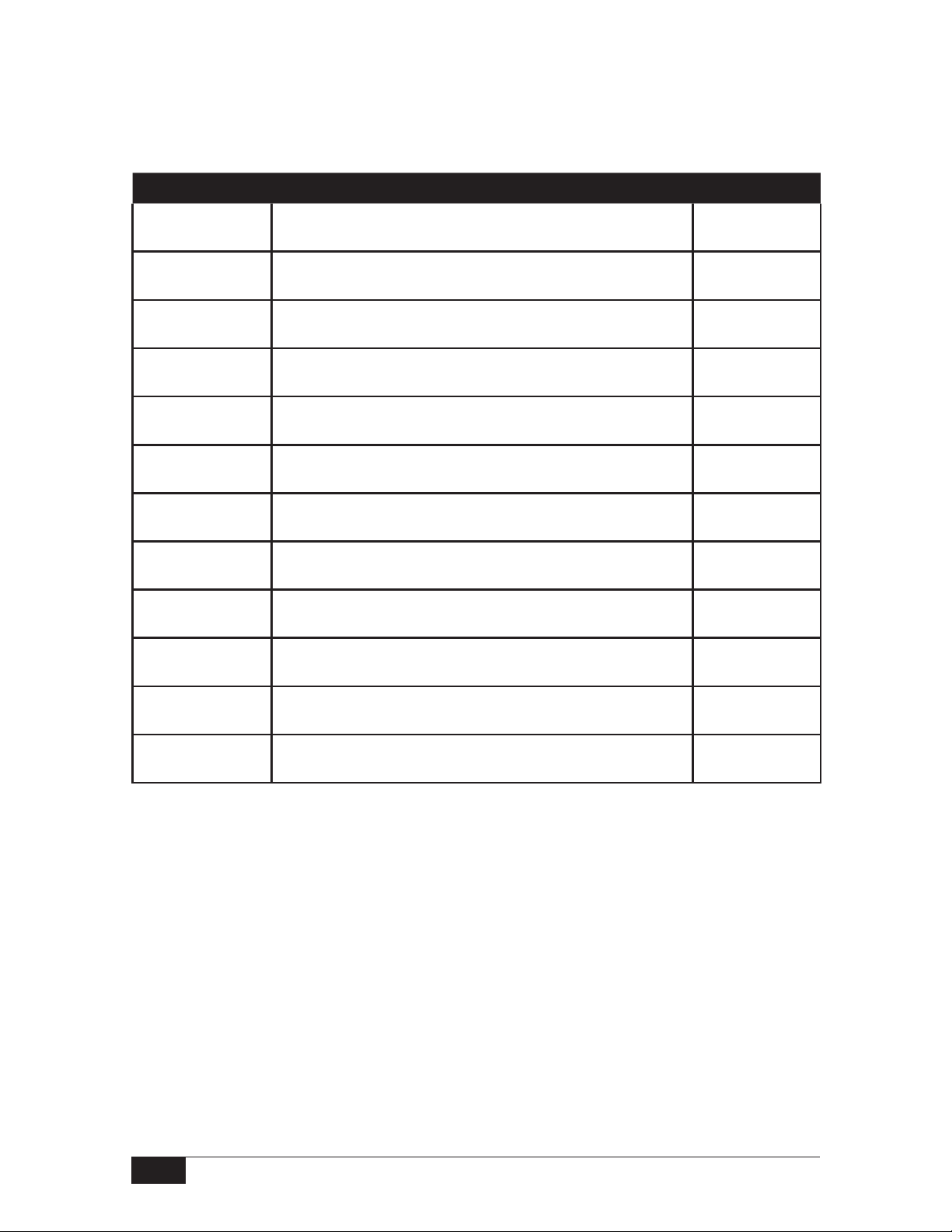
UL Listed or CSA, ATEX and SAA Certi ed Level Controls.
The original switch mechanism must be replaced with an identical switch mechanism.
Installation of a non-identical switching mechanism will void agency listing/certification.
Part No. Description
3160016 Dry Contact -SPDT Type A1
3160021 Dry Contact -DPDT Type A4
3160216 Dry Contact -SPDT (high-temperature) Type B1
3160221 Dry Contact -DPDT (high-temperature) Type B4
3160030 Dry Contact -SPDT (anti-vibration) Type D1
3160033 Dry Contact -DPDT (anti-vibration) Type D4
3160087 Dry Contact -SPDT (hermetically sealed) Type F1
3160093 Dry Contact -DPDT (hermetically sealed) Type F4
3160010 Dry Contact -SPDT (hermetically sealed) Type L1
3160015 Dry Contact -DPDT (hermetically sealed) Type L4
†3160307 Dry Contact -SPDT
†3160306 Dry Contact -DPDT
NOTE: DPDT mechanisms consist of two SPDT elements working in tandem.
(extra high-temperature)
(extra high-temperature)
Type Y1
Type Y4
† Type Y1 and Y4 switch mechanisms are not stackable.
E-Tube should be isolated from the process and brought to ambient temperature
before installing Y1 and Y4 type switches.
2/4
Form 448 (05.13) ©SOR Inc.
Page 3

Form 448 (05.13) ©SOR Inc.
3/4
Page 4

Printed in USA sorinc.com
14685 West 105th Street, Lenexa, KS 66215 913-888-2630 800-676-6794 USA Fax 913-888-0767
4/4
Registered Quality System to ISO 9001
Form 448 (05.13) ©SOR Inc.
 Loading...