

Page 1
These instructions provide information for
installation, process connection, electrical
connection and calibration of Nuclear Qualified
Pressure Switch with Terminal Block.
NOTE: If you suspect that a product is defective,
contact the factory or the SOR
your area for a return authorization number (RMA).
This product should only be installed by trained
and competent personnel.
®
Representative in
.
Installation
Nuclear Qualified
Pressure Switch
with Terminal Block
General Instructions
The vent connection must be plugged or vented to dry atmosphere as required by
application requirements. Test Data Sheet SOR form #716 is supplied for each serial
number and provides switch performance data in the vented and plugged condition.
Failure to mount the housing on a at mounting surface may result in
torsional forces on the housing that could cause false trips or render the
pressure switch inoperative.
Process Connection
Securely connect process line to pressure port using two wrenches: one to hold hex flats
on pressure port, the other to tighten process pipe or tube fitting.
Be certain the process connection is tightened and positioned so bending
and torsional forces imposed on pressure switch are minimal. Use care
not to loosen pressure port from body or body from housing.
Design and specifications are subject to change without notice.
Form 1472 (05.13) ©SOR Inc.
For latest revision, go to sorinc.com
1/4
Page 2
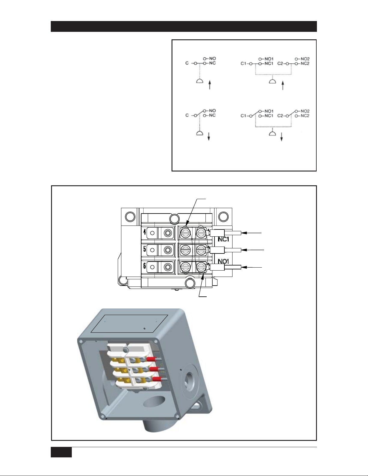
Electrical Connection
Conduit should be
installed without
applying strain to the
housing. Screw terminal
block is provided with
marked insulation as
denoted below. Tighten
screw terminals to
10 in-lbs. (1.1 N-m)
SPDT DPDT
Pressure
Vacuum
Pressure
Vacuum
Vacuum switches only
Drawing 9013747
INSTALL WIRING ON TOP ROW ONLY.
NC TERMINAL
C TERMINAL
NO TERMINAL
SOR INSTALLED WIRING, DO NOT REMOVE.
2/4
Form 1472 (05.13) ©SOR Inc.
Page 3

Site Storage
Store switch in a dry area in the original shipping package. Shelf life is 10 years for a
maximum ambient temperature of 80°F, based on aging data in SOR Test Report 9058-102.
Calibration
To check the set point of a switch, monitor either the common (C) and normally open (NO)
or the common (C) and normally closed (NC) contacts for change of state. Connect the
process connection to a regulated hydraulic or pneumatic pressure source. Monitor with
an accurate pressure measuring standard. Slowly increase or decrease the pressure to
accurately capture the precise moment that the switch changes state. To assure the most
accurate and repeatable results, the switch must be tested in an identical manner each time
the calibration is checked.
Increasing Set Points
If the normal operating pressure is below the
set point, then the pressure should be increased
from 0 PSI up to the increasing set point and
then back down to the reset point. Repeat this
cycle as necessary.
Switching Element
Decreasing Set Points
If the normal operating pressure is above
the set point, then the calibration should be
checked by first pressurizing to the normal
operating pressure, then reducing the pressure
to the decreasing set point, and then increasing
the pressure to the reset point. Repeat this cycle
as necessary.
To adjust pressure at which switch will operate, remove cover and tighten the hex head
adjusting nut with a 3/4” wrench to increase pressure; loosen to reduce pressure. Sighting
across the top of the 3/4-inch hex adjusting nut to the scale gives approximate set point
pressure.
After calibration is complete, reinstall the cover with new gaskets or o-rings as required by
the Maintenance instructions.
The Switching element has been positioned with a dial indicator to a
tolerance of
nothing to do with the set point adjustment. Any movement can either render
the switch inoperative or cause the switching element to be damaged with
overpressure.
±.002 inches. Do not move this switching element! Its position has
Adjusting Nut
Calibration Scale
Form 1472 (05.13) ©SOR Inc.
3/4
Page 4

RT Housing
Mounting Hardware
Cover Screws
Fasteners per SOR Test
Report 9058-102 consist of
two 1/4-20, Grade 5 screws
(not supplied). Torque screws
1/8 NPT(F)
Vent Connection
Conduit
Connection
to 70 to 85 in-lbs.
(7.9-9.6 N-m)
Maintenance
Body
Replace cover gasket (SOR
P/N 8923-181) whenever
cover is removed or minimum
Process Connection
(Pressure Port)
Mounting Holes
of once every 5 years,
whichever comes first. Remove the four cover screws. Remove old gasket. Place new
gasket between housing and cover. Line up holes in cover, gasket and housing. Insert the
4 screws and torque each to 7 to 10 in-lbs. (0.8-1.1 N-m)
Printed in USA sorinc.com
14685 West 105th Street, Lenexa, KS 66215 913-888-2630 800-676-6794 USA Fax 913-888-0767
4/4
Form 1472 (05.13) ©SOR Inc.
 Loading...