

Page 1

SORtrax Level Transmitter
General Instructions
SORtrax is a 4-20 mA continuous level transmitter. It produces a
4-20mA current superimposed on the 12-55 VDC loop supply lines. The
4-20mA current is proportional to the level sensed by the instrument.
SORtrax detects level based on process admittance. Bench or field
calibration is easily accomplished. Coarse and fine adjustments are
provided to allow the user full control over the zero and span settings,
and to insure the most accurate operation possible. Recalibration is
needed each time the content of the process changes, due to the
different dielectric constant of each material.
NOTE: If you suspect that a product is defective, contact the factory or the
®
Representative in your area for a return authorization number (RMA).
SOR
This product should only be installed by trained and competent personnel.
670K9
Probe Installation
Probes are mounted vertically from the top of a vessel. The probe must
be electrically isolated from the vessel; make no connection between the
probe and the vessel other than the process connection and (if applicable) the threaded
weight at the probe tip.
Do not weld any part of this instrument.
Make sure that the sensor can be fully inserted and tightened without interference from
obstructions inside the tank or vessel. The probe should be mounted away from inlet
fill paths. Spray from a fill path may cause false level indications.
Table of Contents
Probe Installation ...............................1
Design and
specifications are
subject to change
without notice.
For latest revision, go to
www.sorinc.com
Electrical Connection ...........................2
Empty and Fill Calibration .....................4
Bench Calibration ...............................5
Blind Calibration ................................6
Probe and Transmitter Performance Veri cation
..7
CE Mark Installation ............................7
RF Probe Grounding Scheme .................8
Control Drawings ...............................9
Troubleshooting ............................... 12
Dimensions .................................... 13
Form 837 (05.13) ©SOR Inc.
Registered Quality System to ISO 9001
1/16
Page 2

For pressurized vessels, seal the flanged or
threaded process connection to prevent leakage.
Do not use the sensor base as a handle to
tighten the process connection.
Use suitable mounting bolts to mount a flanged
probe on a flanged process connection.
Proper grounding is imperative for correct
operation of the unit.
Sensor
Base Hub
Apply thread
sealant
Apply wrench
to metal hex
or wrench
flats only!
Customer
Ground Lead
(optional)
Circuit Board
Ground Lead
SORtrax
Housing
Ground Screw
Open Sump or Basin
Do not suspend the unit by rigid conduit
installed in the electrical hub. When installing
the unit over an open sump or basin, use a
suitable bracket to support the instrument.
Condensation build-up inside the electronics
housing may damage the sensitive circuitry.
To prevent the ingress of moisture, use drip
loops or conduit runs which slope down from
the enclosure. (See
)
The unit can be grounded two ways. If
the tank is metallic, grounding is provided
by the tank. If the tank is not metallic, or
does not adequately make contact with
the sensor, a separate ground wire must
be provided by the customer. Run ground
wiring through the conduit and into the
electronics housing. Attach the ground
wire per
Bracket
.
Electrical Connection
Ensure that wiring conforms to all applicable local and national electrical codes and install
unit(s) according to relevant national and local safety codes.
Electrical power must be disconnected from explosion proof models before
the cover is removed. Failure to do so could result in severe personal injury
or substantial property damage.
2/16
Form 837 (05.13) ©SOR Inc.
Page 3

This product must be installed with an explosion proof breather vent per
agency requirements and the Nationsl Electric Code - Article 501, Section F,
paragraph 3.
Use 18 - 22 AWG shielded twisted pair wire to make all signal and power connections.
Ensure that wiring conforms to all applicable local and national electrical codes and install
unit(s) according to relevant national and local safety codes.
Make sure the power source is
turned off.
Remove the housing cover.
Pull power and signal wire through
the conduit connection and into
the control housing.
Locate TB1 on the control board.
(See
) Terminals are labeled
Current Meter or Resistive
Load (optional)
+
+
-
DC Power
Supply
TB1 Loop Power
Terminal Block
+
Terminal
-
Terminal
Control
Board
“+” and “-”. Connect power leads
to the proper terminals.
Do not exceed the maximum loop resistance for the circuit. (See )
Use the following formula to determine the maximum loop resistance of your circuit:
R (ohms) = (input voltage - 12) ÷ 20.0 mA
Loop Resistance vs. Power Supply Voltage
2200
NOTE: Refer to the
individual device
speci cations of
user-supplied
equipment to
determine the
resistive load
(in ohms) and the
power requirements.
2100
2000
1900
1800
1700
1600
1500
1400
1300
1200
1100
1000
900
800
700
600
500
400
300
Maximum Loop Resistance (Ohms)
200
100
0
0 10 15 20 25 30 35 40 45 55
600 Ohms
at 24 VDC
1400 Ohms
at 40 VDC
1 Ohm
at 12 VDC
2150 Ohms
at 55 VDC
900 Ohms
at 30 VDC
-
Form 837 (05.13) ©SOR Inc.
Power Supply Voltage (Volts)
3/16
Page 4

Empty and FIll Calibration
Electrical power must be disconnected from explosion proof models before
the cover is removed. Failure to do so could result in severe personal injury
or substantial property damage.
Electrical power must be disconnected from explosion proof models before
the cover is removed. Failure to do so could result in severe personal injury
or substantial property damage.
Install and connect power to the unit per previous pages. Install a current meter to the
unit per
Turn both potentiometers
(fine adjustments for
ZERO and SPAN) fully
counterclockwise.
(See
Zero Adjustment (4 mA)
.
ZERO AND SPAN
ADJUSTMENTS
Fine
)
Coarse
ZERO
Coarse
Fine
SPAN
Close switch #1 on coarse adjustment switches for ZERO and SPAN. (See )
Open switches #2, #3, and #4 on both coarse adjustment switches per .
With the tank at 0%, view the reading on
the current meter. If the output is less
than 4 mA, turn the fine ZERO adjustment
clockwise until 4 mA is reached.
NOTE: Only one ZERO switch may be in the
closed position at any time.
If the output is greater than 4 mA, close the other switches one at a time (opening
Coarse
Adjustment
switch #1 in
the closed
position, other
switches open
the previous switch) until a reading less than 4 mA is attained. Turn the fine ZERO
adjustment clockwise until 4 mA is reached.
NOTE: If 4 mA cannot be obtained, see the troubleshooting chart on page 14.
Span Adjustment (20 mA)
Set the process to desired high level. (See )
Ensure SPAN coarse adjust switch #1 is in the closed position,
100%
with all other switches open.
Rotate the SPAN fine adjustment pot clockwise until the meter
indicates 20 mA. If a 20 mA reading cannot be obtained,
proceed to step 10.
Open SPAN switch #1 (coarse) and close SPAN switch #2.
Repeat step 9. If a 20 mA reading cannot be obtained, repeat
the procedure closing switch #3 or #4 until 20 mA is indicated.
4/16
Form 837 (05.13) ©SOR Inc.
0%
Page 5
Bench Calibration
Electrical power must be disconnected from explosion proof models before
the cover is removed. Failure to do so could result in severe personal injury
or substantial property damage.
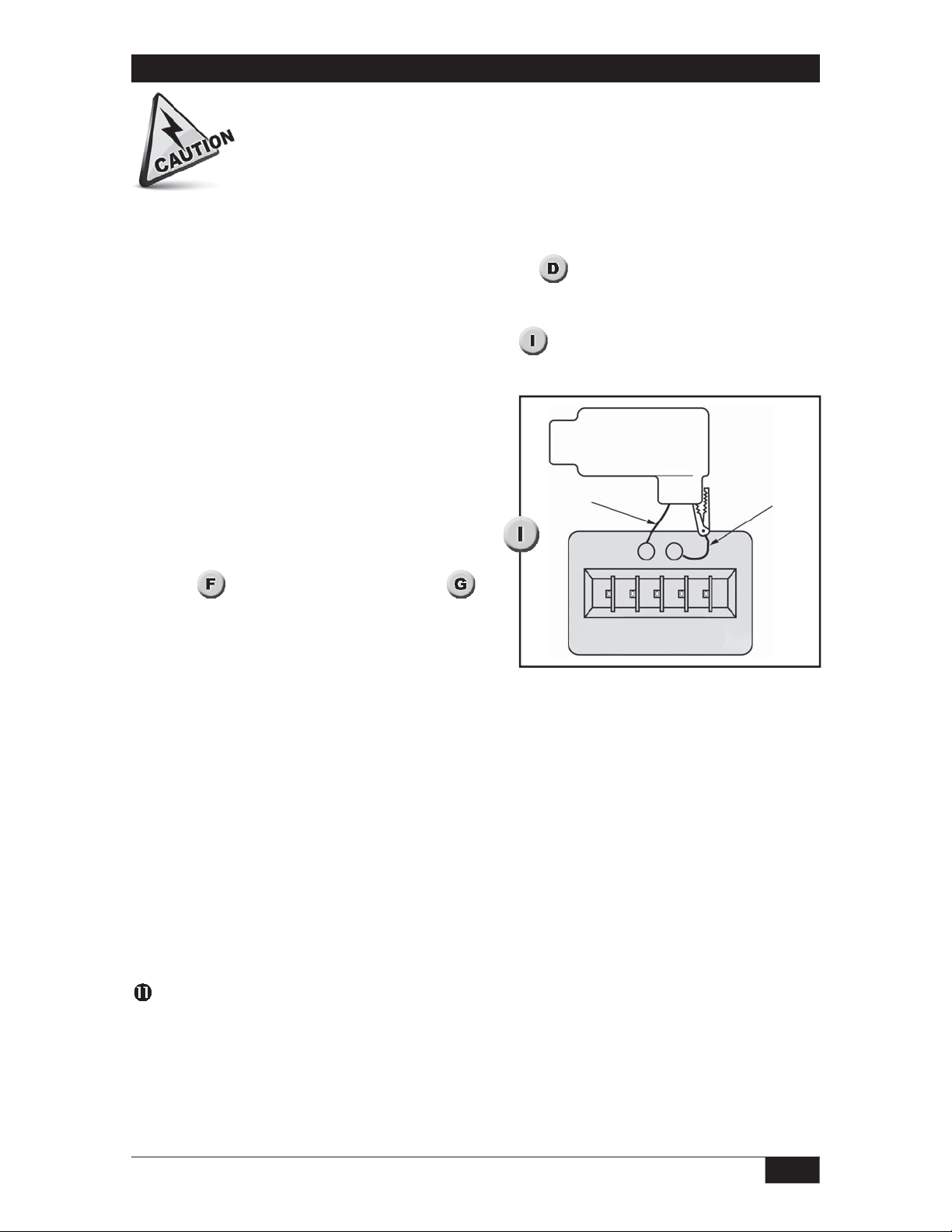
Remove the sensor. (Unscrew the sensor from the housing. Disconnect the ring
terminal or banana plug from the sensor end.)
Connect power and a current meter to the unit per . Connect a capacitor
substitution box (available from SOR) to the circuit to simulate the probe. Connect the
probe lead to one terminal of the capacitor substitution box, and connect the other
terminal of the box to the control housing. (See
eliminate any stray capacitance which may affect the calibration.
Set the capacitance box to desired zero level
capacitance.
Rotate ZERO and SPAN fine adjustment
potentiometers (pots) at least 22 turns
counter-clockwise.
) Use short connection wires to
Capacitance
SORtrax
Probe Wire
Substitution
Connection
Ground Wire
Zero Adjustment (4 mA)
Close ZERO switch #1 and SPAN switch #1.
(See
View the reading on the current meter. If the
output is less than 4 mA, turn the fine ZERO
) Open all other switches per .
Capacitor
Substitution Box
adjustment clockwise until 4 mA is reached.
NOTE: Only one ZERO switch may be in the closed position at any time.
If the output is greater than 4 mA, (opening the previous switch) close each coarse
adjustment switch, one at a time, until a reading less than 4 mA is reached. Turn the
fine ZERO adjustment clockwise until 4 mA is reached.
NOTE: If 4 mA cannot be obtained, please see the trouble shooting chart on page 14.
Span Adjustment (20 mA)
Set the capacitance box to the desired maximum capacitance value.
Ensure SPAN coarse adjust switch #1 is in the closed position, with all other switches open.
Rotate the SPAN fine adjustment pot clockwise until the meter indicates 20 mA. If a 20
mA reading cannot be obtained, proceed to step 11.
Open SPAN switch #1 (coarse) and close SPAN switch #2. Repeat step 10. If a 20 mA
reading cannot be obtained, repeat the procedure closing switch #3 or #4 until 20 mA
is indicated.
NOTE: Only one SPAN switch may be in the closed position at any time.
NOTE: If 20 mA cannot be obtained, please see the troubleshooting chart on page 14.
If the zero setting is changed, the span will change, and the unit must be recalibrated.
Form 837 (05.13) ©SOR Inc.
5/16
Page 6
Blind Calibration
Electrical power must be disconnected from explosion proof models before
the cover is removed. Failure to do so could result in severe personal injury
or substantial property damage.
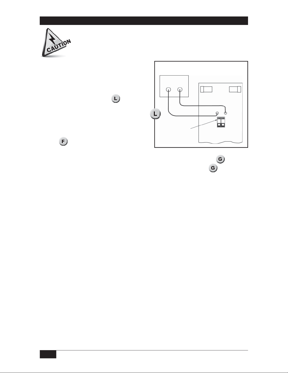
Use this calibration method when it is not possible
to raise or lower the level of the process in the
vessel or tank. Do not permanently install the unit
until after setting the ZERO (4 mA) point.
Current Meter
- +
M- and M+ optional
wiring diagram
Use the wiring configuration in when the
loop cannot be conveniently opened for current
monitoring. Attach a current meter as shown.
Turn both potentiometers (fine adjustments
for ZERO and SPAN) fully counterclockwise.
(See
)
TB1
Loop Power
Terminal Block
M- M+
Control
Board
Zero Adjustment (4 mA)
Close switch #1 on coarse adjustment switches for ZERO and SPAN. (See )
Open switches #2, #3, and #4 on both coarse adjustment switches per .
With the end of the probe just touching the process, view the output. If the output is
less than 4 mA, turn the fine ZERO adjustment clockwise until 4 mA is reached.
NOTE: Only one ZERO switch may be in the closed position at any time.
If the output is more than 4 mA, (opening the previous switch) close each coarse
adjustment switch individually until a reading less than 4 mA is attained. Turn the fine
ZERO adjustment clock-wise until 4 mA is reached.
NOTE: If 4 mA cannot be obtained, see the troubleshooting chart on page 14.
Span Adjustment (20 mA)
Calibrate for span by determining the present level in the tank, and setting the span
proportionally. For best results, the level should be at 50% or greater.
Determine the level present in the tank. Complete the unit installation, except for the
housing cover.
Calculate the expected current output using the following formula: 20mA x (% of tank
fill) 20mA = output.
For example: Tank level is at 50%, set SPAN coarse and fine for 20mA reading (16mA x
50% + 4mA, If the material level is at 90%, set the span adjustment for 18.4 mA (16mA
x 90% + 4mA, The 100% fill level should be verified at the earliest opportunity.
If the zero setting is changed, the span will change, and the unit must be recalibrated.
6/16
Form 837 (05.13) ©SOR Inc.
Page 7

Probe and Transmitter Performance Veri cation
Probe Check Remove the transmitter from the probe. With no process on the probe, check
the resistance from the probe to ground. Resistance less than 1MΩ indicates leakage in the
probe. With process touching the probe, check the resistance from the probe to ground.
Resistance of 100KΩ or less in the case of a bare probe with conductive material indicates
that an insulated probe is required. In any other case, a defect in the probe is indicated.
Transmitter Drift Check If the output of the transmitter is drifting, it is important to verify
if the drift is due to the probe or the transmitter. If the probe is connected and installed
properly, it will not drift.
Remove the probe from the transmitter. Without touching the calibration settings, connect
a capacitance across the probe to ground input. See Figure 9 on page 5. Change the
capacitance until the transmitter output is 4.00 mA. Observe the zero point reading for
twenty four hours. If the reading is stable, then the probe or the application is the source
of the drift.
CE Mark Installation
When subjected to an RF interference, the 670K9
will maintain the +/-1% accuracy in all frequency
ranges with the following exception:
The unit is susceptible to a conducted RF
interference in the range of 31-40MHz, reducing
the accuracy to +/-1.3%. The +/-1% accuracy is
maintained above and below this range.
In order to achieve the stated accuracy for 670K9,
a shielded cable, cable gland, shield beads, and
the probe should be mounted in a metallic vessel.
SOR recommends using a shielded cable made
of PVC insulation around a tinned copper braid
shield (Olflex CY cable or equivalent). Refer to
illustrations for installation of shield beads.
Install end of bead
as close to cable
gland as possible
2 Loops
POSITIVE
NEGATIVE
1 Loop
POWER WIRE
SHIELD BEAD
2 Loops
Long/Slender
bead
PROBE WIRE
SHIELD BEAD
Short/Fat bead
Form 837 (05.13) ©SOR Inc.
7/16
Page 8

SOR RF Probe Grounding Scheme
Power Supply
Do not provide separate earth grounding
for the process connection. This can
create a parallel grounding circuit
that will impair operation and calibration.
IMPORTANT! Do not
provide separate earth
grounding for the process
connection. This can create
a parallel grounding circuit
that will impair operation
and calibration.
SOR RF Probe Grounding Scheme
Critical Grounding Path =
Circuit
Board
Line
Neutral
Ground
Line
Neutral
Ground
Electronics
Housing
Connection
Process
SOR Supplied
Stilling Well
(optional)
Probe Center
Conductive Element
8/16
Form 837 (05.13) ©SOR Inc.
Page 9

Control Drawing
Form 837 (05.13) ©SOR Inc.
9/16
Page 10

Control Drawing
10/16
Form 837 (05.13) ©SOR Inc.
Page 11

Control Drawing
Form 837 (05.13) ©SOR Inc.
11/16
Page 12

Troubleshooting
Symptom/Problem Possible Cause Corrective Action
Not current in the loop 1. Power supply turned off
2. Improper wiring at TB1
3. Excessive loop resistance
Zero point cannot be
set to 4.00mA at low
level
Span point cannot be
increased to 20mA at
high level
Span point cannot be
decreased to 20mA at
high level
1. Fine zero incorrect
2. Probe capacitance greater
than 500pF when coarse
ZERO switch #4 is closed (all
other switches open)
1. Insufficient probe
capacitance
2. Excessive loop resistance
3. Incorrect calibration
1. Low probe resistance to
ground
2. Probe capacitance greater
than 2,000pF
1. Check power supply
2. Check electrical connections,
figure 4
3. Reduce loop resistance or adjust
power supply
1. Check calibration
2. Use smaller diameter probe or
replace bare probe w/insulated probe
or locate probe farther from the
vessel wall or consult the factory
1. Increase probe diameter or use
probe w/higher dielectric insulation
or locate probe closer to vessel wall
or install a stilling well or consult the
factory
2. Reduce loop resistance or adjust
power supply
3. Check calibration
1. Consult the factory
2. Use a smaller diameter probe or
replace bare probe w/insulated probe
or locate the probe farther from the
vessel wall
Transmitter output is
20mA or greater when
the vessel is not full
Erratic transmitter
output
Drifting transmitter
output
Non-linear output 1. Extreme material build-up
1. Incorrect calibration
2. Probe shorted to ground
3. Material build-up on probe
1. Turbulent process
2. Radio frequency
interference
3. Probe moving within the
vessel
1. Process material
properties are changing
2. Probe insulation is eroded
3. Transmitter malfunction
2. Non-parallel surfaces near
the probe
3. Conducting liquid in an
ungrounded vessel, eg:
fiberglass tank
1. Recalibrate
2. Replace the probe
3. Clean probe and replace or
possible misapplication, consult
the factory
1. Install a stilling well
2. Install RFI/EMI filters
3. Improve probe anchoring
1. Consult the factory
2. Verify probe integrity
3. Consult the factory
1. Consult the factory
2. Mount the probe in a better
location or install a stilling well, or
install a probe with a ground rod
3. Connect earth ground to
instrument ground
12/16
Form 837 (05.13) ©SOR Inc.
Page 13
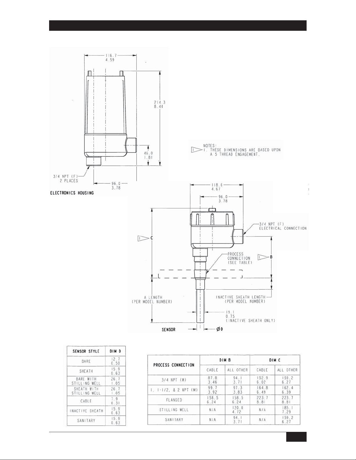
Dimensions
R Housing Con guration (Explosion Proof Remote)
Dimensions are for
reference only.
Contact the factory
for certified drawings
for a particular model
number.
Linear = mm/inches
Drawing 0390653
Form 837 (05.13) ©SOR Inc.
13/16
Page 14

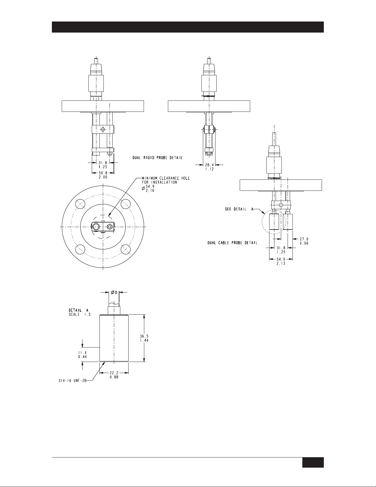
Dimensions
K Housing Con guration (Explosion Proof Remote)
Dimensions are for reference only.
Contact the factory
for certified drawings
for a particular model number.
Linear = mm/inches
Drawing 0390654
14/16
Form 837 (05.13) ©SOR Inc.
Page 15
Dimensions
Other Sensors
Form 837 (05.13) ©SOR Inc.
Dimensions are for reference only.
Contact the factory for certified drawings
for a particular model number.
Linear = mm/inches
Drawing 0390654
15/16
Page 16

Printed in USA www.sorinc.com
14685 West 105th Street, Lenexa, KS 66215 913-888-2630 800-676-6794 USA Fax 913-888-0767
16/16
Registered Quality System to ISO 9001
Form 837 (05.13) ©SOR Inc.
 Loading...