

Page 1
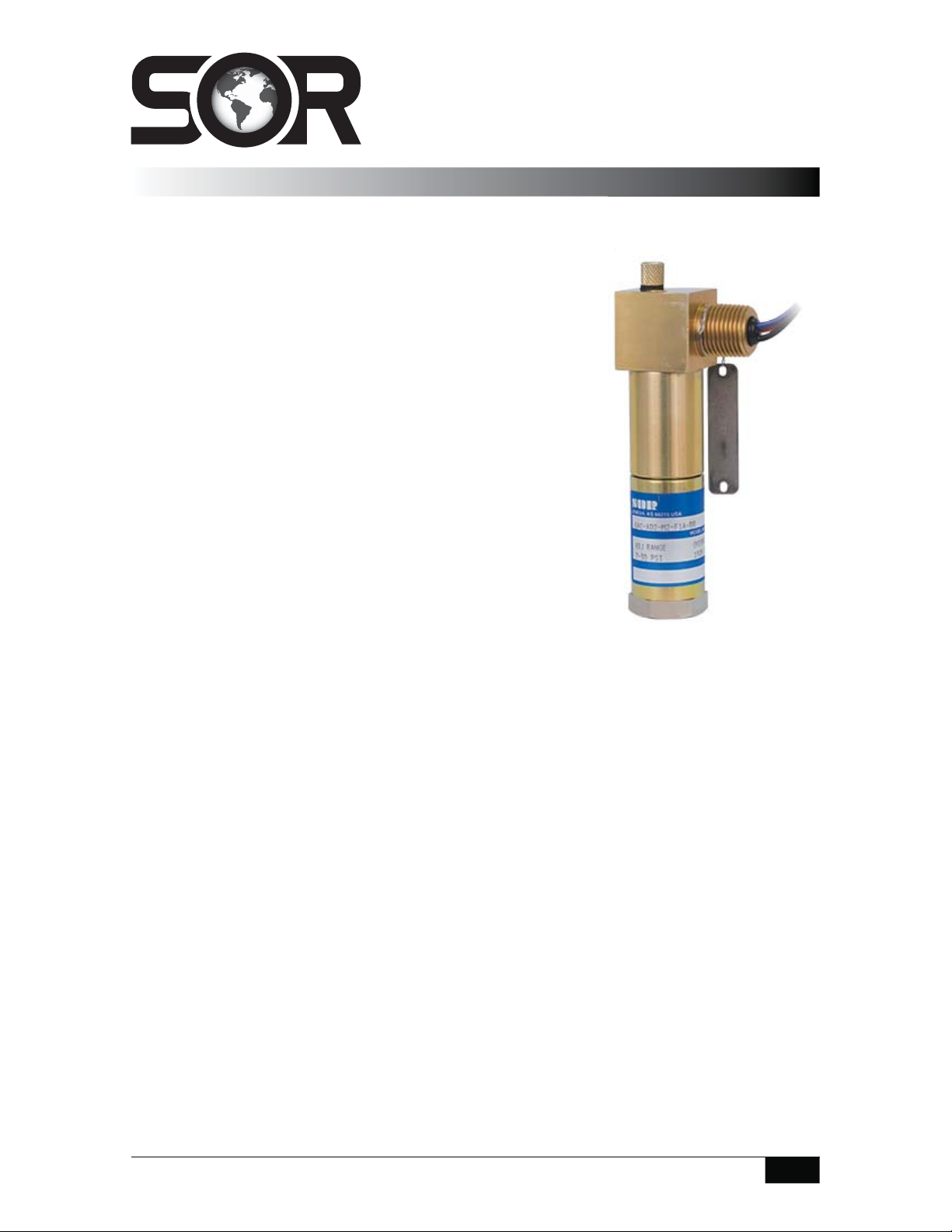
OMNI Pressure Switch
General Instructions
This instruction covers installation, process connection, electrical
®
connection and calibration of the SOR
Omni pressure switches.
al
.
Static“O”Ring Type (prefaced by 5, 6, 9 or 1)
The Static“O”Ring type pressure switch with optional wetted
parts is suitable for a wide variety of process applications.
This type is not recommended for high-pressure fluid power
applications where high shock pressure and high cycle rates
are expected. Use the SOR Pivot Seal type (prefaced by 2 or 3)
for fluid power applications.
The pressure sensing element of the Static“O”Ring type
pressure switch is a force-balanced, piston-actuated assembly
sealed by a flexible diaphragm and o-ring. Media pressure
on the area of the piston counteracts the force of the range
spring, adjustable by the adjusting screw, which moves the
piston shaft only a few thousandths of an inch to directly
actuate the electrical snap-action switching element. This
principle of operation virtually eliminates friction and resultant wear.
Pivot Seal Type (prefaced by 2 or 3)
The Pivot Seal type pressure switch is generally suitable for fluid power hydraulic
applications where high shock pressures and high cycle rates are expected and where
only normally industrial clean hydraulic fluid is used. Use Static“O”Ring type for other
process applications.
The pressure sensing element of the Pivot Seal type pressure switch is a force-balanced,
piston-actuated assembly sealed by an o-ring. The piston reciprocates a maximum of
.020 inches. This results in minimal o-ring wear. Media pressure on the area of the piston
counteracts the force of a range spring, adjustable by the adjusting screw, which moves the
piston shaft and the force transmitter to directly actuate the electrical snap-action switching
element. This principle of operation greatly reduces the friction and resultant wear normally
associated with piston-type pressure switches.
NOTE: If you suspect that a product is defective, contact the factory or the SOR Representative
in your area for a return authorization number (RMA). This product should only be installed by
trained and competent personnel.
Design and specifications are subject to change without notice.
For latest revision, go to sorinc.com
Form 463 (05.13) ©SOR Inc.
Registered Quality System to ISO 9001
1/4
Page 2
Installation
The pressure switch may be line mounted by either rigid process piping or the electrical
conduit. The body of the pressure switch should be clamped to a suitable support member
on applications where either rigid process piping or electrical conduit is not available.
When rigid process piping or rigid electrical conduit is used it is important
that no bending or torsional forces be imposed on the pressure switch.
Safety Integrity Level (SIL) Installation Requirements
The SOR pressure switches have been evaluated as Type-A safety related hardware.
To meet the necessary installation requirements for the SIL system, the following
information must be utilized:
Proof Test Interval shall be one year.
Units may only be installed for use in Low Demand Mode.
Products have a HFT (Hardware Fault Tolerance) of 0, and were evaluated in a
1oo1 (one out of one) configuration.
Form 1538 (03.12) ©2012 SOR Inc.
Process Connection
Use two wrenches when connecting process pipe: a 1-1/8” open-end wrench to hold the
hex pressure port while connecting the process pipe, the other wrench to tighten the
process pipe or tube fitting.
Do not use a pipe wrench or strap wrench on the round body or square
switching assembly while tightening the process pipe or tube tting. Use
wrench ats on process port only!
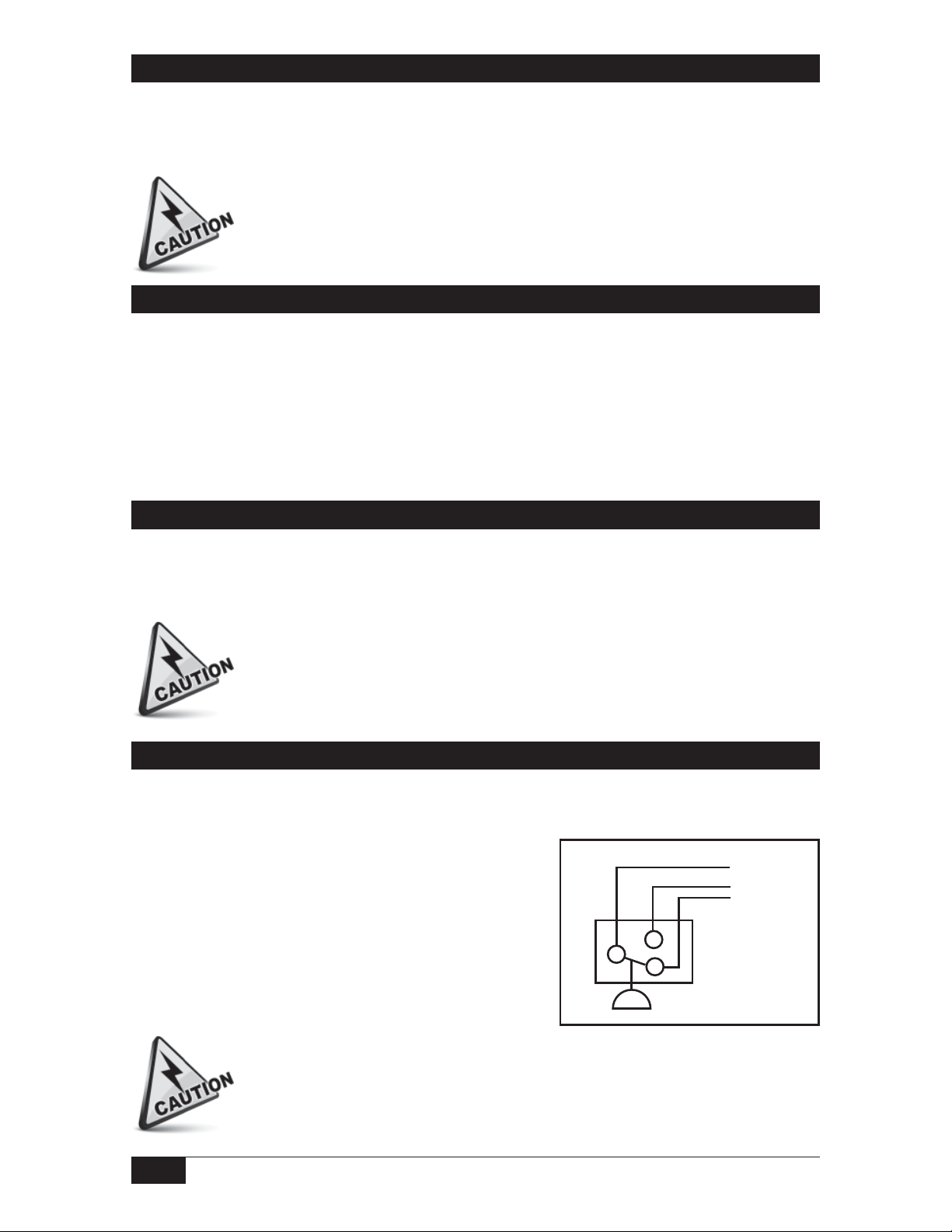
Electrical Connection
Omni pressure switches have 18” potted free leads of 18 AWG stranded copper wire. They
are marked NC – Normally Closed; NO – Normally Open; and C – Common.
Electrical switching elements are snap action SinglePole, Double-Throw (SPDT). (Termination: 1/2NPT(M)
conduit connection with free leads)
Use a 1-1/4” open-end wrench to hold the square
portion near the electrical connection while conduit
fitting is being tightened. Connect free leads as desired.
Pressure
Blue (C)
Black (NO)
Red (NC)
2/4
Care must be taken to ensure clearance is provided to prevent sharp objects
from cutting or abrading wire insulation.
Form 463 (05.13) ©SOR Inc.
Page 3

Calibration
Factory Preset units have been set at the SOR factory to customer specifications and
are tamper-proof. The set point is locked and sealed. It cannot be changed in the field.
TP accessory designator indicates factory preset.
Field Adjustable units have a recessed Allen screw for set point adjustment. Remove
knurled cap and adjust the set point as follows:
Use 1/8” hex Allen wrench to turn adjusting screw to achieve desired set point.
Turn adjusting screw clockwise (in) to increase set point.
Turn adjusting screw counterclockwise (out) to decrease set point.
Use an external pressure measuring device to accurately calibrate set points.
NOTE: SOR discourages eld modi cations, change-out of wetted parts, or repair. It is
preferred that products be returned to SOR for inspection or repair. Contact the factory for
return authorization. Field repair should be performed by quali ed instrument technicians
with adherence to SOR procedures.
Form 463 (05.13) ©SOR Inc.
3/4
Page 4

Dimensions
Dimensions are for reference only.
Contact the factory for certified drawings for a particular model number.
Linear = mm/inches
Drawing 0090179
sorinc.com
14685 West 105th Street, Lenexa, KS 66215 913-888-2630 800-676-6794 USA Fax 913-888-0767
4/4
Registered Quality System to ISO 9001
Form 463 (05.13) ©SOR Inc.
 Loading...