

Page 1
660
Multipoint
Electronic Level Switch
General Instructions
The Multipoint Electronic Level Switch is a level sensing device which reads
process level by capacitance measurement.
Capacitance varies according to the height of the process inside the vessel.
Capacitance variation in the circuit is electronically monitored, and DPDT
relay contacts change state at user selected set points to signal process
presence at specific process levels.
For example, when process level rises to set point 4, relay 4 changes state to signal process presence at set point 4. The DPDT relay 4 maintains its state as long
as process level is above set point 4. When process level falls below set point 4,
relay 4 contacts return to their original state.
NOTE: If you suspect that a product is defective, contact the factory or the SOR®
Representative in your area for a return authorization number (RMA). This product
should only be installed by trained and competent personnel.
Design and
specifications are
subject to change
without notice.
For latest revision, go to
www.sorinc.com
Table of Contents
Sensing Level Con guration ......................2
Adjustable Differential Set Points ................2
Set up ................................................. 3
Probe Installation ................................... 3
Installation of Separate Electronics Housing ... 3
Remote Cable Connection ......................... 3
Electrical Supply/Control Cable Connection .... 4
Probe Set up Overview and Considerations .... 6
Probe Tip Termination Notes ...................... 7
Actual Level Set up .................................8
Calculated Set up ...................................9
Calculated Set up Worksheet Sample ......... 13
Model 661 Set pt. Set up and Output Wiring . 14
Model 662 Set pt. Set up and Output Wiring . 16
Model 663 Set pt. Set up and Output Wiring . 18
Model 664 Set pt. Set up and Output Wiring . 20
Model 665 Set pt. Set up and Output Wiring . 22
Model 666 Set pt. Set up and Output Wiring . 24
Model 667 Set pt. Set up and Output Wiring . 26
Model 668 Set pt. Set up and Output Wiring . 28
Control Drawings ................................. 31
Dimensions ........................................ 33
Form 677 (05.13) ©SOR Inc.
Registered Quality System to ISO 9001
1/36
Page 2
Sensing Level Con guration
The number of set points and their configuration depends upon the model number specified for manufacture. Compare the first three numbers from the nameplate model number
to
to find the sensing level configuration for the unit to be installed.
Models 661 through 664 provide fixed, narrow differential set points only. For each fixed
differential set point, relay operation is centered on a single point. After set up, the single
point of relay operation can be set anywhere on the probe by adjusting the appropriate set
point potentiometer (pot).
Adjustable Differential Set Points
Models 665 through 668 include an adjustable differential set point. For the adjustable differential set point, the adjustable differential relay is controlled by two limits. The adjustable
differential relay changes state when process level reaches the upper limit of the adjustable
differential set point.
The adjustable differential
relay maintains its state until
process level falls below the
lower limit of the adjustable
differential set point. When
process level falls below the
lower limit of the adjustable differential set point,
the adjustable differential
relay contacts return to their
original state.
The upper limit can be set
anywhere on the probe by
adjusting potentiometer (pot)
2. The lower limit can be set
anywhere on the probe by
adjusting potentiometer (pot)
3. The adjustable differential
set point provides a single
set of contacts to control
cut—in and cut—out of filling (or emptying) equipment.
Model 661
Adjust Pot 1
Term Strip 1
Model 665
Adjust Pot 2
Term Strip 2
Adj Diff
Adjust Pot 3
Model 662
Adjust Pot 1
Term Strip 1
Adjust Pot 2
Term Strip 2
Model 666
Adjust Pot 1
Term Strip 1
Adjust Pot 2
Term Strip 2
Adj Diff
Adjust Pot 3
Model 663
Adjust Pot 1
Term Strip 1
Adjust Pot 2
Term Strip 2
Adjust Pot 3
Term Strip 3
Model 664
Adjust Pot 1
Term Strip 1
Adjust Pot 2
Term Strip 2
Adjust Pot 3
Term Strip 3
Adjust Pot 4
Term Strip 4
Model 667 Model 668
Adjust Pot 1
Term Strip 1
Adjust Pot 2
Term Strip 2
Adj Diff
Adjust Pot 3
Adjust Pot 4
Term Strip 4
Adjust Pot 2
Term Strip 2
Adj Diff
Adjust Pot 3
Adjust Pot 4
Term Strip 4
Model 666 through 668 sensing level configurations provide an adjustable differential set
point for vessel level control as well as one or two fixed differential set points for Hi—Hi
and Lo—Lo level alarm or shutdown circuits.
2/36
Form 677 (05.13) ©SOR Inc.
Page 3
Set up
Review Probe set up overview and considerations on page 6 to determine the best approach to set up. Two set up methods are possible. Actual Level set up begins in the right
column on page 8. Calculated Level set up begins in the left column on page 9.
Review both methods. Actual Level set up is preferred, but may not be practical for all
installations.
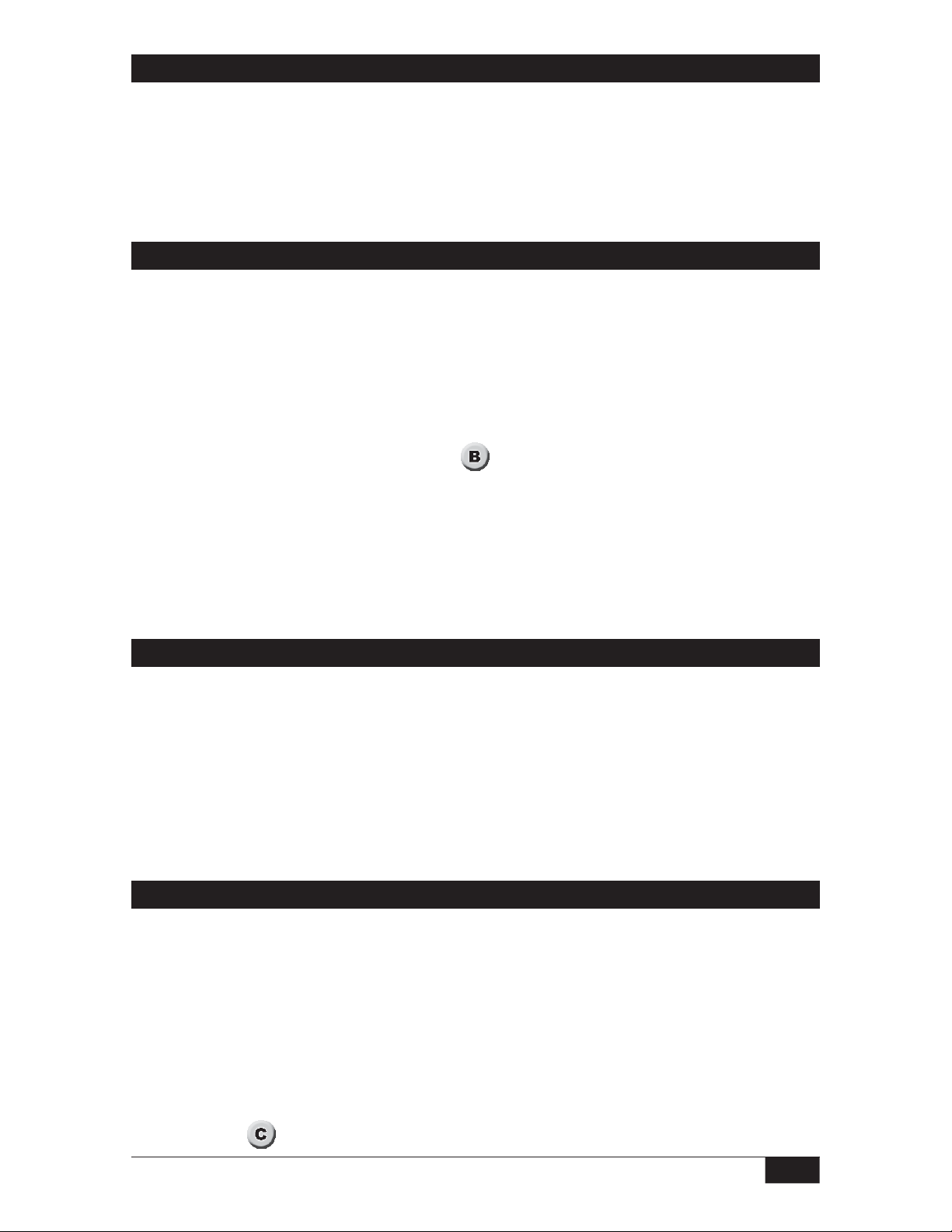
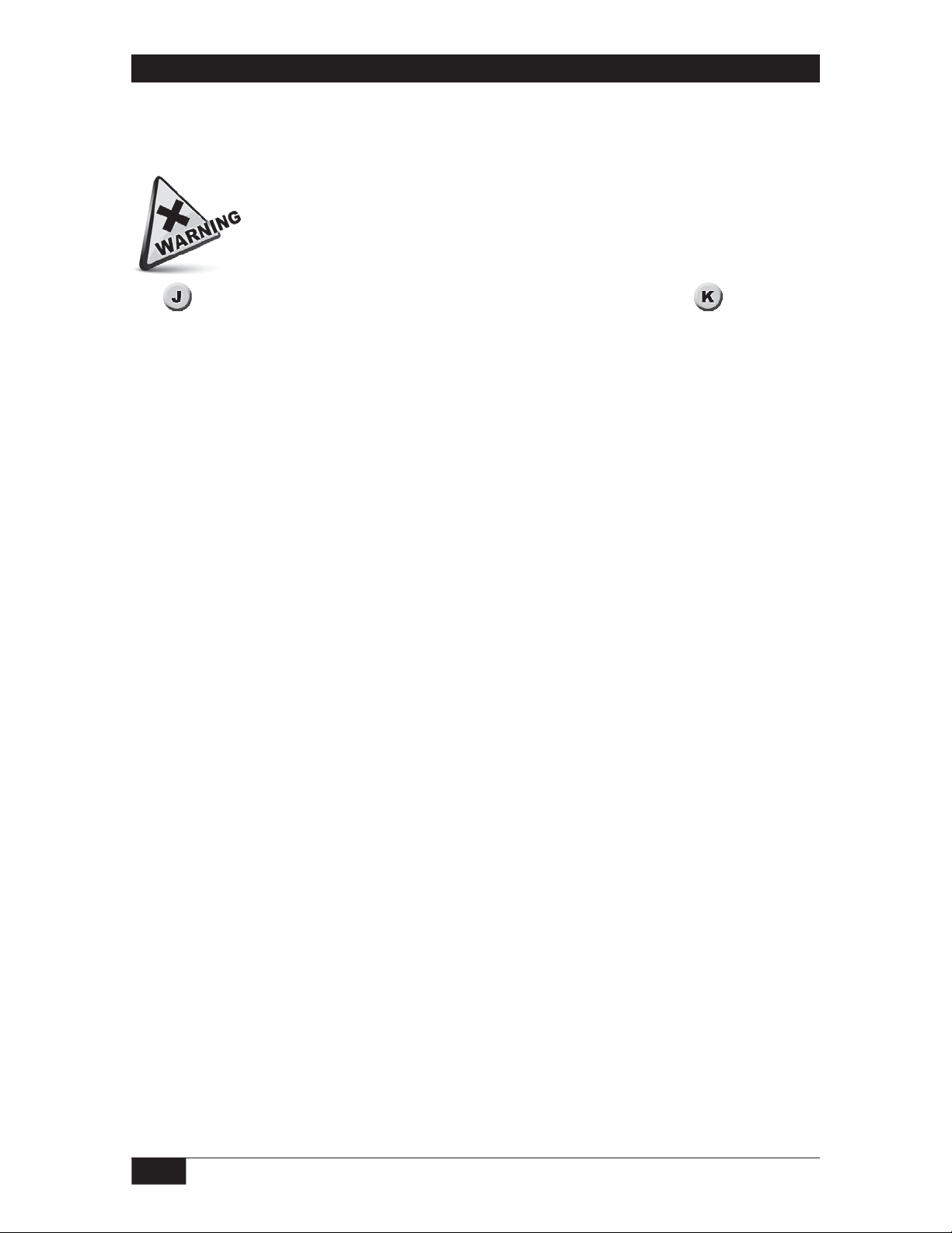
Probe Installation
All models
Probes are mounted vertically from the top of a vessel. The probe must be electrically
isolated from the vessel; make no connection between the probe and the vessel other than
the process connection and (if applicable) the threaded weight at the probe tip. Do not weld
any part of this instrument.
Make sure that the sensor can be fully inserted and tightened without interference from
obstructions inside the tank or vessel. (See
inlet fill paths. Spray from a fill path can cause false level indications.
) The probe should be mounted away from
Insert coated probes carefully to prevent damage to the probe coating.
For pressurized vessels, seal the flanged or threaded process connection to prevent leakage.
Do not use the sensor base as a handle to tighten a threaded process connection.
Use a suitable wrench on the flats to tighten a threaded probe into the process connection.
Use suitable mounting bolts to mount a flanged probe on a flanged process connection.
Installation of Separate Electronics Housing
Explosion Proof Electronics Housing (Model 66R)
The explosion proof electronics housing can be line mounted. Alternatives to line mounting
are surface mounting or pipe mounting if appropriate accessory hardware was specified.
Weathertight Electronics Housing (Model 66W)
The weathertight electronics housing can be surface mounted using #10 or M6 bolts
through the mounting pads. Recommended mounting orientation is horizontal with cover
hinges at 12 o’clock. Allow headroom for cover swing.
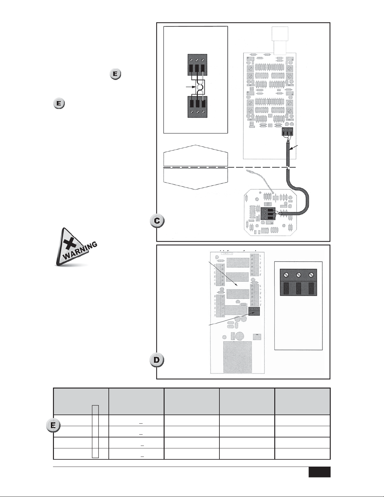
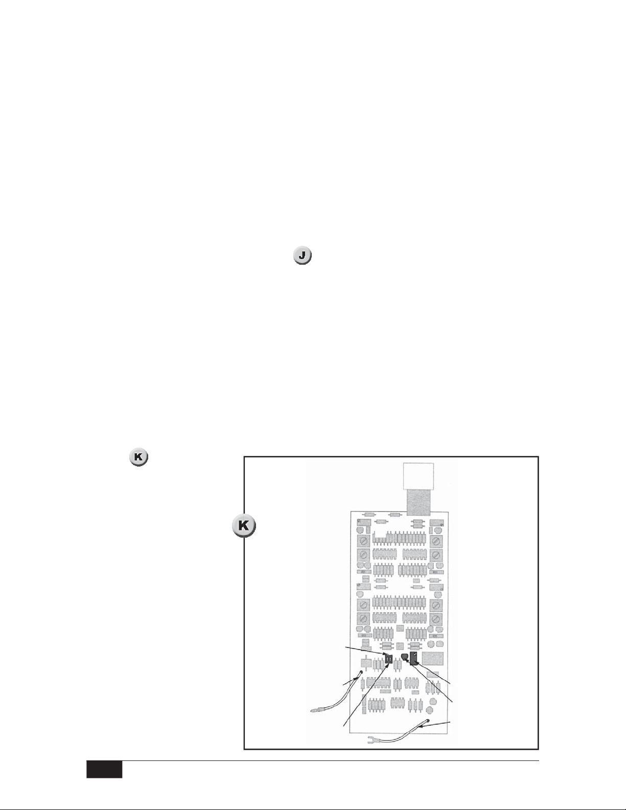
Remote Cable Connection
Models 66R, 66W
Install conduit between the remote probe housing and the separate electronics housing.
In order to maintain explosion proof ratings in hazardous areas, the conduit system must
meet or exceed any explosion proof requirements for the location.
Fish 22/2 shielded twisted pair signal cable through the conduit between the housings.
The terminal block on the set point adjustment board (in the electronics housing) must be
connected to the terminal block on the probe adjustment board (in the remote probe
housing). (See
Form 677 (05.13) ©SOR Inc.
)
3/36
Page 4
Connect the shield to GND on the set point adjustment board and on the probe adjustment
board.
Connect the +12 terminal on the set point adjustment board to the +12 terminal on the
probe adjustment board.
Connect the SIG terminal on the set point adjustment board to the SIG terminal on the
probe adjustment board. (See
detail.)
3/4” NPT(F) Conduit Connections
Electrical power must be
disconnected from explosion proof models before the
cover is removed. Failure to
Model 66
66
R,
W
do so could result in severe
personal injury or substantial
property damage.
Ensure that wiring conforms
Process
Connection
to all applicable local and
national electrical codes and
install unit(s) according to
relevant national and local
safety codes.
Probe shaft
must not
short
to tank
Electrical Supply / Control Cable Connection
1” NPT(F)
Conduit
Connection
Wrench Flats
Top of Vessel
No obstructions
Model 66
J
Hex
Process
Connection
Probe shaft
must not
short
to tank
Model 66J
Install conduit and fish cables to carry supply and control conductors into the integral
housing.
Models 66W, 66R
Install conduit and fish cables to carry supply and control conductors into the separate
electronics housing.
All Models
A three-position terminal strip located on the power supply/relay output board provides
connections for Line Power and Ground. Terminal positions are labeled on the circuit board
as shown in the
4/36
detail.
Form 677 (05.13) ©SOR Inc.
Page 5
Make sure that field power
matches the instrument’s power
requirements. The fifth place
designator in the nameplate
model number specifies power
requirement. (See ) Make
connections to +/L1 and —/L2/
Neutral terminals according to
.
Terminal Connection Detail
SIG
+12
GND
Shield
The housing and the PC Board
must be connected to ground.
Ground (earth) screws are
provided on the three-position
PC board terminal strip and on
the housing floor. Control Cable
connection is detailed later in
these instructions, after probe
set up and set point adjustment.
This product must be installed
with an explosion proof breather
vent per Agency requirements
and the national Electric CodeArticle 501, Section F,
paragraph 3.
SIG
+12
GND
Set point adjustment board
in electronics housing
Probe adjustment board
in probe housing
Power supply/relay
output board
Power supply
terminal strip
location
Up to 4000’
22/2 twisted
pair
shielded
+ / L1
Power supply
terminal strip detail
GND
- / L2 Neutral
Fifth Place
Designator
or 6 6
5
6
7
8
Form 677 (05.13) ©SOR Inc.
Power Supply
Requirement
12 VDC +10% 245 ma 12 VDC+ 12 VDC Gnd
24 VDC +10% 243 ma 24 VDC+ 24 VDC Gnd
120 VAC +10% 74 ma Line Neutral
240 VAC +10% 36 ma Line 1 Line 2
Maximum Current
Draw
Terminal +/L1
Connection
Terminal +/L2
Neutral
Connection
5/36
Page 6
Probe Set up Overview and Considerations
g
If the process can easily be raised and lowered during set up, use the Actual Level Set
up procedure. During Actual Level Set up, the process must be positioned to maximum
level and to each set point level as briefly outlined in
procedure on page 8.
If the process cannot easily be raised and lowered during set up, use the Calculated Set
up procedure. During Calculated Set up, picofarad readings are taken at two levels.
The readings are used to calculate the picofarad value for maximum level as well as the
picofarad value for each set point level. Begin the Calculated Set up Procedure on page 9.
Units in Hazardous Locations — Prior to calibration, make sure that the
work area is declassi ed before removing the explosion proof cover to
calibrate the unit. Failure to do so could result in severe personal injury
or substantial property damage.
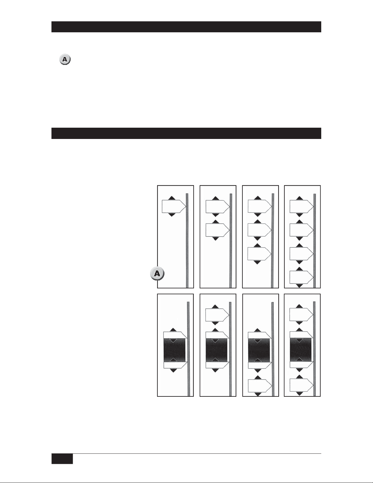
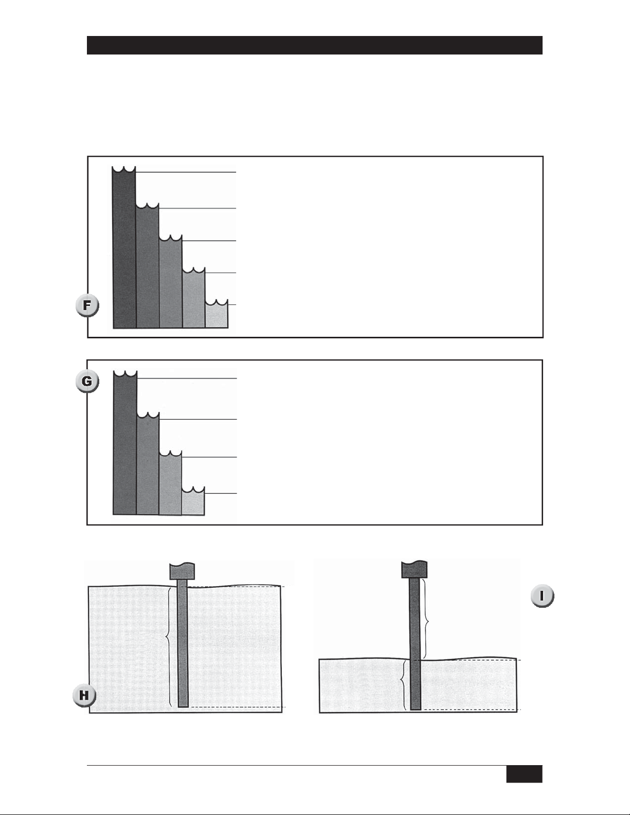
The Actual Level Set up procedure and the Calculated Set up procedure are designed
to yield maximum set point adjustability. In both procedures (Actual Level Set up and
the Calculated Set up), the active area of the probe is spanned to maximum process level.
(Step 1
unlimited up to maximum vessel level (
) When the span is set to maximum vessel level, set point adjustability is
).
. Begin the Actual Level Set up
By spanning the probe only as high as the uppermost set point level (instead of maximum
level - see
), set point adjustability is restricted, but set point resolution is optimized.
To modify the Actual Level Set up procedure for optimal resolution, set the threshold for
probe span and the threshold for the uppermost set point while the process is steady at the
uppermost set point level. (See modification to Step 1
)
To modify the Calculated Set up procedure for optimal resolution, use the picofarad value
for the uppermost set point as the picofarad value for maximum level.
and
illustrate the effect of span on resolution. Note on that set points cannot
be positioned above the uppermost set point. If future requirements call for a set point that
is higher than the current uppermost set point, the probe will have to be re-spanned to the
new uppermost set point level (or to maximum level).
6/36
Form 677 (05.13) ©SOR Inc.
Page 7
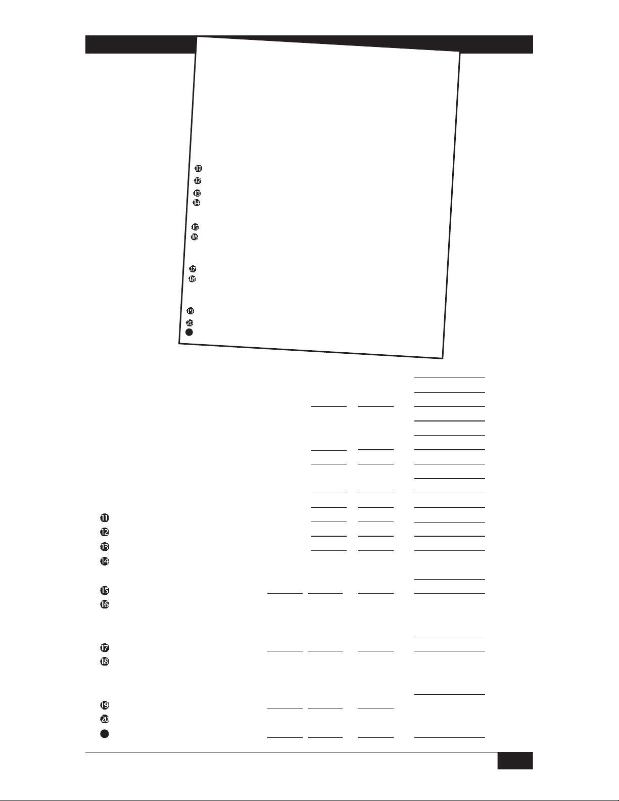
Probe Tip Termination Notes
For sheath probes, the last inch of the rigid probe is inactive.
The flexible probes terminate with inactive 316SS weights. The weights are insulated
from the probe, and 3/4-16 UNF threads are provided for connection to locally provided
anchoring hardware.
Step 1 At maximum level adjust probe span.
Step 2 At uppermost set point level adjust set point.
Step 3 At second set point level adjust set point 2.
(If applicable)
Step 4 At third set point level adjust set point 3.
(If applicable)
Step 5 At fourth set point level adjust set point 4.
(If applicable)
Maximum level
Probe Span
Set points can
be positioned
anywhere within
span without
resetting
probe span
Combine At uppermost set point level adjust probe span.
Step 1 & 2 Then: adjust set point 1.
Step 3 At second set point level adjust set point 2
(If applicable)
Step 4 At third set point adjust set point 3.
(If applicable)
Step 5 At fourth set point adjust set point 4.
(If applicable)
Resolution
100%
90 %
80%
70%
60%
50%
40%
30%
20%
10%
0%
Uppermost set point
Probe Span
Set points can
be position only
within span
Inactive portion
of probe above
probe span
Resolution
100%
80%
60%
40%
20%
0%
Form 677 (05.13) ©SOR Inc.
7/36
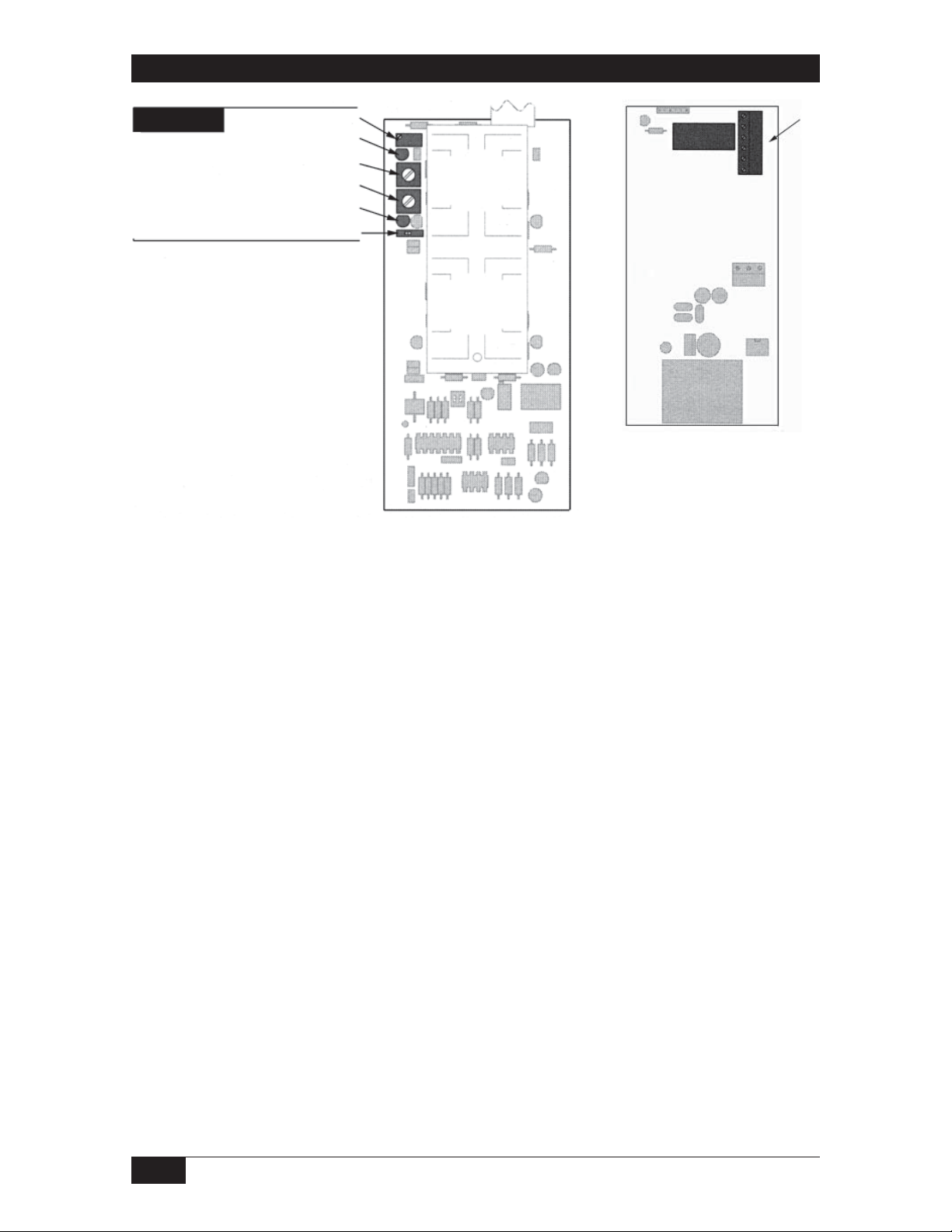
Page 8
Actual Level Set up
For Actual Level Set up, the process must be positioned to maximum level to set the probe
span. The process is then lowered to each set point in turn, and at each stop the
appropriate set point threshold is adjusted.
Units in Hazardous Locations — Prior to calibration, make sure that the
work area is declassi ed before removing the explosion proof cover to
calibrate the unit. Failure to do so could result in severe personal injury or
substantial property damage.
See to locate adjustments when setting up a remote mounted probe. See to locate
adjustments when setting up an integrally mounted probe. (If process level cannot be raised to
maximum level or conveniently moved to desired set point levels, use the Calculated procedure
on next page.) Before starting the Actual Level procedure, make sure that the following steps
have been completed.
SPAN ADJUST
lnstrument installed with power applied.
Process steady at maximum level.
Probe span pot fully CCW (twenty five turns CCW).
Turn all set point adjust pots fully CCW (25 turns CCW).
Turn all on and off delay pots fully CCW (One turn pots).
Set all failsafe switches to LO position.
Both range selection DIP switches off (open).
Watch the probe loading LED:
LED is on — close DIP switch1 and go to step 2.
LED is off — go to step 3.
LED is on — close DIP switch 2 and go to step 3.
LED is off — go to step 3.
Turn the span pot CW until the probe loading LED lights, and then CCW to the point
where the LED goes off.
Slowly cycle the process up and down to verify the stability at which the LED goes off (per
your requirement).
SETPOINT ADJUST
Lower process to set point 1 level (set point 1 removed for model 665 & 667) and continue
on the page which matches the first three digits of the model number.
661........p. 14 662 ........ p. 16 663 .........p. 18 664 ....... p. 20
665........p. 22 666 ........ p. 24 667 .........p. 26 668 ....... p. 28
8/36
Form 677 (05.13) ©SOR Inc.
Page 9

Probe lead
Off (open) position
GND wire (shield drain)
Range selection DIP switches
(On/closed position)
Probe loading LED
Probe span pot
Calculated Set up
For Calculated set up, the capacitor substitution box is used to determine the picofarad
value of the process at two levels (A & B in the example
provide the rest of the values required for complete set up. See
when setting up a remote mounted probe. See
to locate adjustments when setting up
an integrally mounted probe.
). Subsequent calculations
to locate adjustments
Level A must be separated from level B by at least 5% of the length to be sensed. (At least
5% of 30’ in the example.)
Units in Hazardous Locations — Prior to calibration, make sure that the
work area is declassi ed before removing the explosion proof cover to
calibrate the unit. Failure to do so could result in severe personal injury or
substantial property damage.
Conditions required to begin Calculated set up:
lnstrument installed with power applied.
Process steady at Level A (10’ in the example ).
Span pot fully CCW (25 turns CCW).
Both range selection DIP switches off (open).
A sample worksheet is shown on page 13. The sample is filled out according to conditions
outlined in
. Level A must be greater than Level B for proper worksheet calculation. Any
unit of measure can be used with the Calculated Worksheet.
Enter the measurement for maximum level on line 8 of the worksheet.
Enter the value for level A on line 1 and the value for level B on line 2 of the
Calculated Worksheet.
Form 677 (05.13) ©SOR Inc.
9/36
Page 10
Set Threshold for Level A
Watch the probe loading LED:
LED is on — close DIP switch 1 and go to step 2.
LED is off — go to step 3.
LED is on — close DIP switches 1 & 2 and go to step 3.
LED is off — go to step 3.
Turn the span pot CW until the probe loading LED lights, and then CCW to the point
where the LED goes off.
Slowly cycle the LED on and off as required to find the precise threshold at which the LED
goes off. The instrument is now tuned to the picofarad value for Level A.
Find Picofarad value for Level A
For Models 66R, 66W
Refer to .
The probe is replaced by the capacitor substitution box to determine the picofarad value for
level A.
Remove three #6 Torx head screws and pull the PC board out of the remote probe housing.
Unplug the probe lead wire from the probe.
To place the capacitor substitution box into the circuit, clamp one of the alligator clips to
the mini-banana plug on the end of the probe lead wire. Clamp the other alligator clip to the
shield drain wire (ground) as it enters the signal cable terminal strip.
For Models 66J
Refer to
.
Pry the spring steel PC board
retaining clip off of the top of
the PC bracket assembly.
Unplug the ribbon connector and slide the set point
adjustment board up to access
the probe lead wire. Unplug
the probe lead wire from the
probe. Plug the ribbon connector back in.
Clamp one of the alligator
clips to the mini-banana plug
on the end of the probe lead
Range selection
DIP switches
[On (closed) position]
Probe lead
Probe span pot
Probe loading LED
wire. Clamp the other alligator
clip to the ground screw on
Off (open) position
Probe ground lead
the housing floor.
10/36
Form 677 (05.13) ©SOR Inc.
Page 11

All Models
p
The capacitor substitution box will inject capacitance, emulating the probe.
Using the thumbwheels on the capacitor substitution box, gradually increase the injected
capacitance until the probe loading LED lights.
Note the value on the substitution box thumb wheels when the probe loading LED lights;
record that value on line 4 of the worksheet. The recorded value is the picofarad value for
level A (2200 pf on page 12).
Take the alligator clip off of the probe lead, and plug the probe lead back into the probe.
Lower the process to Level B, and turn both DIP switches off (open).
Set Threshold for Level B
LED is on — close DIP switch 1 and go to step 2.
LED is off — go to step 3.
LED is on — close DIP switches 1 & 2 and go to step 3.
LED is off — go to step 3.
Turn the span pot CW until the probe loading LED lights, and then CCW to the point
where the LED goes off.
Slowly cycle the LED on and off as required to find the precise threshold at which the LED
goes off. The instrument is now tuned to the picofarad value for Level B.
Watch the probe loading LED:
Find Picofarad Value for Level B
Unplug the probe lead from the probe. Clamp the alligator clip to the mini-banana plug on
the end of the probe lead wire. (The other alligator clip should still be clamped to ground.)
Gradually increase the injected capacitance until the probe loading LED lights.
Note the value on the substitution box thumb wheels when the probe loading LED lights;
record that value on line 5 of the worksheet. The recorded value is the picofarad value for
level B (1900 pf on page 12).
Using the picofarad values for A and B, the picofarad per foot value can be interpolated,
and the picofarad value for maximum level can be extrapolated as shown in
the worksheet to find as many set point pf values as applicable.
Leave the alligator clip on the probe lead wire. The capacitor substitution box will be used
to inject the calculated values from the worksheet.
Form 677 (05.13) ©SOR Inc.
. Complete
11/36
Page 12

Calculated Probe Set up
ft
Inject the picofarad equivalent
of maximum level from line 11 of the
worksheet. Watch the probe loading LED:
LED is on — close DIP switch
1 and go to step 2.
LED is off — go to step 3.
LED is on — close DIP switches
1 & 2 and go to step 3.
LED is off — go to step 3.
Turn the span pot CW until the probe
loading LED lights, and then CCW to
the point where the LED goes off.
Slowly cycle the LED on and off
as required to find the precise threshold
at which the LED goes off.
Turn all set point adjust pots
fully CCW (25 turns CCW).
Turn all on and off delay pots
fully CCW (one turn pots).
Set all fail safe switches to
LO position.
Continue with Calculated set point set up
on the page which matches the first three
digits of the model number.
661.......p. 14
662.......p. 16
663.......p. 18
664.......p. 20
665.......p. 22
666.......p. 24
667.......p. 26
668.......p. 28
Solve for pf/ft.
Level A 10’ 2200pf
-Level B -8’ -1900pf
pf /ft. 2’ = 300pf
Solve for pf/1 ft.
pf 300 =150pf/ft.
ft. 2
Solve for C in ft.
Max Level 30ft.
-Level A -10ft.
C 20ft.
Convert C to pf
C 20ft.
x pf/ft. x150pf
C in pf 3000pf
Solve for Max Level in pf
C 20’ = 3000pf
+Level A + 10’ = 2200pf
Max Level 30’= 5200pf
Solve for H in pf
Max Level 30ft.
x pf/ft. x 150pf
H 4500pf
Solve for pf @ Zero ft.
Max Level (pf) 5200pf
-H -4500pf
pf @ Zero ft. 700pf
Convert Set point to pf
Set point 25ft.
x pf/ft. x 150pf
L 3750pf
Add zero value to L
L 3750pf
+ Zero ft. + 700pf
Set point 4450pf
30’
25’
20’
15’
10’
30’
25’
20’
15’
30’
25’
20’
15’
10’
30’
25’
20’
15’
10’
30’
25’
20’
15’
5’
0’
10’
5’
5’
0’
5’
0’
10’
C=20’
0’
3000pf
2200pf
5200pf
H
700pf
5200pf
4450pf
L
5’
0’
700pf
12/36
Form 677 (05.13) ©SOR Inc.
Page 13
Calculated Set up
Worksheet
Sample
Vessel Level A . . . . . . . . . . . . . . . . . . . . . . . . . . . . .10 ft.
Vessel Level B . . . . . . . . . . . . . . . . . . . . . . . . . . . . . 8 ft.
Line 1 - Line 2 . . . . . . . . . . . . . . . . . . . . . . . . 10 - 8 = 2 ft.
Capacitance @ Level A . . . . . . . . . . . . . . . . . . . . . . 2200 pf
Capacitance @ Level B . . . . . . . . . . . . . . . . . . . . . . 1900 pf
Line 4 - Line 5 . . . . . . . . . . . . . . . . . . . 2200 - 1900 = 300 pf
Line 6 ÷ Line 3. . . . . . . . . . . . . . . . . . . . 300 ÷ 2 = 150 pf/ft.
Maximum Level . . . . . . . . . . . . . . . . . . . . . . . . . . . .30 ft.
Line 8 - Line 1 . . . . . . . . . . . . . . . . . . . . . . . 30 - 10 = 20 ft.
Line 9 x Line 7. . . . . . . . . . . . . . . . . . . . 20 - 150 = 3000 pf
Line 10 + Line 7 . . . . . . . . . . . . . . . . . . . 20 x 150 = 3000 pf
Line 8 x Line 7. . . . . . . . . . . . . . . . . . . . 30 x 150 = 4500 pf
Line 11 - Line 12 . . . . . . . . . . . . . . . . . 5200 - 4500 = 700 pf
For 661-664, 666, 668 enter set point 1 . . . . . . . . . . . . . .25 ft.
For 665, 667 enter upper limit of adjustable differential
(Line 14 x Line 7) + Line 13 . . . . . . . (25 x 150) + 700 = 4450 pf
For 662-664 enter set point 2 . . . . . . . . . . . . . . . . . . . .20 ft.
For 666, 668 enter upper limit of adjustable differential
For 665, 667 enter lower limit of adjustable differential
(Line 16 x Line 7) + Line 13 . . . . . . . (20 x 150) + 700 = 3700 pf
For 663, 664 enter set point 3 . . . . . . . . . . . . . . . . . . . .12 ft.
For 666, 668 enter lower limit of adjustable differential
For 667 enter set point 4
(Line 18 x Line 7) + Line 13 . . . . . . . (12 x 150) + 700 = 2500 pf
For 664, 668 enter set point 4 . . . . . . . . . . . . . . . . . . . . 7 ft.
21
(Line 20 x 7) + Line 13 . . . . . . . . . . . (7 x 150) + 700 = 1750 pf
Vessel Level A
Vessel Level B
Line 1 - Line 2 - =
Capacitance @ Level A pf
Capacitance @ Level B
Line 4 - Line 5
Line 6 ÷ Line 3
- = pf
÷ = pf
pf
Maximum Level
Line 8 - Line 1 - =
Line 9 x Line 7 x = pf
Line 10 + Line 7
Line 8 x Line 7
Line 11 - Line 12
For 661-664, 666, 668 enter set point 1
For 665, 667 enter upper limit of adjustable differential
(Line 14 x Line 7) + Line 1 (
For 662-664 enter set point 2
x ) + = pf
+ = pf
x = pf
- = pf
For 666, 668 enter upper limit of adjustable differential
For 665, 667 enter lower limit of adjustable differential
(Line 16 x Line 7) + Line 13 (
For 663, 664 enter set point 3
x ) + = pf
For 666, 668 enter lower limit of adjustable differential
For 667 enter set point 4
(Line 18 x Line 7) + Line 13 (
For 664, 668 enter set point 4
21
(Line 20 x 7) + Line 13 ( x ) + = pf
x ) + = 2500 pf
Form 677 (05.13) ©SOR Inc.
13/36
Page 14
Model 661 Set Point Set up and Output Wiring
Set Point 1
Adjust
*Presence LED
*On Delay
*Off Delay
Relay On LED
Failsafe Hi/Lo
*When the time delay option
is not specified:
Relay On LED functions as
Presence LED
Starred parts not supplied
LEVEL
OFF
ON
RELAY
FAILSAFE
LEVEL
OFF
ON
RELAY
FAILSAFE
RANGE
TIME DELAY
TIME DELAY
LEVEL
SET POINT #1
SET POINT #2
FAILSAFE
LEVEL
SET POINT #4
SET POINT #3
FAILSAFE
SPAN
TIME DELAY
RELAY
TIME DELAY
RELAY
Set
Point 1
Terminals
OFF
ON
OFF
ON
Actual Level set point set up
Continued from page 8.
Process level must be steady at set point 1 level. Turn set point 1 adjust pot CW until its
Presence LED lights and then CCW to the point where the LED goes off.
Slowly cycle the Presence LED on and off as required to find the precise threshold at which
the LED goes off. Continue with output wiring from the right side of this page.
Calculated set point set up
Continued from page 9.
The pf value from worksheet line 11 should still be injected. Turn set point 1 adjust pot CW
until its Presence LED lights and then CCW to the point where the LED goes off.
Slowly cycle the LED on and off as required to find the precise threshold at which the LED
goes off.
Disconnect the probe lead and the probe ground lead from the capacitor substitution box
terminals. Connect the probe lead and the probe ground lead to the probe. Continue with
output wiring from the bottom of this page.
14/36
Form 677 (05.13) ©SOR Inc.
Page 15

Output Relay Wiring
Before connecting the output relay to external devices, determine which failsafe mode is
best suited for the sensing level. Refer to the continuity chart to the right when connecting
to the relay terminal strip.
LO mode: When the set point is satisfied, the relay turns on. When process level falls below
the set point, the relay turns off and remains off until the set pint is once again satisfied.
HI mode: When the set point is satisfied, the relay turns off. When process level falls below
the set point, the relay turns on and remains on until set point is once again satisfied.
Switch
Position
Failsafe
LO/HI
Failsafe
LO/HI
Set Point
Status
Set
Point
Set
Point
Set
Point
Set
Point
Relay
Coil
OFF
ON
ON
OFF
Relay Continuity
NC1 C1 NO1 NO2 C2 NC2
NC1 C1 NO1 NO2 C2 NC2
NC1 C1 NO1 NO2 C2 NC2
NC1 C1 NO1 NO2 C2 NC2
Time Delay Adjustments
Set point 1 may be equipped with time delay adjustments. Both on delay and off delay are
one turn pots.
On Delay: Length of time that set point must be satisfied before the output relay reacts.
Off Delay: Length of time that process must be below set point before the output relay reacts.
Adjustment pot fully CCW = 0 second delay
Adjustment pot fully CW = 30 second delay (approximate)
Form 677 (05.13) ©SOR Inc.
15/36
Page 16

Model 662 Set Point Set up and Output Wiring
Set Point 1
Presence LED*
On Delay*
Off Delay*
Relay On LED
Failsafe Hi/Lo
*When the time delay
option is not specified:
Adjust
LEVEL
TIME DELAY
OFF
ON
RELAY
FAILSAFE
LEVEL
TIME DELAY
OFF
ON
RELAY
FAILSAFE
RANGE
LEVEL
SET POINT #1
TIME DELAY
SET POINT #2
RELAY
FAILSAFE
LEVEL
SET POINT #4
TIME DELAY
SET POINT #3
RELAY
FAILSAFE
SPAN
Adjust
Presence LED*
OFF
ON
OFF
ON
On Delay*
Off Delay*
Relay On LED
Failsafe Hi/Lo
Set Point 1
Point 2
Terminals
Set
Set
Point 1
Termi
nals
Relay On LED
functions as
Presence LED
Starred parts
not supplied
Actual Level set point set up
Continued from page 8.
Process level must be steady at set point 1 level. Turn set point 1 adjust pot CW until its
Presence LED lights and then CCW to the point where the LED goes off.
Slowly cycle the Presence LED on and off as required to find the precise threshold at which
the LED goes off.
Lower process level to set point 2 level. Use the set point 2 adjust pot to find the
threshold of its Presence LED. Continue with output wiring from the bottom of
this page.
Calculated set point set up
Continued from page 9.
The pf value from worksheet line 11 should still be injected. Turn set point 1 adjust pot CW
until its Presence LED lights and then CCW to the point where the LED goes off. Slowly
cycle the LED on and off as required to find the precise threshold at which the LED goes off.
Inject the pf value from line 15 of the worksheet. Use the set point 2 adjust pot
to find the threshold of its Presence LED. Disconnect the probe lead and the
probe ground lead from the capacitor substitution box terminals.
Connect the probe lead and the probe ground lead to the probe. Continue with output
wiring from the right side of this page.
16/36
Form 677 (05.13) ©SOR Inc.
Page 17

Output Relay Wiring
Before connecting output relays to external devices, determine which failsafe mode is best
suited for each sensing level. Refer to the continuity chart below when connecting to relay
terminal strips.
LO mode: When the set point is satisfied, the relay turns on. When process level falls below
the set point, the relay turns off and remains off until the set point is once again satisfied.
HI mode: When the set point is satisfied, the relay turns off. When process level falls below
the set point, the relay turns on and remains on until set point is once again satisfied.
Switch
Position
Failsafe
LO/HI
Failsafe
LO/HI
Set Point
Status
Set
Point
Set
Point
Set
Point
Set
Point
Relay
Coil
OFF
ON
ON
OFF
Relay Continuity
NC1 C1 NO1 NO2 C2 NC2
NC1 C1 NO1 NO2 C2 NC2
NC1 C1 NO1 NO2 C2 NC2
NC1 C1 NO1 NO2 C2 NC2
Time Delay Adjustments
Set points 1 and 2 may be equipped with time delay adjustments. Both on delay and off
delay are one turn pots.
On Delay: Length of time that set point must be satisfied before the output relay reacts.
Off Delay: Length of time that process must be below set point before the output relay reacts.
Adjustment pot fully CCW = 0 second delay
Adjustment pot fully CW = 30 second delay (approximate)
Form 677 (05.13) ©SOR Inc.
17/36
Page 18

Model 663 Set Point Set up and Output Wiring
Set Point 1
Adjust
Presence LED*
On Delay*
Off Delay*
Relay On LED
Failsafe Hi/Lo
*When the time delay
option is not specified:
Relay On LED
LEVEL
OFF
ON
RELAY
FAILSAFE
LEVEL
OFF
ON
RELAY
FAILSAFE
RANGE
SET POINT #1
TIME DELAY
SET POINT #4
TIME DELAY
LEVEL
OFF
ON
TIME DELAY
SET POINT #2
RELAY
FAILSAFE
LEVEL
OFF
ON
TIME DELAY
SET POINT #3
RELAY
FAILSAFE
SPAN
Adjust
Presence LED*
On Delay*
Off Delay*
Relay On LED
Failsafe Hi/Lo
Adjust
Presence LED*
On Delay*
Off Delay*
Relay On LED
Failsafe Hi/Lo
Set Point 2
Point 2
Terminals
Set Point 3
Point 3
Terminals
Set
Set
Set
Point 1
Terminals
functions as
Presence LED
Starred parts
not supplied
Actual Level set point set up
Continued from page 8.
Process level must be steady at set point 1 level. Turn set point 1 adjust pot CW until its
Presence LED lights and then CCW to the point where the LED goes off. Slowly cycle the
Presence LED on and off as required to find the precise threshold at which the LED goes off.
Lower process level to set point 2 level. Use the set point 2 adjust pot to find the
threshold of its Presence LED.
Lower process level to set point 3 level. Use set point 3 adjust pot to find the threshold
of its Presence LED. Continue with output wiring from the right side of this page.
Calculated set point set up
Continued from page 9.
The pf value from worksheet line 11 should still be injected. Turn set point 1 adjust pot CW
until its Presence LED lights and then CCW to the point where the LED goes off. Slowly
cycle the LED on and off as required to find the precise threshold at which the LED goes off.
Inject the pf value from line 15 of the worksheet. Use the set point 2 adjust pot to find
the threshold of its Presence LED.
Inject the pf value from line 17 of the worksheet. Use the set point 3 adjust pot to find
the threshold of its Presence LED.
Disconnect the probe lead and the probe ground lead from the capacitor substitution box
terminals. Connect the probe lead and the probe ground lead to the probe.
Continue with output wiring from the right side of this page.
18/36
Form 677 (05.13) ©SOR Inc.
Page 19

Output Relay Wiring
Before connecting output relays to external devices, determine which failsafe mode is best
suited for each sensing level. Refer to the continuity chart below when connecting to relay
terminal strips.
LO mode: When the set point is satisfied, the relay turns on. When process level falls below
the set point, the relay turns off and remains off until the set point is once again satisfied.
HI mode: When the set point is satisfied, the relay turns off. When process level falls below
the set point, the relay turns on and remains on until set point is once again satisfied.
Switch
Position
Failsafe
LO/HI
Failsafe
LO/HI
Set Point
Status
Set
Point
Set
Point
Set
Point
Set
Point
Relay
Coil
OFF
ON
ON
OFF
Relay Continuity
NC1 C1 NO1 NO2 C2 NC2
NC1 C1 NO1 NO2 C2 NC2
NC1 C1 NO1 NO2 C2 NC2
NC1 C1 NO1 NO2 C2 NC2
Time Delay Adjustments
Set points 1, 2 and 3 may be equipped with time delay adjustments. Both on delay and off
delay are one turn pots.
On Delay: Length of time that set point must be satisfied before the output relay reacts.
Off Delay: Length of time that process must be below set point before the output relay reacts.
Adjustment pot fully CCW = 0-second delay
Adjustment pot fully CW = 30-second delay (approximate)
Form 677 (05.13) ©SOR Inc.
19/36
Page 20

Model 664 Set Point Set up and Output Wiring
Set Point 1
Set Point 4
Adjust
Presence LED*
On Delay*
Off Delay*
Relay On LED
Failsafe Hi/Lo
Adjust
Presence LED*
On Delay*
Off Delay*
Relay On LED
Failsafe Hi/Lo
LEVEL LEVEL
SET POINT #1
TIME DELAY
OFF
ON
SET POINT #2
RELAY
RELAY
FAILSAFE
FAILSAFE
LEVEL
SET POINT #4
TIME DELAY
OFF
ON
SET POINT #3
RELAY
FAILSAFE
FAILSAFE
RANGE
TIME DELAY
LEVEL
TIME DELAY
RELAY
SPAN
Adjust
OFF
ON
OFF
ON
Presence LED*
On Delay*
Off Delay*
Relay On LED
Failsafe Hi/Lo
Adjust
Presence LED*
On Delay*
Off Delay*
Relay On LED
Failsafe Hi/Lo
Set Point 2
Set Point 3
Set
Point 2
Terminals
Point 3
Terminals
Set
Set
Point 1
Terminals
Set
Point 4
Terminals
*When the time delay
option is not specified:
Relay On LED
functions as
Presence LED
Starred parts
not supplied
Actual Level set point set up
Continued from page 8.
Process level must be steady at set point 1 level. Turn set point 1 adjust pot CW until its
Presence LED lights and then CCW to the point where the LED goes off. Slowly cycle the
Presence LED on and off as required to find the precise threshold at which the LED goes off.
Lower process level to set point 2 level. Use the set point 2 adjust pot to find the
threshold of its Presence LED.
Lower process level to set point 3 level. Use set point 3 adjust pot to find the threshold
of its Presence LED.
Lower process level to set point 4 level. Use the set point 4 adjust pot to find the
threshold of its Presence LED. Continue with output wiring on the next page.
Calculated set point set up
Continued from page 9.
The pf value from worksheet line 11 should still be injected. Turn set point 1 adjust pot CW
until its Presence LED lights and then CCW to the point where the LED goes off. Slowly
cycle the LED on and off as required to find the precise threshold at which the LED goes off.
Inject the pf value from line 15 of the worksheet. Use the upper limit (pump up) adjust
pot to find the threshold of its Presence LED.
Inject the pf value from line 17 of the worksheet. Use the lower limit (pump down)
adjust pot to find the threshold of its Presence LED.
Inject the pf value from line 19 of the worksheet. Use the set point 4 adjust pot to find
the threshold of its Presence LED.
Disconnect the probe lead and the probe ground lead from the capacitor substitution box
terminals. Connect the probe lead and the probe ground lead to the probe. Continue with
output wiring on the next page.
20/36
Form 677 (05.13) ©SOR Inc.
Page 21

Output Relay Wiring
Before connecting output relays to external devices, determine which failsafe mode is best
suited for each sensing level. Refer to the continuity chart below when connecting to relay
terminal strips.
LO mode: When the set point is satisfied, the relay turns on. When process level falls below
the set point, the relay turns off and remains off until the set point is once again satisfied.
HI mode: When the set point is satisfied, the relay turns off. When process level falls below
the set point, the relay turns on and remains on until set point is once again satisfied.
Switch
Position
Failsafe
LO/HI
Failsafe
LO/HI
Set Point
Status
Set
Point
Set
Point
Set
Point
Set
Point
Relay
Coil
OFF
ON
ON
OFF
Relay Continuity
NC1 C1 NO1 NO2 C2 NC2
NC1 C1 NO1 NO2 C2 NC2
NC1 C1 NO1 NO2 C2 NC2
NC1 C1 NO1 NO2 C2 NC2
Time Delay Adjustments
Set points 1, 2, 3 and 4 may be equipped with time delay adjustments. Both on delay and
off delay are one turn pots.
On Delay: Length of time that set point must be satisfied before the output relay reacts.
Off Delay: Length of time that process must be below set point before the output relay reacts.
Adjustment pot fully CCW = 0-second delay
Adjustment pot fully CW = 30-second delay (approximate)
Form 677 (05.13) ©SOR Inc.
21/36
Page 22

Model 665 Set Point Set up and Output Wiring
UPPER
LIMIT
RELAY
FAIL SAFE
LOWER
LIMIT
ADJUSTABLE DIFFERENTIAL SET POINT
RANGE
SPAN
Upper Limit Adjust
Presence LED
for Upper
Relay On LED
Failsafe Hi/Lo
Lower Limit Adjust
Presence LED
for Lower
*When the time delay
Adj
Diff
Set Point
2 Adj. Diff
option is not specified:
Relay On LED functions
as Presence LED
Starred parts not supplied
Actual Level set point set up
Continued from page 8.
Process level must be steady at upper limit of adjustable dead band.
Turn upper limit (pump up) adjust pot CW until its Presence LED lights and then CCW to
the point where the LED goes off. Slowly cycle the Presence LED on and off as required to
find the precise threshold at which the LED goes off.
Lower process level to lower limit. Use the lower limit (pump down) adjust pot to find
the threshold of its Presence LED. Continue with output wiring on the next page.
Calculated set point set up
Continued from page 9.
The pf value from worksheet line 11 should still be injected.
Turn the upper limit (pump up) adjust pot CW until its Presence LED lights and then CCW
to the point where the LED goes off.
Slowly cycle the LED on and off as required to find the precise threshold at which the
LED goes off.
Inject the pf value from line 15 of the worksheet. Use the lower limit (pump down)
adjust pot to find the threshold of its Presence LED. Disconnect the probe lead and the
probe ground lead to the probe. Continue with output wiring on the next page.
22/36
Form 677 (05.13) ©SOR Inc.
Page 23

Output Relay Wiring
Before connecting the output relay to external devices, determine which failsafe mode is
best suited for the adjustable differential set point. Refer to the continuity chart below when
connecting to the adjustable differential relay terminal strips.
For the adjustable differential set point:
LO mode: When the upper limit is satisfied, the relay turns on. When process level falls below
the lower limit, the relay turns off and remains off until the set point is once again satisfied.
HI mode: When the upper limit is satisfied, the relay turns off. When process level falls below
the lower limit, the relay turns on and remains on until the upper limit is once again satisfied.
Switch
Position
Failsafe
LO/HI
Failsafe
LO/HI
Set Point
Status
Set
Point
Set
Point
Set
Point
Set
Point
Relay
Coil
OFF
ON
ON
OFF
Relay Continuity
NC1 C1 NO1 NO2 C2 NC2
NC1 C1 NO1 NO2 C2 NC2
NC1 C1 NO1 NO2 C2 NC2
NC1 C1 NO1 NO2 C2 NC2
Form 677 (05.13) ©SOR Inc.
23/36
Page 24

Model 666 Set Point Set up and Output Wiring
Set Point 1
*When the time delay
option is not specified:
Relay On LED
Upper Limit Adjust
*Presence LED
*On Delay
*Off Delay
Relay On LED
Failsafe Hi/Lo
OFF
ON
TIME DELAY
RANGE
SET POINT #1
UPPER
LIMIT
RELAY
FAIL
SAFE
LOWER
LIMIT
LEVEL
ADJUSTABLE DIFFERENTIAL SET POINT
SPAN
Upper Limit Adjust
Presence LED
for Upper Limit
Relay On LED
Failsafe Hi/Lo
Lower Limit Adjust
Presence LED for
Lower Limit
Set Point 2
Adj. Diff
Terminals
Adj
Diff
Set
Point 1
Terminals
functions as
Presence LED
Starred parts
not supplied
Actual Level set point set up
Continued from page 8.
Process level must be steady at set point 1 level. Turn set point 1 adjust pot CW until its
Presence LED lights and then CCW to the point where the LED goes off. Slowly cycle the
Presence LED on and off as required to find the precise threshold at which the LED goes off.
Lower process level to upper limit. Use the upper limit (pump up) adjust pot to find the
threshold of its Presence LED.
Lower process level to lower limit. Use the lower limit (pump down) adjust pot to find
the threshold of its Presence LED.
Calculated set point set up
Continued from page 9.
The pf value from worksheet line 11 should still be injected. Turn set point 1 adjust pot CW
until its Presence LED lights and then CCW to the point where the LED goes off. Slowly
cycle the LED on and off as required to find the precise threshold at which the LED goes off.
Inject the pf value from line 15 of the worksheet. Use the upper limit (pump up) adjust
pot to find the threshold of its Presence LED.
Inject the pf value from line 17 of the worksheet. Use the lower limit (pump down)
adjust pot to find the threshold of its Presence LED.
Disconnect the probe lead and the probe ground lead from the capacitor substitution box
terminals. Connect the probe lead and the probe ground lead to the probe. Continue with
output wiring from the right side of this page.
Output Relay Wiring
Before connecting output relays to external devices, determine which failsafe mode is best
suited for each sensing level. Refer to the continuity chart below when connecting to relay
terminal strips.
24/36
Form 677 (05.13) ©SOR Inc.
Page 25

For set point 1:
LO mode: When the set point is satisfied, the relay turns on. When process level falls below
the set point, the relay turns off and remains off until the set point is once again satisfied.
HI mode: When the set point is satisfied, the relay turns off. When process level falls below
the set point, the relay turns on and remains on until set point is once again satisfied.
For the adjustable differential set point:
LO mode: When the upper limit is satisfied, the relay turns on. When process level falls below
the lower limit, the relay turns off and remains off until the set point is once again satisfied.
HI mode: When the upper limit is satisfied, the relay turns off. When process level falls below
the lower limit, the relay turns on and remains on until the upper limit is once again satisfied.
Switch
Position
Failsafe
LO/HI
Failsafe
LO/HI
Set Point
Status
Set
Point
Set
Point
Set
Point
Set
Point
Relay
Coil
OFF
ON
ON
OFF
Relay Continuity
NC1 C1 NO1 NO2 C2 NC2
NC1 C1 NO1 NO2 C2 NC2
NC1 C1 NO1 NO2 C2 NC2
NC1 C1 NO1 NO2 C2 NC2
Time Delay Adjustments
Set point 1 may be equipped with time delay adjustments.
Both on delay and off delay are one turn pots.
On Delay: Length of time that set point must be satisfied before the output relay reacts.
Off Delay: Length of time that process must be below set point before the output relay reacts
Adjustment pot fully CCW = 0-second delay
Adjustment pot fully CW = 30-second delay (approximate)
.
Form 677 (05.13) ©SOR Inc.
25/36
Page 26

Model 667 Set Point Set up and Output Wiring
Actual Level set point set up
Process level must be steady at the upper limit of the adjustable differential set point. Turn
upper limit (pump up) adjust pot CW until its Presence LED lights and then CCW to the
point where the LED goes off. Slowly cycle the Presence LED on and off as required to find
the precise threshold at which the LED goes off.
Lower process level to lower limit of the adjustable differential set point. Use the lower
limit (pump down) adjust pot to find the threshold of its Presence LED.
Lower process level to set point 4 level. Use the set point 4 adjust pot to find the
threshold of its Presence LED.
Continue with output wiring from the bottom of this page.
Calculated set point set up
The pf value from worksheet line 11 should still be injected. Turn the upper limit (pump up)
adjust pot CW until its Presence LED lights and then CCW to the point where the LED goes
off. Slowly cycle the LED on and off as required to find the precise threshold at which the
LED goes off.
Inject the pf value from line 15 of the worksheet. Use the lower limit (pump down)
adjust pot to find the threshold of its Presence LED.
Inject the pf value from line 17 of the worksheet. Use the set point 4 adjust pot to find
the threshold of its Presence LED.
Disconnect the probe lead and the probe ground lead from the capacitor substitution box
terminals. Connect the probe lead and the probe ground lead to the probe. Continue with
output wiring from the right side of this page.
Continued from page 8.
Continued from page 9.
Output Relay Wiring
Before connecting output relays to external devices, determine which failsafe mode is best
suited for each sensing level. Refer to the continuity chart below when connecting to relay
terminal strips.
26/36
Form 677 (05.13) ©SOR Inc.
Page 27

For set point 4:
LO mode: When the set point is satisfied, the relay turns on. When process level falls below
the set point, the relay turns off and remains off until the set point is once again satisfied.
HI mode: When the set point is satisfied, the relay turns off. When process level falls below
the set point, the relay turns on and remains on until set point is once again satisfied.
For the adjustable differential set point:
LO mode: When the upper limit is satisfied, the relay turns on. When process level falls below
the lower limit, the relay turns off and remains off until the set point is once again satisfied.
HI mode: When the upper limit is satisfied, the relay turns off. When process level falls below
the lower limit, the relay turns on and remains on until the upper limit is once again satisfied.
Switch
Position
Failsafe
LO/HI
Failsafe
LO/HI
Set Point
Status
Set
Point
Set
Point
Set
Point
Set
Point
Relay
Coil
OFF
ON
ON
OFF
Relay Continuity
NC1 C1 NO1 NO2 C2 NC2
NC1 C1 NO1 NO2 C2 NC2
NC1 C1 NO1 NO2 C2 NC2
NC1 C1 NO1 NO2 C2 NC2
Time Delay Adjustments
Set point 4 may be equipped with time delay adjustments. Both on delay and off delay are
one turn pots.
On Delay: Length of time that set point must be satisfied before the output relay reacts.
Off Delay: Length of time that process must be below set point before the output relay reacts.
Adjustment pot fully CCW = 0-second delay
Adjustment pot fully CW = second delay (approximate)
Form 677 (05.13) ©SOR Inc.
27/36
Page 28

Model 668 Set Point Set up and Output Wiring
Set Point 1
Set Point 4
*When the time delay option
is not speci ed:
Relay On LED functions as
Starred parts not supplied
Actual Level set point set up
Adjust
*Presence LED
*On Delay
*Off Delay
Relay On LED
Fail-safe Hi/Lo
Adjust
*Presence LED
*On Delay
*Off Delay
Relay On LED
Fail-safe Hi/Lo
UPPER
LIMIT
RELAY
FAIL SAFE
LOWER
LIMIT
LEVEL
TIME DELAY
OFF
ON
ADJUSTABLE DIFFERENTIAL SET POINT
RELAY
FAIL SAFE
SPAN
RANGE
Continued from page 8.
Upper Limit
Presence LED for
Upper Limit
Relay ON LED
Failsafe Hi/Lo
Lower Limit Adjust
Presence LED for
Lower Limit
Adj
Diff
Adj
Diff
Set
Point 2
Adj. Diff
Terminals
Set
Point 1
Terminals
Set
Point 4
Terminals
Process level must be steady at set point 1 level. Turn set point 1 adjust pot CW until its
Presence LED lights and then CCW to the point where the LED goes off. Slowly cycle the
Presence LED on and off as required to find the precise threshold at which the LED goes off.
Lower process level to upper limit of the adjustable differential set point. Use the upper
limit (pump up) adjust pot to find the threshold of its Presence LED.
Lower process level to lower limit of the adjustable differential set point. Use the lower
limit (pump down) adjust pot to find the threshold of its Presence LED.
Lower process level to set point 4 level. Use the set point 4 adjust pot to find the
threshold of its Presence LED.
Continue with output wiring from the right side of this page.
Calculated set point set up
Continued from page 9.
The pf value from worksheet line 11 should still be injected. Turn set point 1 adjust pot CW
until its Presence LED lights and then CCW to the point where the LED goes off. Slowly
cycle the LED on and off as required to find the precise threshold at which the LED goes off.
Inject the pf value from line 15 of the worksheet. Use the upper limit (pump up) adjust
pot to find the threshold of its Presence LED.
Inject the pf value from line 17 of the worksheet. Use the lower limit (pump down)
adjust pot to find the threshold of its Presence LED.
Inject the pf value from line 19 of the worksheet. Use the set point 4 adjust pot to find
the threshold of its Presence LED.
Disconnect the probe lead and the probe ground lead from the capacitor substitution box
terminals. Connect the probe lead and the probe ground lead to the probe. Continue with
output wiring from the right side of this page.
28/36
Form 677 (05.13) ©SOR Inc.
Page 29

Output Relay Wiring
Before connecting output relays to external devices, determine which failsafe mode is best
suited for each sensing level. Refer to the continuity chart below when connecting to relay
terminal strips.
For set point 1 & 4:
LO mode: When the set point is satisfied, the relay turns on. When process level falls below
the set point, the relay turns off and remains off until the set point is once again satisfied.
HI mode: When the set point is satisfied, the relay turns off. When process level falls below
the set point, the relay turns on and remains on until set point is once again satisfied.
For the adjustable differential set point:
LO mode: When the upper limit is satisfied, the relay turns on. When process level falls below
the lower limit, the relay turns off and remains off until the set point is once again satisfied.
HI mode: When the upper limit is satisfied, the relay turns off. When process level falls below
the lower limit, the relay turns on and remains on until the upper limit is once again satisfied.
Switch
Position
Failsafe
LO/HI
Failsafe
LO/HI
Set Point
Status
Set
Point
Set
Point
Set
Point
Set
Point
Relay
Coil
OFF
ON
ON
OFF
Relay Continuity
NC1 C1 NO1 NO2 C2 NC2
NC1 C1 NO1 NO2 C2 NC2
NC1 C1 NO1 NO2 C2 NC2
NC1 C1 NO1 NO2 C2 NC2
Time Delay Adjustments
Set points 1 and 4 may be equipped with time delay adjustments. Both on delay and off
delay are one turn pots.
On Delay: Length of time that set point must be satisfied before the output relay reacts.
Off Delay: Length of time that process must be below set point before the output relay reacts.
Adjustment pot fully CCW = 0-second delay
Adjustment pot fully CW = second delay (approximate)
Form 677 (05.13) ©SOR Inc.
29/36
Page 30

SOR RF Probe Grounding Scheme
Critical Grounding Path =
Power Supply
Circuit
Board
Line
Neutral
Ground
IMPORTANT! Do not
provide separate earth
grounding for the process
connection. This can create
a parallel grounding circuit
that will impair operation
and callibration.
Line
Neutral
Ground
Electronics
Housing
Process
Connection
SOR Supplied
Stilling Well
(optional)
30/36
Probe Center
Conductive Element
Form 677 (05.13) ©SOR Inc.
Page 31

Control Drawing
Form 677 (05.13) ©SOR Inc.
31/36
Page 32

Control Drawing
32/36
Form 677 (05.13) ©SOR Inc.
Page 33

Dimensions - W Housing Con guration
Dimensions are for
reference only.
Contact the factory
for certified drawings
for a particular model
number.
Form 677 (05.13) ©SOR Inc.
Linear = mm/inches
Drawing 0390655
33/36
Page 34

Dimensions - J Housing Con guration (Explosion Proof Integral)
180.9
7.12
101.6
4.00
C
1
Dimensions are for
reference only.
Contact the factory
for certified drawings
for a particular model
number.
ELECTRICAL CONNECTION
1 NPT (F) STANDARD
3/4 NPT (F) OPTIONAL
A LENGTH
(PER MODEL NUMBER)
NOTES:
1. THESE DIMENSION ARE BASED UPON
1
A 5 THREAD ENGAGEMENT.
SENSOR STYLE D
BARE
SHEATH
BARE WITH
STILLING WELL
SHEATH WITH
STEALING WELL
CABLE
INACTIVE SHEATH
SANITARY
12.7
0.50
15.9
0.63
26.7
1.05
26.7
1.05
7.90
0.31
15.9
0.63
15.9
0.63
19.1
0.75
(INACTIVE SHEATH ONLY)
PROCESS CONNECTION
3/4 NPT (M)
1, 1-1/2, & 2 NPT (M)
FLANGED
STILLING WELL N/A
SANITARY N/A
D
PROCESS
CONNECTION
(SEE TABLE)
DIM B DIM C
CABLE
PROBE
72.3
2.85
84.2
3.31
143.0
5.63
ALL OTHER
1
INACTIVE SHEATH LENGTH
(PER MODEL NUMBER)
PROBES
78.6
3.10
81.8
3.22
183.9
7.24
104.5
4.11
78.6
3.10
B
CABLE
PROBE
299.3
11.78
311.2
12.25
370.1
14.57
N/A
N/A
ALL OTHER
PROBES
305.6
12.03
308.8
12.16
370.1
14.57
331.5
13.05
305.6
12.03
34/36
Linear = mm/inches
Drawing 0390656
Form 677 (05.13) ©SOR Inc.
Page 35

Dimensions - R Housing Con rmation (Explosion-Proof Remote)
ELECTRONICS HOUSING
Dimensions are for
reference only.
Contact the factory
for certified drawings
for a particular model
number.
1 NPTF STANDARD
3/4 NPTF OPTIONAL
ELECTRICAL CONNECTION
ELECTRICAL CONNECTION
3/4 NPTF
ELECTRONICS HOUSING
C
1
A LENGTH
PER MODEL NUMBER
118.6
4.67
96.0
3.78
PROCESS
CONNECTION
SEE TABLE
19.1
0.75
INACTIVE SHEATH ONLY
D
1
3/4 NPTF
ELECTRICAL CONNECTION
B
1
INACTIVE SHEATH LENGTH
PER MODEL NUMBER
DIMENSION APPROXIMATE AND BASED
ON A FIVE THREAD ENGAGEMENT
PROCESS CONNECTION
3/4 NPT (M)
1, 1-1/2, & 2 NPT (M)
FLANGED
STILLING WELL N/A
SANITARY N/A
Form 677 (05.13) ©SOR Inc.
DIM B DIM C
CABLE
PROBE
87.8
3.46
99.7
3.92
158.5
6.24
ALL OTHER
PROBES
94.1
3.71
97.3
3.83
158.5
6.24
120.0
4.72
94.1
3.71
CABLE
PROBE
152.9
6.02
164.8
6.49
223.7
8.81
N/A
N/A
ALL OTHER
PROBES
159.2
6.27
162.4
6.39
223.7
8.81
185.1
7.29
159.2
6.27
SENSOR STYLE D
BARE
SHEATH
BARE WITH
STILLING WELL
SHEATH WITH
STILLING WELL
CABLE
INACTIVE SHEATH
SANITARY
12.7
0.50
15.9
0.63
26.7
1.05
26.7
1.05
7.90
0.31
15.9
0.63
15.9
0.63
Linear = mm/inches
Drawing 0390657
35/36
Page 36

Dimensions - Other Sensors
DUAL RIGID PROBE DETAIL
31.8
1.25
50.8
2.00
MINIMUM CLEARANCE HOLE
FOR INSTALLATION
54.9
2.16
28.4
1.12
Dimensions are for
reference only.
Contact the factory
for certified drawings
for a particular model
number.
3/4-16 UNF-2B
3/4-16 UNF-2B
11.1
0.44
22.2
0.88
SEE DETAIL A
27.0
31.8
1.25
54.0
2.13
DUAL CABLE PROBE DETAIL
D
36.5
1.44
1.06
Linear = mm/inches
Drawing 0390657
Printed in USA www.sorinc.com
14685 West 105th Street, Lenexa, KS 66215 913-888-2630 800-676-6794 USA Fax 913-888-0767
36/36
Registered Quality System to ISO 9001
Form 677 (05.13) ©SOR Inc.
 Loading...