

Page 1
Pressure Switches for
connection
.
Fire Protective Signaling
General Instructions
These instructions cover installation, process connection, electrical connection
®
and calibration of the SOR
with Hermetically Sealed Electrical Switching Elements
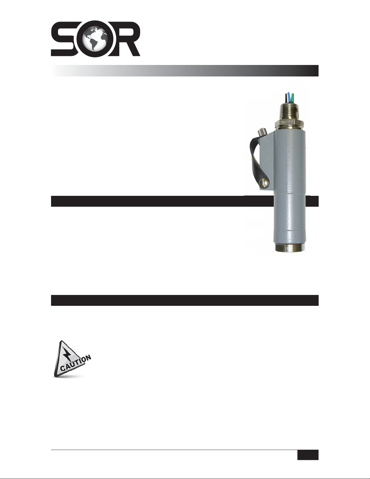
The static-o-ring type Pressure Switch is suitable for a wide variety
of process applications.
NOTE: If you suspect that a product is defective, contact the factory
or the SOR Representative in your area for a return authorization
number (RMA).
Pressure Switches for Fire Protective Signaling
.
ignaling
Installation
This product should only be installed by trained and competent personnel.
The pressure switch may be line mounted to either rigid process piping or
electrical conduit. The body of the pressure switch should be clamped in
the area between the set point adjustment protrusion and the pressure
port to a suitable member on applications when rigid process piping or
electrical conduit is not available.
rsonnel
iping or
ped in
sure
Process Connection
Use two wrenches when connecting process pipe: an 1-1/8 inch open-end wrench to hold
the hex port while connecting the process pipe; the other wrench to tighten the process
pipe or tube fitting.
When rigid process piping is used, it is important that no bending or torsional
forces be imposed on the pressure switch.
Design and specifications are subject to change without notice.
For latest revision, go to sorinc.com
Form 1296 (05.13) ©SOR Inc.
Registered Quality System to ISO 9001
1/4
Page 2
Electrical Connection
Ensure that wiring conforms to all applicable
local and national electrical codes and install
unit(s) according to relevant national and local
safety codes.
Use an 1-1/8 inch open-end wrench to hold
the hex on the electrical connection while
conduit or conduit fitting is being tightened.
Do not use a pipe wrench or strap wrench on the round body nor an open-end
wrench on the hex pressure port while tightening the conduit connection,
because the hermetically sealed switching element capsule has been precisely
positioned and locked during manufacture. Excessive force could overcome the
lock and cause movement which will adversely affect operation or render the
pressure switch inoperative. Should movement occur, factory calibration must
be performed in order to restore normal operation.
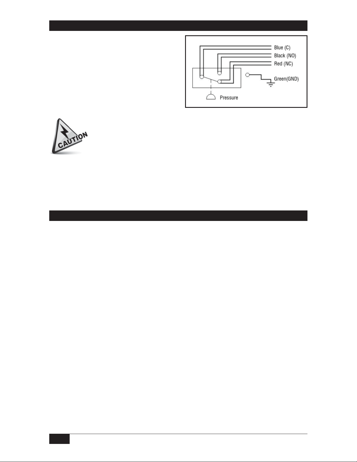
Electrical leads are in duplicate for wiring supervision and are marked NC (Normally Closed),
NO (Normally Open) and C (Common).
Calibration
The Pressure Switches are field adjustable across the entire cataloged range for a particular
piston/spring combination. Field adjustable models have a set point adjustment under the
removable weathertight cap.
It is not necessary to disconnect the electrical power, since the electrical switching element is
inside the hermetically sealed, explosion-proof capsule, thereby maintaining explosion-proof
integrity.
Remove the knurled weathertight cap.
Use an 1/8 inch hex (Allen type) wrench to turn the adjusting screw to achieve the
desired set point. Turn the adjusting screw clockwise (in) to increase set point; turn the
adjusting screw counterclockwise (out) to decrease set point. Use an external pressure
measuring device to accurately calibrate set points.
After the set point has been calibrated, replace the weathertight sealing cap tightly to
ensure the weathertight integrity of the device.
SOR discourages field modifications, change-out of wetted parts or repair. It is recommended
that products be returned to SOR for inspection and necessary repair work. Any field work
should be performed by a qualified instrument technician with formal SOR procedures.
2/4
Form 1296 (05.13) ©SOR Inc.
Page 3

Dimensions
*156.6
6.17
76.2
3.00
INSTALLATION
CLEARANCE MIN
FACTORY SEALED LEADS
COLOR CODED & MARKED
457.2
MIN LENGTH
18.00
ELECT CONN
1/2 NPTM
28.7
HEX
1.13
WEATHERTIGHT
COVER SCREW
FLEXIBLE SEAL
RETAINER
EXTERNAL GROUND
BG, BH, & JH HOUSING
** HEX
Linear = mm/inches
Drawing 0090119
PROCESS
CONN SIZE
1/4 NPTF SHOWN
1/2 NPTF
9/16 SAE SHOWN
3/4 NPTM
* LENGTH
ADD
ADD
1,5,6,9
13.2
0.52
23.1
0.91
34.9
1.38
** HEX
** HEX
PROCESS
CONNECTION
Dimensions are for reference only.
Contact the factory for certified drawings
for a particular model number.
* LENGTH
2,3
14.0
ADD
0.55
24.1
ADD
0.95
14.0
ADD
0.55
N/A N/A
* LENGTH
56
18.3
ADD
0.72
N/A
** HEX
1,5,6,9,56
28.7
1.13
** HEX
2,3
28.7
1.13
38.1
1.50
28.7
1.13
Form 1296 (05.13) ©SOR Inc.
3/4
Page 4

Ordering Information
Part
Number
9013-297
9013-298 125V (1A) 30V (1A)
9013-299
9013-300 125V (1A) 30V (1A)
9013-301
9013-302 125V (1A) 30V (1A)
9013-303
9013-304 125V (1A) 30V (1A)
Adjustable
Range psi
500 - 4000 5000
200 - 1750
100 - 500
25 - 240 1500 2500
Overrange
psi
2500
Proof
6000
psi
AC Rating DC Rating
250V (11A) 125V (0.5A), 30V (5A)
250V (11A) 125V (0.5A), 30V (5A)
250V (11A) 125V (0.5A), 30V (5A)
250V (11A) 125V (0.5A), 30V (5A)
Electrical Rating
Printed in USA sorinc.com
14685 West 105th Street, Lenexa, KS 66215 913-888-2630 800-676-6794 USA Fax 913-888-0767
4/4
Registered Quality System to ISO 9001
Form 1296 (05.13) ©SOR Inc.
 Loading...