

Page 1

107
tallation, electrical connection, p
oes
Pressure Switches.
m
to
at actuates
nt. Low
ge spring
accomplished by
oint adjustment screw.
, contact the
for a retur
n
d only be
Differential Pressure Switch
General Instructions
These instructions provide information for installation, electrical connection, process
connection and calibration of 107 Differential Pressure Switches.
NOTE: If you suspect that a product is defective, contact the
®
factory or the SOR
authorization number (RMA). This product should only be
installed by trained and competent personnel.
Principle of Operation
Process pressure is sensed by a diaphragm
and piston assembly. The piston responds to
differential pressure and moves a shaft that actuates
(deactuates) an electrical switching element. Low
side pressure and a wetted adjustable range spring
oppose high side pressure. Calibration is accomplished by
adjusting the range spring with the set point adjustment screw.
Representative in your area for a return
107EL
Application
The 107 Differential Pressure Switch is suited for draft range service as well as industrial air and
gas services which are compatible with the wetted parts and within nameplate specifications.
Contact the SOR representative in your area or the factory in Lenexa, Kansas for details.
Use care during installation not to inadvertently move the electrical switching
element or its housing. Movement of either could disturb the relative positions of
internal working parts and alter calibration or render the device inoperative.
Installation
The 107 is position sensitive. Mount the 107 so that the diaphragm is vertical (as shown
above). Non-vertical mounting positions will cause calibration scale error.
If condensation is expected within process piping, pressure ports should be located at 6
o’clock to prevent moisture accumulation within the instrument. If condensation is not
expected, the pressure ports can be positioned to any location as long as the diaphragm
remains vertical.
Securely mount the base plate bracket to flat surface using suitable bolts.
Design and specifications are subject to change without notice.
Form 492 (11.13) ©SOR Inc.
For latest revision, go to sorinc.com
Registered Quality System to ISO 9001
1/4
Page 2
Safety Integrity Level (SIL) Installation Requirements
The SOR pressure switches have been evaluated as Type-A safety related hardware.
To meet the necessary installation requirements for the SIL system, the following
information must be utilized:
Proof Test Interval shall be one year.
Units may only be installed for use in Low Demand Mode.
Products have a HFT (Hardware Fault Tolerance) of 0, and were evaluated in a
1oo1 (one out of one) configuration.
Form 1538 (03.12) ©2012 SOR Inc.
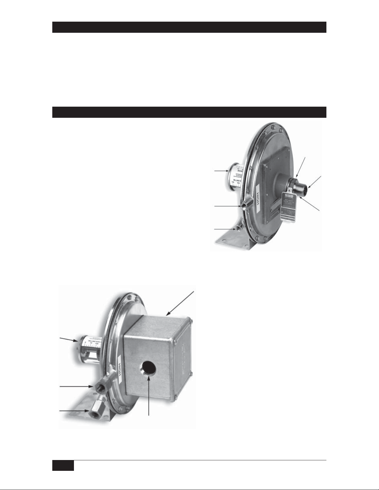
Process Connection
The high-pressure side (marked HIGH) and the low pressure
side (marked LOW) have 1/8” NPT(F) process connections
unless 1/4” NPT(F) adapters were specified.
Set point adjustment screw (not shown)
High side process connection
Low side process connection
Hermetically sealed switching element capsule
18 AWG wire leads (not shown)
1/2” NPT(M) electrical conduit connection
3/4” NPT(F) electrcial conduit connection
Weatherproof switching element housing
Hazardous Locations - 107EL
Ensure that wiring conforms to
all applicable local and national
electrical codes and install unit(s)
according to relevant national and
local safety codes.
Non-Hazardous Locations - 107AL
2/4
Form 492 (11.13) ©SOR Inc.
Page 3

Electrical Connection
107AL (weatherproof): Interrupt electrical power. Remove top cover plate.
Screw terminals are standard. Terminals are identified
C - Common, NO - Normally Open and NC - Normally Closed.
(Use terminal identification on sticker located on the floor of
the housing. Do not use identification on microswitch.)
107EL (explosion proof): Hermetically sealed switching element capsule has
”
18
C - Common, NO - Normally Open, NC - Normally Closed
and G - Ground (earth). (See below.)
Wire Lead Color Code
Units in hazardous locations-prior to removal from service, make sure
that the work area is declassi ed. Failure to do so could result in severe
personal injury or substantial property damage.
- 18 AWG wire leads color coded and marked
DPDT (2 SPDT)
SPDT
NO 1
LO
Differential Pressure
HI
LO
Differential Pressure
HI
Blue (C)
Red (NO)
Black (NC)
Yellow (C2)
Orange (NO2)
Brown (NC2)
Green (GND)
NO 2
Blue (C)
Red (NO)
Black (NC)
Green (GND)
See SOR Catalog 459 for reference dimension drawings. For certified dimension
drawings, contact the factory.
Form 492 (11.13) ©SOR Inc.
3/4
Page 4

Calibration
Normal Calibration: Turn set point adjustment screw to move spring guide plate
into alignment with desired set point on calibration scale.
Precise Calibration: Device calibrated without reference to calibration scale
and low side vented.
Test apparatus: Manometer
Variable pressure source
Test light or ohmmeter
Connect variable pressure source to manometer and high side pressure port.
Connect test light or ohmmeter to C-Common and NO - Normally Open switching
element contacts.
Raise pressure and note manometer reading when circuit closes.
Slowly drop pressure and note manometer reading when circuit opens.
Use a screwdriver to turn set point adjusting screw: counterclockwise to increase set
point, or clockwise to decrease set point.
Repeat steps 3, 4 and 5 until contacts change at desired increasing or decreasing
differential pressure set point.
Do not remove other covers or attempt to adjust other parts of the
mechanism. All have been precisely positioned at the factory and
should not be moved in the eld.
Printed in USA sorinc.com
14685 West 105th Street, Lenexa, KS 66215 913-888-2630 800-676-6794 USA Fax 913-888-0767
4/4
Registered Quality System to ISO 9001
Form 492 (11.13) ©SOR Inc.
 Loading...