

Page 1

B & J
Pressure Switches
General Instructions
These instructions provide information for the installation and field calibration of SOR
®
B & J Pressure Switches.
The pressure sensing element of the SOR B & J pressure switch is a force-balanced
piston-actuated assembly sealed by a flexible diaphragm and an o-ring that is static. The
only wetted parts in this arrangement are: the pressure port, the diaphragm and o-ring.
An optional welded pressure port and diaphragm assembly eliminates the o-ring. A wide
selection of wetted parts materials is available for compatibility with the process media.
Media pressure on the piston counteracts the force of the adjustable range spring, which
moves the piston shaft only a few thousandths of an inch to directly actuate the electrical
switching element.
NOTE: If you suspect that a product is defective, contact the factory or the SOR Representative
in your area for a return authorization number (RMA). This product should only be installed by
trained and competent personnel.
Installation
B & J pressure switches may be secured to bulkheads, panels or pipe stanchions with
suitable bolts.
Failure to mount the housing on a at mounting surface may result in torsional
forces on the housing that could cause false trips or render the pressure switch
inoperative.
Line mounting by either the process connection or the electrical conduit connection is
NOT recommended.
Table of Contents
Design and
specifications are
subject to change
without notice.
For latest revision, go to
www.sorinc.com
Installation .......................................1
SIL Installation ..................................2
Process Connection ............................2
Electrical Connection ...........................3
Calibration .......................................4
ATEX Marking Details ..........................4
Operation...................................... 5-7
Declaration of Conformity .....................8
Form 316 (01.13) ©SOR Inc.
Registered Quality System to ISO 9001
1/8
Page 2
Safety Integrity Level (SIL) Installation Requirements
The SOR pressure switches have been evaluated as Type-A safety related hardware.
To meet the necessary installation requirements for the SIL system, the following
information must be utilized:
Proof Test Interval shall be one year.
Units may only be installed for use in Low Demand Mode.
Products have a HFT (Hardware Fault Tolerance) of 0, and were evaluated in a
1oo1 (one out of one) configuration.
Form 1538 (03.12) ©2012 SOR Inc.
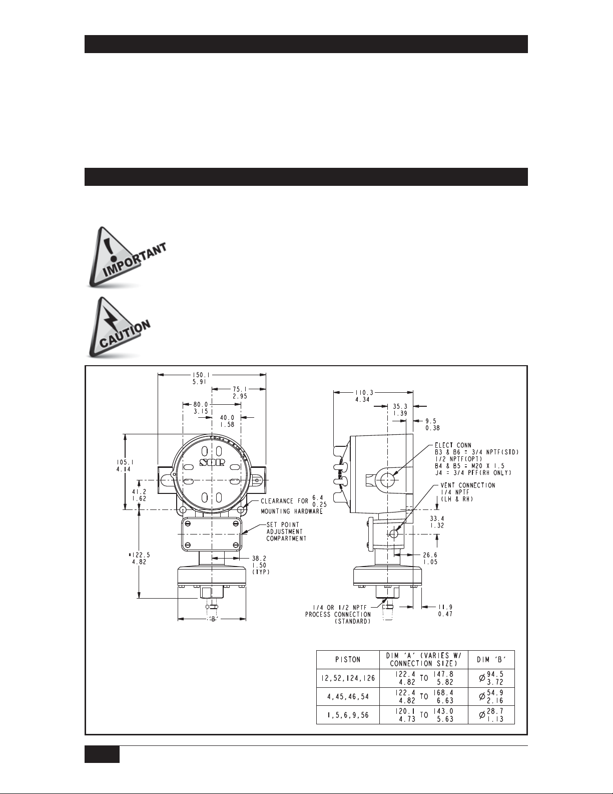
Process Connection
Securely connect the process line to the pressure connection using two wrenches; one to hold
the wrench flats on the pressure port, the other to tighten the process pipe or tube fitting.
Ensure that the process connection is tightened and positioned so
that bending and torsional forces imposed on the pressure switch are
minimal. Do not loosen the pressure port from the body or the body from
the housing, because leakage could result or the pressure switch could
be rendered inoperative.
One vent connection should be tted with a suitable breather to maintain
weathertight rating NEMA 4, 4X, IP65 or vented to a safe area. Piping
should be minimum 1/4” diameter and maximum 5 meters long (based
on process uid SG 1.0). The other vent connection may be plugged.
Linear = mm/inches
Drawing 0091417
Dimensions are for reference only.
Contact the factory
for certified drawings
for a particular model number.
2/8
Form 316 (01.13) ©SOR Inc.
Page 3
Electrical Connection
Ensure that wiring conforms to all applicable local and national electrical codes and install
unit(s) according to relevant national and local safety codes.
NOTE: For ATEX Certi ed Models: Electrical conduit connection threads may be of non-ISO thread
form. Check the product nametag for relevant thread form information before attempting to
connect to the electrical conduit connection. In the event a tting is used, check the adapter body
for thread size information.
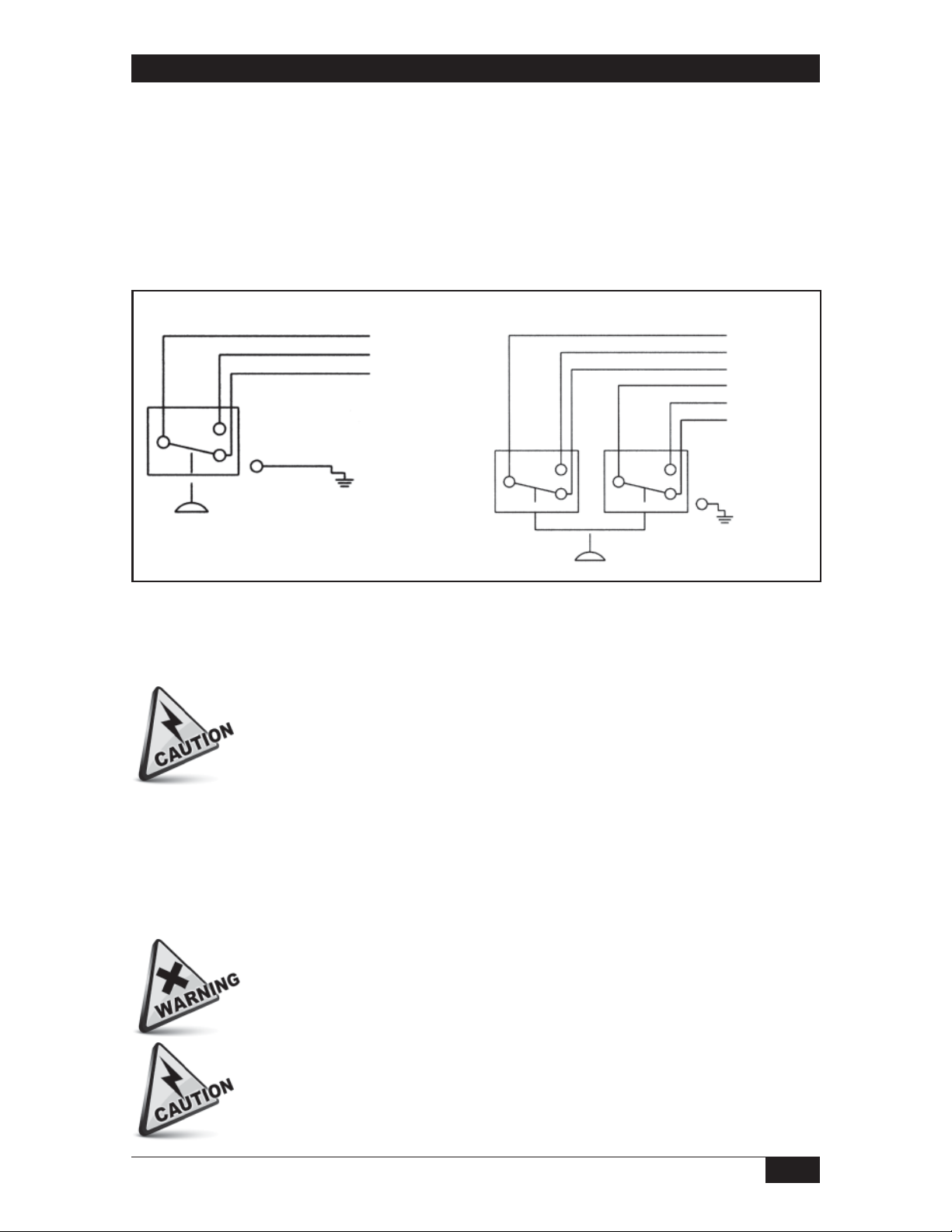
Standard electrical connection is a terminal block.
SPDT
Pressure
Blue (C)
Black (NO)
Red (NC)
Green (GND)
Blue (C)
DPDT (2-SPDT)
Pressure
Blue (C)
Black (NO)
Red (NC)
Yellow (C2)
Brown (NO2)
Orange (NC2)
NO2NO1
Green (GND)
B-series is 6-place compression type; J4 is 6-place screw type. The terminal block is marked:
Common (C), Normally Open (NO), Normally Closed (NC). If DPDT is specified, additional
markings are: Common 2 (C-2), Normally Open 2 (NO-2), and Normally Closed 2 (NC-2).
Overtravel has been preset at the factory, i.e. the switching element
assembly has been precisely positioned in the housing for optimum
performance. It normally should not be changed in the eld. Should
adjustment be necessary, factory approved procedures must be closely
followed. Any inadvertent movement or replacement in the eld will degrade
performance, void the warranty and could render the device inoperative,
unless factory approved procedures are followed.
NOTE: Internal primary equipment ground (earth) screw must be used for the equipment ground
connection and the external supplemental ground screw is provided for safety and compliance
with speci c code requirements.
The electrical compartment cover must remain sealed and the Allen locking
screw tightened at all times to prevent removal of the cover while the
pressure switch is in service.
Electrical power must be disconnected from explosion proof models before
the cover is removed. Failure to do so could result in severe personal injury
or substantial property damage.
Form 316 (01.13) ©SOR Inc.
3/8
Page 4

Calibration
Remove the set point adjustment compartment cover.
To increase the set point at which the switching element actuates, turn the hex adjusting
nut clockwise with a 3/4-inch open-end wrench.
Sight across the flat top of the adjusting nut to the calibration scale at the bottom of
the housing for an approximate set point. Use a 1/4% external pressure gauge to more
precisely calibrate the pressure switch.
Replace the set point adjustment compartment cover. The pressure switch can be
placed in service.
NOTE: The set point adjustment compartment is separate from the electrical compartment. The
set point may be changed without disconnecting electrical power.
ATEX Marking Information
For ATEX Certi ed Models
Manufacturer’s
Registered Trademark
Drawing 8513025
ATEX Listing
Information
Product Model
Identification
Thread Form
Information
Serial Number
(First Two Numbers
Indicate Year of Manufacture)
Special Conditions for Safe Use
To minimize the risk of electrostatic discharge, clean only with a damp cloth.
4/8
Form 316 (01.13) ©SOR Inc.
Page 5

Operation
For ATEX Certified Models
Maximum Surface Temperature
T6 Rating - 85
T5 Rating - 100
o
C
o
C
Regular Pressure
Piston-
Adjustable Range Overrange Proof
Spring
Designators
12 - 66 (0.6 to 2.5) [1.5 to 6.2]
12 - 614 (2.5 to 45) [6.2 to 110]
12 - 2 0.4 to 2.0 [30 to 140]
12 - 4 0.5 to 6.0 [35 to 415]
12 - 5 0.75 to 12 [50 to 830]
12 - 45 1 to 16 [70 to 1100]
4 - 2 2 to 8 [140 to 550]
4 - 4 2 to 25 0.14 to 1.7
4 - 5 3 to 50 0.2 to 3.5
4 - 45 4 to 75 0.3 to 5
6 - 2 7 to 30 0.5 to 2
psi (in. wc) bar [mbar] psi bar psi bar
200 14 400 28
750 50 1000 70
6 - 3 12 to 100 0.8 to 7
6 - 5 20 to 180 1.4 to 12
6 - 45 25 to 275 1.7 to 19
5 - 3 25 to 240 1.7 to 16
5 - 5 35 to 375 2.4 to 26
5 - 45 45 to 550 3.1 to 38
9 - 4 100 to 500 7 to 35
9 - 45 200 to 1750 14 to 120
1 - 45 500 to 4000 35 to 275 5000 340 6000 410
Form 316 (01.13) ©SOR Inc.
1500 100 2500 170
2500 170 6000 4109 - 5 200 to 1000 14 to 70
5/8
Page 6

Vacuum
Adjustable Range
Piston-
(Vacuum - 0 - Pressure)
Spring
Designators
52 - 116 (20 - 0 - 20) [50 - 0 - 50]
52 - 117 (40 - 0 - 40)
54 - 117 15 - 0 - 15 0.5 - 0 - 0.5
54 - 118 30 - 0 1.0 - 0
56 - 216 30 - 0 - 20 1.0 - 0 - 0.7
56 - 316 30 - 0 - 160 1.0 - 0 - 5.4
in. Hg (in.
wc)
bar [mbar] psi bar psi bar
Pivot Seal
[100 - 0 -
100]
Overrange Proof
200 14 400 28
750 50 1000 70
1500 100 2500 170
Piston-
Adjustable Range Overrange Proof
Spring
Designators
2 - 3 100 to 1900 7 to 130
3 - 45 1000 to 7000 70 to 480
psi bar psi bar psi bar
8000 550 10,000 7002 - 5 500 to 3000 35 to 210
6/8
Form 316 (01.13) ©SOR Inc.
Page 7

Designator AC Rating DC Rating Resistive
SPDT DPDT Volts Amps Volts Amps Volts Amps
K KK 250 15 - - - -
KA - 125 1 - - - -
J JJ 125 1 - - 30 1
G GG 250 15 125 0.5 - -
A AA 250 11 - - 30 5
L LL 250 15 125 0.5 - -
E EE 250 5 - - - -
C - 250 15 125 0.5 - -
S - 125 10 125
B BB 250 5 125 0.3 - -
Y YY 250 5 - - - -
W - 250 5 - - - -
N - 250 10 - - - -
T - 250 15 - - - -
H - 250 15 - - - -
AF AG 250 11 - - 30 5
EF EG 250 5 - - - -
JF JG 125 1 - - 30 1
1.5 min.
10.0 max.
--
Form 316 (01.13) ©SOR Inc.
7/8
Page 8

Declaration of Conformity
Form 1380 (08.12) ©2012 SOR Inc. (Printed in USA)
Product
Manufacturer
Date of Issue
We declare that the above
products conform to
the following specifications
and directives
Carries the marking
Reference document
ATEX Notified Body
Persons responsible
B Series Pressure and Temperature Switches
SOR Inc.
14685 West 105
th
Street
Lenexa, Kansas 66215-2003
United States of America
July 16, 2012
ATEX Directive (94/9/EC) Equipment Intended for use
in Potentially Explosive Atmospheres
EN 60079-0:2009
EN 60079-1:2007
II 2 G Ex d IIC T6 Gb
(Tamb = -40°C to +65°C) or T5 (Tamb = -40°C to +80°C)
EC-Type Examination Certificate
Baseefa02ATEX0252X
Issued May 7, 2003
Baseefa Ltd. (Notified Body No. 1180)
Rockhead Business Park, Staden Lane,
Buxton, Derbyshire SK17 9RZ
United Kingdom
Baseefa Customer Reference No. 1021
John J. Fortino (VP of Engineering)
John J. Fortino
14685 West 105th Street, Lenexa, KS 66215-2003
s53!s&!8
Engineered to Order with Off-the-Shelf Speed
EC Declaration
of Conformity
For ATEX Certi ed Models
Printed in USA sorinc.com
14685 West 105th Street, Lenexa, KS 66215 913-888-2630 800-676-6794 USA Fax 913-888-0767
8/8
Registered Quality System to ISO 9001
Form 316 (01.13) ©SOR Inc.
 Loading...