

Page 1
Dual Hi-Lo
Instructions
Pressure Switches
General Instructions
The pressure sensing elements are a pair of force-balanced,
piston-actuated assemblies sealed by flexible diaphragms and o-rings
that are static. The only wetted parts in this arrangement are the single
pressure port, two sensing assembly diaphragms and o-rings.
Media pressure on the area of the pistons counteracts the force of
the range spring (adjustable by the adjusting nuts),
which moves the piston shafts only a few
V1 Weathertight
Housing
thousandths of an inch to directly actuate
the electrical snap-action switching elements.
NOTE: If you suspect that a product is defective,
®
contact the factory or the SOR
your area for a return authorization number (RMA).
This product should only be installed by trained
and competent personnel.
Representative in
V2 Weathertight
Explosion Proof
Hermetically
Sealed
Installation
Dual Hi-Lo Pressure Switches may be secured to bulkheads, panels or pipe stanchions with
suitable bolts. When mounting the pressure switch to an irregular or uneven flat surface,
install rubber washers on the mounting bolts between the housing and the mounting surface.
Failure to place washers between the housing and the mounting surface may
result in torsional forces on the housing that could cause false trips or render
the pressure switch inoperative.
Failure to mount the housing on a at mounting surface may result in
torsional forces on the housing that could cause false trips or render the
pressure switch inoperative.
Line mounting by either the process connection or the electrical conduit connection is not
recommended.
Safety Integrity Level (SIL) Installation Requirements
The SOR pressure switches have been evaluated as Type-A safety related hardware.
To meet the necessary installation requirements for the SIL system, the following
information must be utilized:
Proof Test Interval shall be one year.
Units may only be installed for use in Low Demand Mode.
Products have a HFT (Hardware Fault Tolerance) of 0, and were evaluated in a
1oo1 (one out of one) configuration.
Design and specifications are subject to change without notice.
For latest revision, go to www.sorinc.com
Form 1538 (03.12) ©2012 SOR Inc.
Form 248 (04.13) ©SOR Inc.
Registered Quality System to ISO 9001
1/4
Page 2
Process Connection
Securely connect the process line to the pressure port using two wrenches; one to hold the
hexagonal flats on the pressure port, the other to tighten the process pipe or tube fitting.
Ensure that the process connection is tightened and positioned so that
bending and torsional forces imposed on the pressure switch are minimal. DO NOT loosen the pressure port from the body, because leakage
could result or the pressure switch could be rendered inoperative.
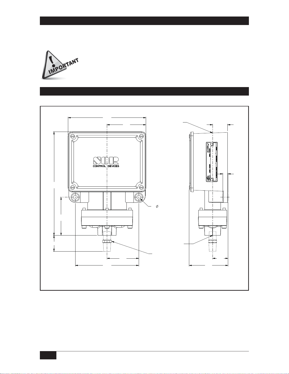
Dimensions
V1 WEATHERTIGHT
139.9
5.51
70.0
2.75
ELECTRICAL
CONNECTION
3/4 NPTF STD
1/2 NPTF OPT
M20 X 1.5 F OPT
27.0
1.06
*186.2
7.33
*68.6
2.70
A
Linear = mm/inches
Drawing 0090236
114.3
4.50
57.2
2.25
2X
7.1
0.28
MOUNTING
HOLES
PROCESS
CONNECTION
1/4 OR 1/2 NPTM
PROCESS CONNECTION
OPTIONAL
70.0
2.76
27.8
1.09
9.5
0.38
2/4
Form 248 (04.13) ©SOR Inc.
Page 3
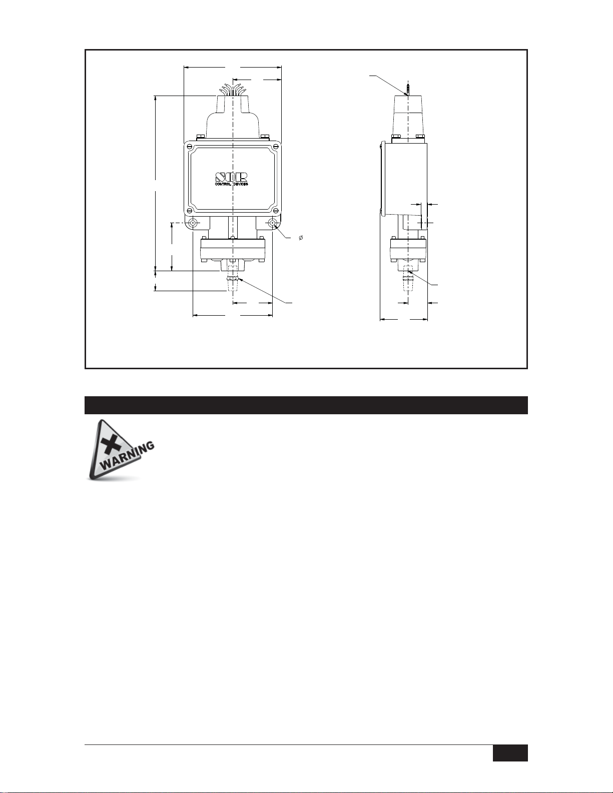
F
V2 EXPLOSION PROOF, HERMETICALLY SEALED
139.9
*251.2
9.89
*68.6
2.70
5.51
69.5
2.74
2X
7.1
0.28
MOUNTING
HOLES
ELECTRICAL
CONNECTION
3/4 NPTF STD
1/2 NPTF OPT
FACTORY SEALED
WIRE LEADS
9.5
0.38
A
Linear = mm/inches
Drawing 0090281
114.3
4.50
57.2
2.25
1/4 OR 1/2 NPTM
PROCESS CONNECTION
OPTIONAL
69.9
2.75
Dimensions are for reference only. Contact the factory for
certified drawings for a particular model number.
27.8
1.09
1/4 OR 1/2 NPT
PROCESS
CONNECTION
Electrical Connection
Units in hazardous locations— Prior to removal from service, make sure
that the work area is declassi ed. Failure to do so could result in severe
personal injury or substantial property damage.
Ensure that wiring conforms to all applicable local and national electrical codes and install
unit(s) according to relevant national and local safety codes.
V1 WEATHERTIGHT Common Normally Open Normally Closed
SPDT: Screw terminal block with marked insulation. Left and right positions.
No. 1 (Left side) C1 NO1 NC1
No. 2 (Right side) C2 NO2 NC2
2-SPDT (DPDT): Left and right positions
Nos. 1 & 2 (Left side) C1 NO1 NC1
C2 NO2 NC2
Nos. 3 & 4 (Right side) C3 NO3 NC3
C4 NO4 NC4
Form 248 (04.13) ©SOR Inc.
3/4
Page 4

“V2 EXPLOSION PROOF 18” 18 AWG color-coded and marked wire leads
with 3/4” NPT (F) conduit connection.
Common Normally Open Normally Closed
SPDT
No. 1 (Left side) C1 Blue NO1 Black NC1 Red
No. 2 (Right side) C2 Blue NO2 Black NC2 Red
2-SPDT (DPDT)
Nos. 1 & 2 (Left side) C1 Blue NO1 Black NC1 Red
C2 Yellow NO2 Brown NC2 Orange
Nos. 3 & 4 (Right side) C3 Blue NO3 Black NC3 Red
C4 Yellow NO4 Brown NC4 Orange
GR - Ground (Earth) Green wire connected to each hermetically sealed switching
element capsule.
NOTE: Transpose NO and NC on vacuum switches when set points are in the vacuum range.
Overtravel has been preset at the factory, i.e. the switching element assembly has
been precisely positioned in the housing for optimum performance. It normally
should not be changed in the eld. Should adjustment be necessary, factory
approved procedures must be closely followed. Any inadvertent movement or
replacement in the eld will degrade performance, void the warranty and could
render the device inoperative.
Calibration
Remove the housing cover.
To increase the set point at which the No. 1 (left side) switching element(s) actuates,
turn the hex adjusting nut clockwise with a 3/4-inch open-end wrench.
Sight across the flat top of the adjusting nut to the calibration scale at the bottom of
the housing for an approximate set point. Use a 1/4% external pressure gauge to more
precisely calibrate the pressure switch.
Repeat steps and for the No. 2 (right side) set point. There is no interaction, so it
is not critical whether the left or right side is set first.
Replace the housing cover. The pressure switch can be placed in service.
Printed in USA www.sorinc.com
14685 West 105th Street, Lenexa, KS 66215 913-888-2630 800-676-6794 USA Fax 913-888-0767
4/4
Registered Quality System to ISO 9001
Form 248 (04.13) ©SOR Inc.
 Loading...