

Page 1
Adjustable Dead Band
Pressure Switches
General Instructions
These instructions provide information for installation, process
®
and electrical connections and field calibration of SOR
Dead Band Pressure Switches.
The pressure sensing elements are a pair of force-balanced, pistonactuated assemblies sealed by flexible diaphragms and o-rings that
are static. The only wetted parts in this arrangement are the single
pressure port, two sensing assembly diaphragms and o-rings.
Adjustable
Media pressure on the area of the pistons counteracts the force of the
he
range springs (adjustable by the adjusting nuts), which moves the piston
shafts only a few thousandths of an inch to operate the lever assembly which actuates and
deactuates the electrical switching element.
NOTE: If you suspect that a product is defective, contact the factory or the SOR Representative
in your area for a return authorization number (RMA). This product should only be installed by
trained and competent personnel.
Installation
Adjustable Dead Band Pressure Switches may be secured to bulkheads, panels or pipe
stanchions with suitable bolts. When mounting the pressure switch to an irregular or
uneven flat surface, install rubber washers on the mounting bolts between the housing and
the mounting surface.
Line mounting by either the process connection or the electrical conduit connection is not
recommended.
Failure to place washers between the housing and the mounting surface
may result in torsional forces on the housing that could cause false trips
or render the pressure switch inoperative.
Failure to mount the housing on a at mounting surface may result in
torsional forces on the housing that could cause false trips or render the
pressure switch inoperative.
Design and specifications are subject to change without notice.
Form 466 (05.13) ©SOR Inc.
For latest revision, go to www.sorinc.com
Registered Quality System to ISO 9001
1/4
Page 2
Safety Integrity Level (SIL) Installation Requirements
The SOR pressure switches have been evaluated as Type-A safety related hardware.
To meet the necessary installation requirements for the SIL system, the following
information must be utilized:
Proof Test Interval shall be one year.
Units may only be installed for use in Low Demand Mode.
Products have a HFT (Hardware Fault Tolerance) of 0, and were evaluated in a
1oo1 (one out of one) configuration.
Form 1538 (03.12) ©2012 SOR Inc.
Process Connection
Securely connect the process line to the pressure port using two wrenches: one to hold the
hexagonal flats on the pressure port, the other to tighten the process pipe or tube fitting.
Ensure that the process connection is tightened and positioned so that
any binding and torsional forces imposed on the pressure switch are
minimal. Do not loosen the pressure port from the body because leakage
could result or the pressure switch could be rendered inoperative.
Electrical Connection
Ensure that wiring conforms to all applicable local and national electrical codes and install
unit(s) according to relevant national and local safety codes.
V1 – Weathertight
Common Normally Open Normally Closed
C1 NO1 NC1
V3 – Explosion proof
capsule has 18” - 18 AWG wire leads color coded and marked.
Common Normally Open Normally Closed
C1 - Blue NO1 - Black NC1 - Red
C2 - Yellow NO2 - Brown NC2 - Orange
GR - Ground (earth) green wire connected to each hermetically sealed switching element capsule.
SPDT: Screw terminal block with marked insulation.
DPDT (2-SPDT): Hermetically sealed switching element
Calibration
Remove the housing cover.
Connect a suitable variable pressure source with a calibrated reference gauge to the
pressure port. Connect an ohmmeter or test lamp across the switching element contact
terminals to monitor contact continuity. Use a 3/4” open-end wrench to turn the
adjusting nuts.
Slowly increase pressure to the pressure port. The continuity tester will indicate that
the contacts have changed state when increasing set point is reached. Note pressure
at increasing set point. If increasing set point is too low, turn the left adjusting nut
clockwise to raise the increasing set point. If increasing set point is too high, turn the
left adjusting nut counterclockwise to lower the increasing set point.
2/4
Form 466 (05.13) ©SOR Inc.
Page 3

Slowly decrease pressure to the pressure port. The continuity tester will indicate that
contacts have changed state when decreasing set point is reached. Note pressure at
decreasing set point.If the decreasing set point is too low, turn the right adjusting nut
clockwise to raise the decreasing set point. If the decreasing set point is too high, turn
the right adjusting nut counterclockwise to lower the decreasing set point. The left
adjusting nut must always be lower than the right adjusting nut when calibration is
complete.
Repeat Steps 3 and 4 until desired set points are obtained. If the pressure switch fails
to respond to pressure change during calibration, increasing/decreasing set points
may be too close together. See Form 281 for minimum/maximum dead band
capabilities. Replace the housing cover.
Overtravel has been preset at the factory. The 3/16” overtravel adjustment
screw on the lever assembly has been precisely positioned for optimum
performance. Any inadvertent movement could render the device inoperative
and void the warranty.
Increasing Set
Point Adjustment
To raise the increasing set
point, turn the left adjust-
ing nut clockwise. To lower
the increasing set point,
turn the left adjusting nut
counterclockwise.
The left adjusting nut must always be lower than the right adjusting nut when
calibration is complete.
Principle of Operation
Actuation
Decreasing
Set Point Adjustment
To raise the decreasing
set point, turn the right
adjusting nut clockwise.
To lower the decreasing
set point, turn the right
adjusting nut counterclockwise.
Deactuation
No pressure applied.
Electrical switching
element is deactuated.
Pressure greater
than decreasing set
point but less than
increasing
set point: Electrical
switching element
remains deactuated.
Piston movement exaggerated for clarity in drawings above.
Form 466 (05.13) ©SOR Inc.
Pressure equal to or
greater than increasing
set point: Electrical
switching element is
actuated.
Pressure less than
increasing set point
but greater than
decreasing set point:
Electrical switching
element remains
actuated.
Pressure equal to or
less than decreasing
set point: Electrical
switching element is
deactuated.
3/4
Page 4
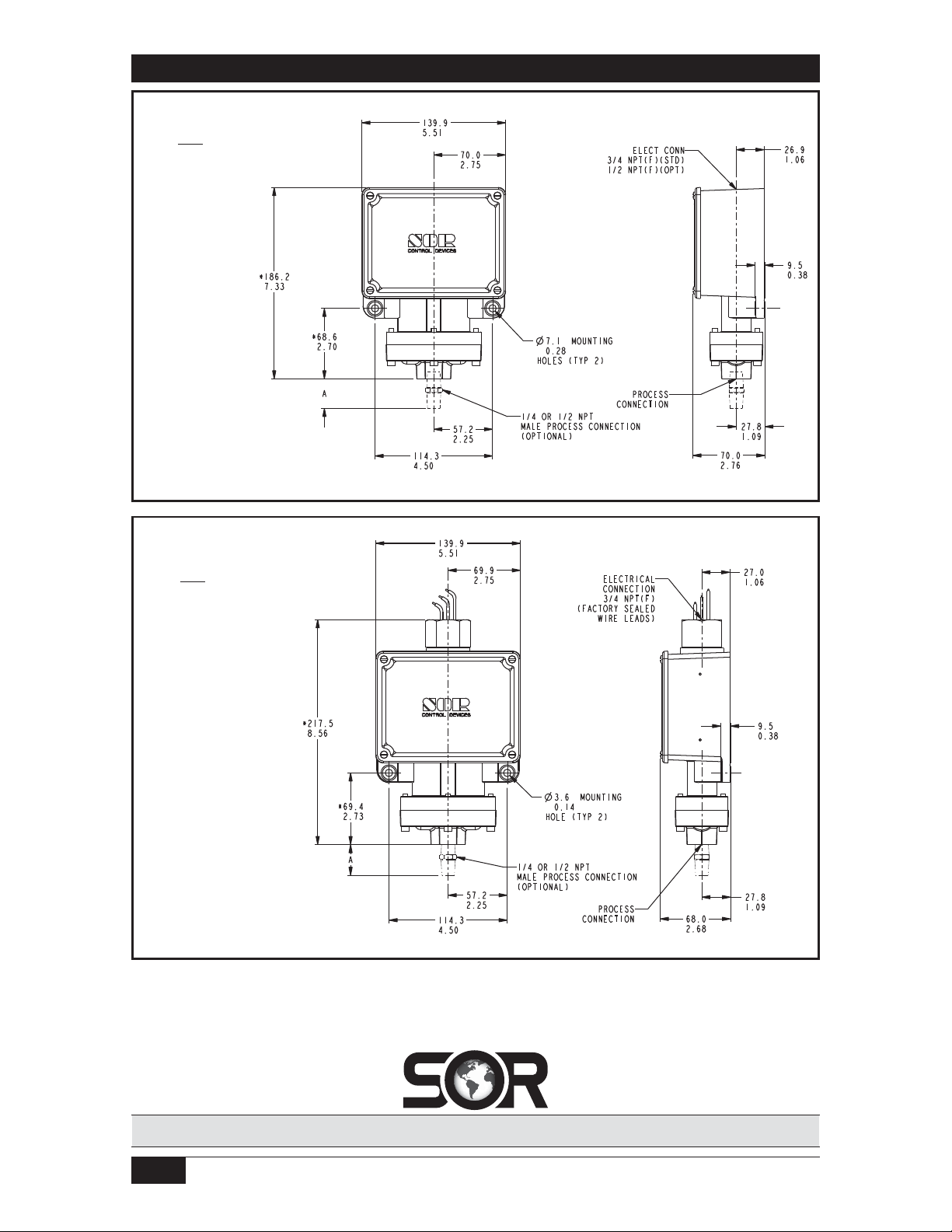
Dimensions
V1 Housing
6.4
*Add
Linear = mm/inches
Drawing 0090236
for non-aluminum ports.
0.25
V3 Housing
6.4
*Add
Linear = mm/inches
Drawing 0090325
for non-aluminum ports.
0.25
Dimensions are for reference only. Contact the factory
for certified drawings for a particular model number.
Printed in USA www.sorinc.com
14685 West 105th Street, Lenexa, KS 66215 913-888-2630 800-676-6794 USA Fax 913-888-0767
4/4
Registered Quality System to ISO 9001
Form 466 (05.13) ©SOR Inc.
 Loading...