

Page 1
534HS
v
.
Instructions
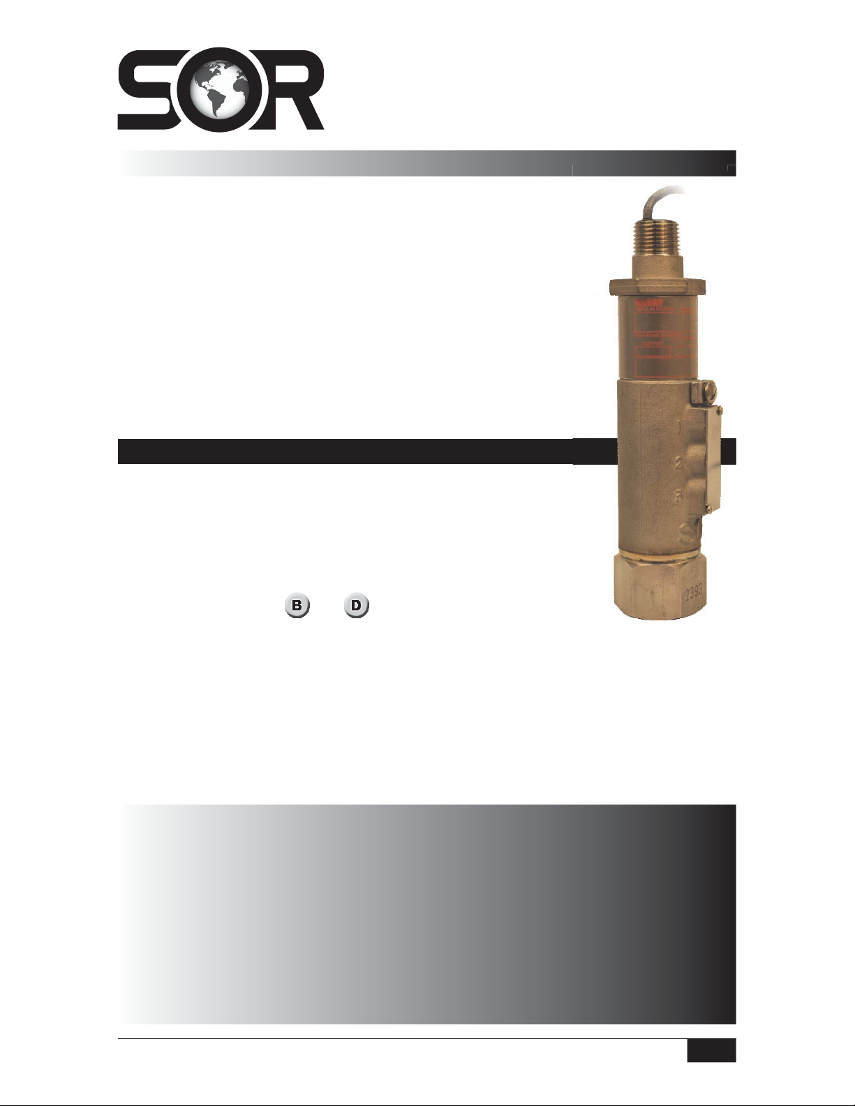
Pressure Transmitter
General Instructions
These instructions provide information for installation, process connection,
®
electrical connection and field calibration of SOR
Transmitters. The 534HS Pressure Transmitter consists of a field proven
thin film pressure transducer and a reliable electronic circuit. The
housing features external adjustments and stainless steel construction.
The 534HS is capable of powering long cable lengths. See Formulas
for maximum loop resistance formulas.
NOTE: This instrument is non-repairable. If you suspect that it is defective,
contact the factory or the SOR representative in your area for a return
authorization number.
534HS Pressure
ction,
en
n
e,
Installation
Ensure that wiring conforms to all applicable local and national
electrical codes and install unit(s) according to relevant national
and local safety codes.
Normally, line mounting provides adequate support for the instrument.
When the installation is complete, the external adjustments must be
accessible. (See Figures
connection or the electrical connection will be made first.
and
) Determine whether the process
nt.
e
ss
Making the Process Connection First
The process connection is threaded onto a fitting within an adequately supported process
piping system. Use two open end wrenches when connecting the pressure port to a
NOTE: If you suspect that a product is defective, contact the factory or the SOR Representative
in your area for a return authorization number (RMA). This product should only be installed by
trained and competent personnel.
Table of Contents
Design and
specifications are
subject to change
without notice.
For latest revision, go to
www.sorinc.com
Form 953 (03.13) ©SOR Inc.
Installation .......................................1
Wiring 534HS-TN ...............................2
Calibration .......................................2
Dimensions ......................................4
Wiring 534HS-VN ...............................4
Calibration .......................................5
Dimensions ......................................7
Control Drawings ...........................8-10
Registered Quality System to ISO 9001
1/12
Page 2
process piping system: one wrench to hold the hex flats of the pressure connection, the
other to tighten the process fitting. Electrical connection may be rigid or flexible conduit.
Making the Electrical Connection First
The electrical connection may be installed on an adequately supported rigid conduit
system. Use suitable locknuts (not provided) when mounting the instrument to an
unthreaded (knockout) hole. Process connection pipe or tubing may be rigid or flexible.
Securely connect the conduit pipe or fitting by holding the hex on the electrical connection
while tightening.
Unit in Hazardous Locations – Prior to removal from service, make sure
that the work area is declassi ed. Failure to do so could result in severe
personal injury or substantial property damage.
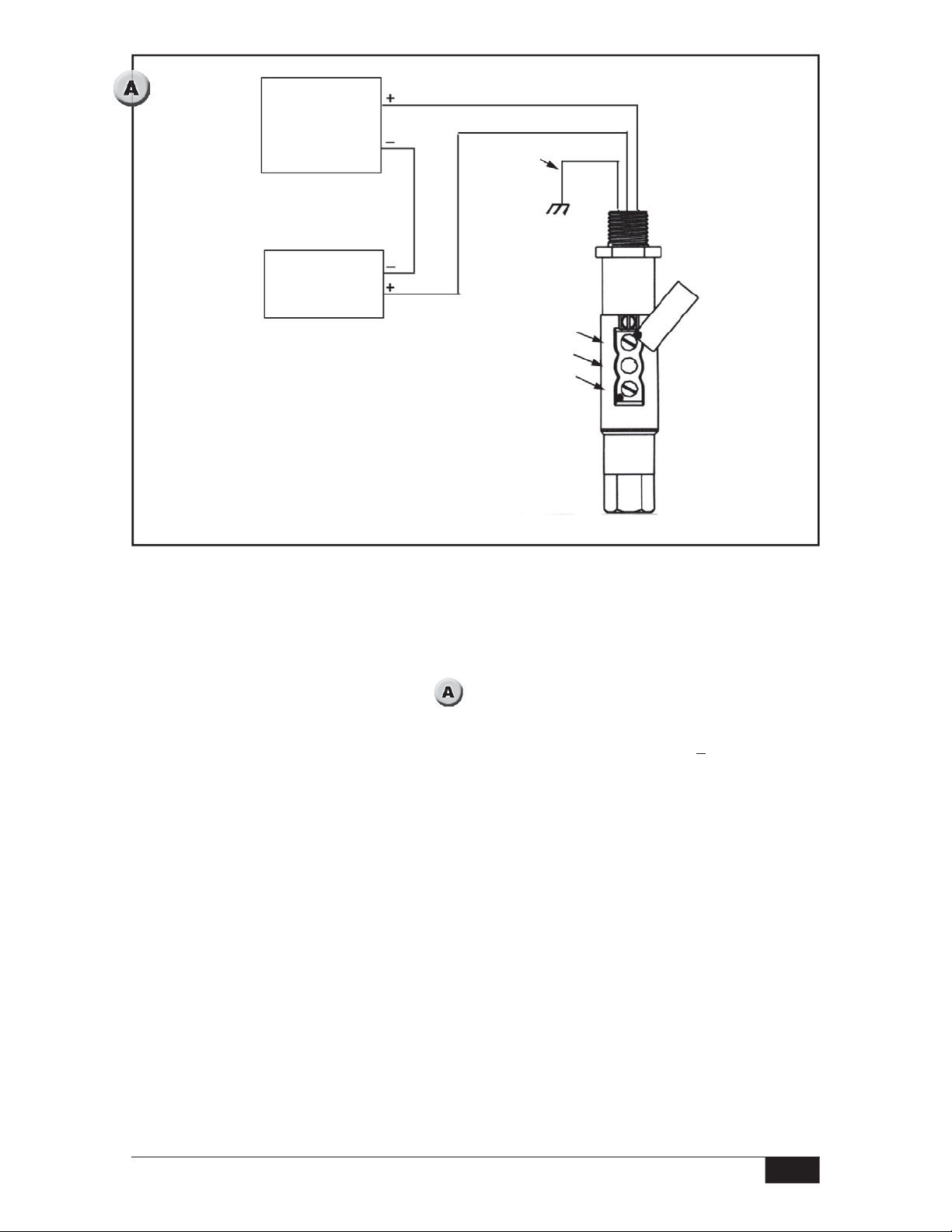
Wiring 534HS - TN
Three 18” flying leads are provided for connection to a terminal strip within a cabinet or a
splice within an outlet box:
Red (+)
Black (–)
Case ground (bare wire) should be connected to earth ground.
Formula for determining
maximum loop resistance:
Loop Voltage: 11 to 30 VDC; Output: 4 to 20 mA
}
V
Supply
RL (Max) =
- 11V
Calibration
Two calibration screws (zero and span) are located underneath the adjustment cover. (See
) Loosen the cover screws slightly (do not remove) and rotate the cover to reveal the
adjustment screws.
Numbers on the enclosure identify the adjustment screws: 1, 2 and 3.
Adjustment #1: Zero
Adjustment #2: Not used
Adjustment #3: Span
Unless specified otherwise, the transmitter is factory calibrated to 4 mA @ 0 psi and 20 mA
at the upper limit of the adjustable range specified on the nameplate.
Calibration Procedure
The zero and span calibration procedure should be performed under ambient process
temperature conditions.
2/12
Form 953 (03.13) ©SOR Inc.
Page 3
Power
Supply
11 - 30 VDC
Case
Ground
Red
Black
Bare
milliammeter
20 mA
4 -
Zero
Not Used
Span
A pressure source with a calibrated reference gage, a milliammeter and a DC voltage supply
are required. Note the adjustable range on the instrument nameplate. For both zero and span
adjustments, turn the adjustment screw clockwise to increase, counterclockwise to decrease.
Connect the transmitter as shown in . Case ground must be connected to earth
ground to ensure EMI/RFI protection.
Apply pressure at which 4 mA output is desired. (Zero may be adjusted +10% of the
upper range limit.)
When zero is elevated above 0 psi, maintain 80% of the range of the transmitter range
between the 4 mA and 20 mA points.
With pressure source steady at the desired zero level, rotate the zero adjustment (#1)
for a 4 mA indication on the milliammeter.
Apply pressure at which 20 mA output is desired. Span may be adjusted from 20 to
100% of the upper range limit. (Maximum turndown is 5:1.)
With pressure source steady at the desired span level, rotate the span adjustment (#3)
for a 20 mA indication on the milliammeter.
Repeat Steps 2 through 6 as needed if offsetting 4 mA from the normal zero point.
If interaction occurs, turn zero and span 15 turns counterclockwise. Repeat Steps 2
through 7 above.
Form 953 (03.13) ©SOR Inc.
3/12
Page 4
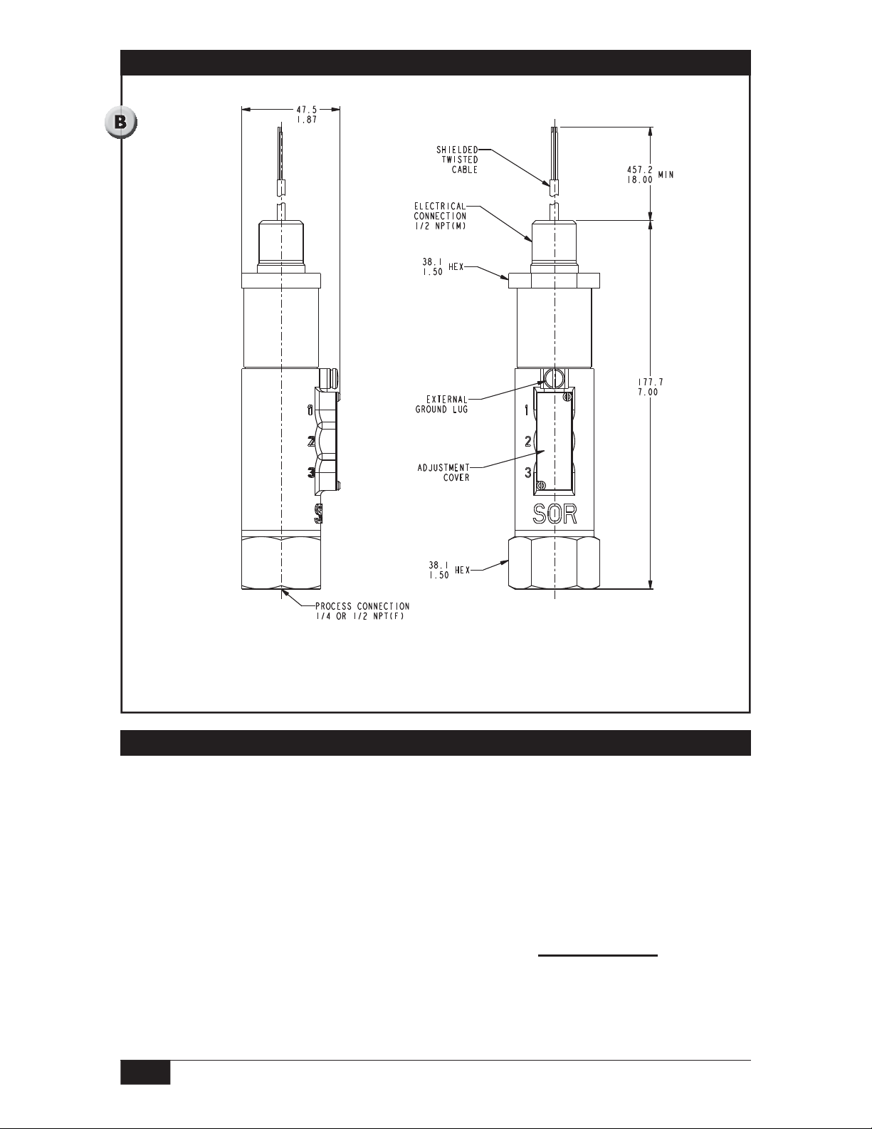
Dimensions
Linear = mm/inches
Drawing 0091119
Dimensions are for reference only.
Contact the factory for certified drawings for a particular model number.
Wiring 534HS-VN
Three screw terminals and center ground are provided for electrical connection,
labeled as follows:
+ 11-30 VDC + Power Connection
– Power supply ground
1-5 VDC Output
GND Case ground should be connected to earth ground.
Formula for determining
maximum loop resistance:
RL (Max) =
V
Supply
- 16V
4/12
Form 953 (03.13) ©SOR Inc.
Page 5

Calibration
Two calibration screws (zero and span) are located underneath the adjustment cover. (See
) Loosen the cover screws slightly (do not remove) and rotate the cover to reveal the
adjustment screws.
Numbers on the enclosure identify the adjustment screws: 1, 2 and 3.
Adjustment #1: Zero
Adjustment #2: Not used
Adjustment #3: Span
Unless specified otherwise, the transmitter is factory calibrated to 1 VDC @ 0 psi and 5
VDC at the upper limit of the adjustable range specified on the nameplate.
Calibration Procedure
The zero and span calibration procedure should be performed under ambient process
temperature conditions.
A pressure source with a calibrated reference gage, a voltmeter and a DC voltage supply
are required. Note the adjustable range on the instrument nameplate. For both zero and
span adjustments, turn the adjustment screw clockwise to increase, counterclockwise to
decrease.
Connect the transmitter as shown in Figure . Case ground must be connected to
earth ground to ensure EMI/RFI protection.
Apply pressure at which 1 VDC output is desired. (Zero may be adjusted up to +10% of
the upper range limit.)
When zero is elevated above 0 psi, maintain 80% of the transmitter range between the 1
VDC and 5 VDC points.
With pressure source steady at the desired zero level, rotate the zero adjustment (#1)
for a 1 VDC indication on the voltmeter.
Apply pressure at which 5 VDC output is desired. Span may be adjusted from 20 to
100% of the upper range limit. (Maximum turndown is 5:1.)
With pressure source steady at the desired span level, rotate the span adjustment (#3)
for a 5 VDC indication on the voltmeter.
Repeat Steps 2 through 6 as needed if offsetting 1 VDC from the normal zero point.
If interaction occurs, turn zero and span 15 turns counterclockwise. Repeat Steps 2
through 7 above.
Form 953 (03.13) ©SOR Inc.
5/12
Page 6

Voltmeter
1 TO 5 VDC
100K ohms min.
1-5 Volt
Terminal with
respect to
negative
Case Ground
Power
Supply
11-30 VDC
Terminals show
with transmitter
at 6 o’clock
6/12
Form 953 (03.13) ©SOR Inc.
Page 7

Dimensions
Linear = mm/inches
Drawing 0091124
Dimensions are for reference only.
Contact the factory for certified drawings for a particular model number.
Form 953 (03.13) ©SOR Inc.
7/12
Page 8

Control Drawing
8/12
Form 953 (03.13) ©SOR Inc.
Page 9

Control Drawing
Form 953 (03.13) ©SOR Inc.
9/12
Page 10

Control Drawing
10/12
Form 953 (03.13) ©SOR Inc.
Page 11

Form 953 (03.13) ©SOR Inc.
11/12
Page 12

Printed in USA www.sorinc.com
14685 West 105th Street, Lenexa, KS 66215 913-888-2630 800-676-6794 USA Fax 913-888-0767
12/12
Registered Quality System to ISO 9001
Form 953 (03.13) ©SOR Inc.
 Loading...