

Page 1
510IM
state
Immersible Transmitter
General Instructions
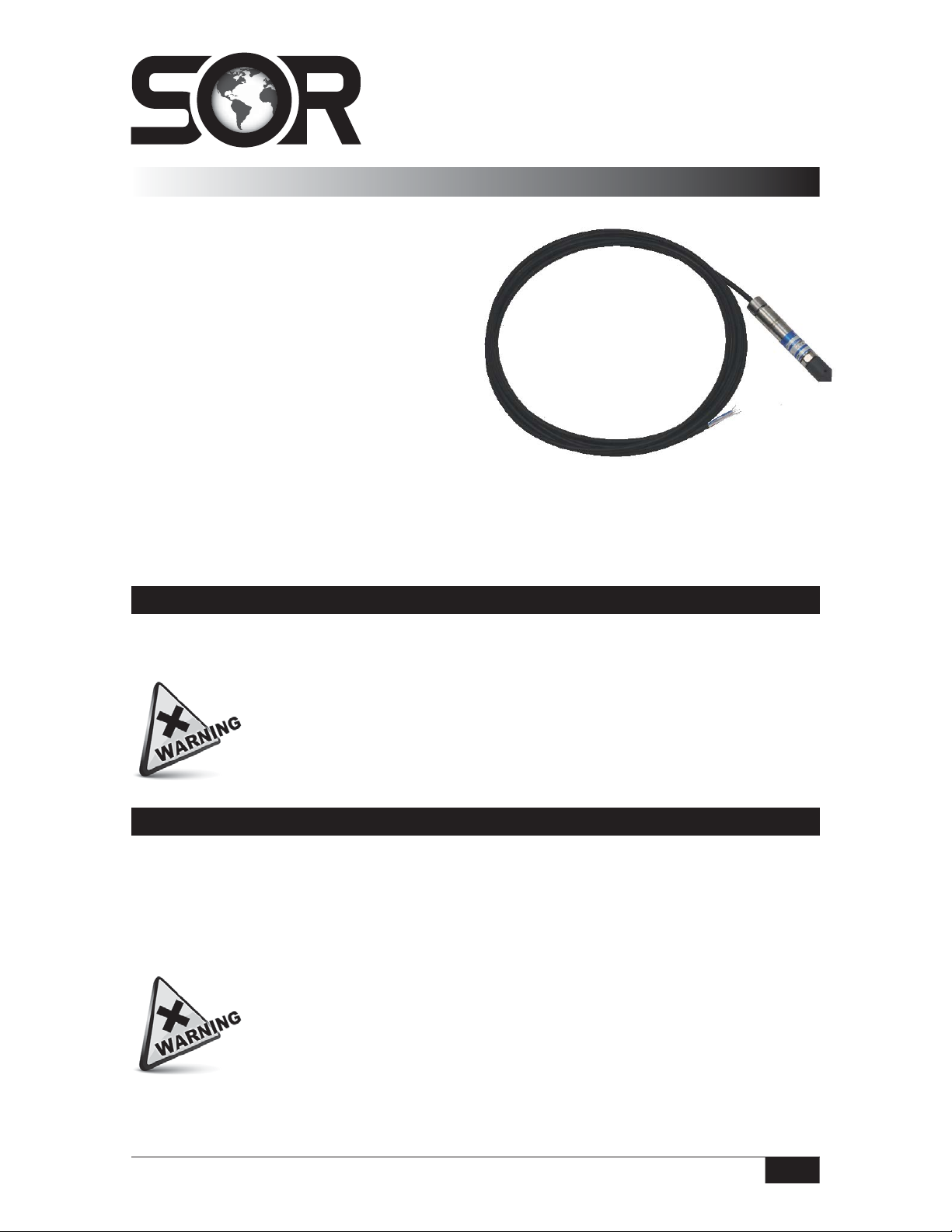
The 510IM Immersible Transmitter is a solid state
instrument designed for use in locations that are
subject to continuous or intermittent liquid
immersions. The instrument incorporates a
ceramic sensor to provide a quick, accurate
and reliable pressure measurement.
Electrical connection is made via a 20-gauge,
shielded waterproof cable that is vented above
the immersion level to reference atmospheric
pressure. The 1/4” NPT (M) process connection is
capable of self-supporting the transmitter.
NOTE: If you suspect that a product is defective, contact the factory or the SOR® Representative
in your area for a return authorization number (RMA). This product should only be installed by
trained and competent personnel.
are
,
e
ion is
Operation
Once the transmitter is installed and wired into a con trol or display loop, it is ready for use.
Before applying power, check that the supply polarity and excitation volt age are correct.
Do not twist the wires during installation or servicing the instrument as it
may break the integrity of the seal between the wires and the transmitter.
A failure of this nature is not covered by warranty.
Calibration
The transmitter is supplied factory calibrated and during normal use should not require
recalibration. If it is desired to verify calibration prior to installation, attach the transmitter
to a pressure source capable of adjustment throughout specified range. If outputs are not
within lim its at factory calibration conditions, 77°F (25°C), the device should be returned to
the factory.
Units in hazardous locations — Prior to removal from service, make sure
that the work area is declassi ed. Failure to do so could result in severe
personal injury or substantial property damage.
Design and specifications are subject to change without notice.
Form 1003 (03.13) ©SOR Inc.
For latest revision, go to www.sorinc.com
Registered Quality System to ISO 9001
1/4
Page 2
Installation
Before installing the transmitter, verify that the range stated on the transmitter label is
suitable for the pressure to be measured.
SOR 510IM submersible products should not be used in liquids known to
have or possibly contain chemical compounds that react with butyl rubber
or stainless steel.
The Series 510IM is designed to be self-supporting in any plane when rigidly mounted by
the pressure port (1/4” NPT process connection). Thread the transmitter in place using the
wrench flats provided.
The transmitter should not be used as a step!
When mounting the transmitter, care must be taken to prevent the cable bending through
a radius smaller than two inches. Failure to observe this precaution may result in damage
to the cable internal vent tube. This may give incorrect readings from the transmitter. Care
must be taken to prevent water entering or foreign objects block ing the vent tube, either of
which may result in a fault condition. Faults of this nature are not covered by the warranty.
Avoid mounting the transmitter near a heat source which is liable to overheat the
instrument or cause a temperature gradient across it. If this is unavoidable, introduce a
heat shield to deflect radiated heat and thus maintain the transmitter at a uniform
temperature within the specified limits.
Although the operating temperature of the transmitter extends to below 32°F, fluids must
not be allowed to freeze in the pressure port. Failure will occur due to the expansion of the
frozen fluid in the contained volume of the pressure port causing gross overpressurization.
A failure of this nature is not covered by warranty.
2/4
Form 1003 (03.13) ©SOR Inc.
Page 3

Wiring Details
Ensure that wiring conforms to all applicable local and national electrical codes and install
unit(s) according to relevant national and local safety codes.
The 510IM transmitter is designed to operate in a 2-wire, 4-20 mA system. A system of this
type requires that the measuring instrument alter the current consump tion of an electrical
circuit in proportion to pressure changes. The changes in current may be measured using
suitable instruments. Due to the design of the transmitter, it is unable to produce currents
less than approximately 3.3 mA. Should the transmitter output be “locked” at a figure of
this order, it is indicative of a fault and the system should be checked immediately.
Schematic diagrams for incorporation of the transmitter into a control or display loop are
shown below. The sup ply voltage at the transmitter terminals must be between 10 and
32 Vdc (IS option 28 VDC max). Polarity of the transmitter wiring is essential for proper
operation.
The transmitter will drive into a resistive
load, which is a function of the supply
voltage. This may be derived from the
Power
Supply
Red Wire
Blue Wire
White Wire
Transmitter
following formula:
Power
Supply
Millimeter
4 - 20 mA
Resistive
load
Case Ground
Red Wire
Blue Wire
White Wire
Case Ground
Transmitter
V
Supply
RL (Max) =
As noted earlier, the minimum current
the transmitter can supply is in the order
of 3.3 mA. If a reading of this nature is
obtained, it is usually indicative of a fault
condi tion, possibly due to damage to the
- 10V
transmitter caused by over pressurization
To Display or other
Process Instruments
or negative pressure being applied to the
transmitter.
The red wire is the positive power supply input, the blue wire is the negative power supply
input and white is case ground. Reverse connection will prevent the transmitter operating
due to its internal reverse polarity protection.
Form 1003 (03.13) ©SOR Inc.
3/4
Page 4

Dimensions
Dimensions are for reference only.
Contact the factory for certified drawings
for a particular model number.
Linear = mm/inches
Drawing 0091269
Servicing
This transmitter contains no user serviceable parts and cannot be repaired on site. It must
be returned to the factory. Disassembly of the instrument by unauthorized persons will
invalidate the warranty. If there is a risk of debris accumulating in the pressure port, it
should be very carefully cleaned.
Use of a sharp object such as a screwdriver or a high pressure spray to clean
the ceramic sensor could cause permanent damage!
Fault Conditions
If a malfunction occurs which is traced to the transmit ter, it should be removed for
inspection and test. If the transmitter has been subjected to excess pressure, vibra tion,
shock or extreme supply voltage (as in the case of a lightning strike), damage may be
indicated by a constant output, regardless of the applied pressure. Overpressure may also
cause high or unstable readings.
Blocked pressure ports or pipes may cause a similar symptom and should be rectified
before carrying out fur ther tests.
The transmitter can withstand pressure of 1-50% of its rated range without calibration
change. Pressures above this may cause irreparable damage to the sensor. Frequent
causes of such overpressures are high-transient pressures, which may not be easy to
detect during nor mal operation.
Printed in USA www.sorinc.com
14685 West 105th Street, Lenexa, KS 66215 913-888-2630 800-676-6794 USA Fax 913-888-0767
4/4
Registered Quality System to ISO 9001
Form 1003 (03.13) ©SOR Inc.
 Loading...