

Page 1
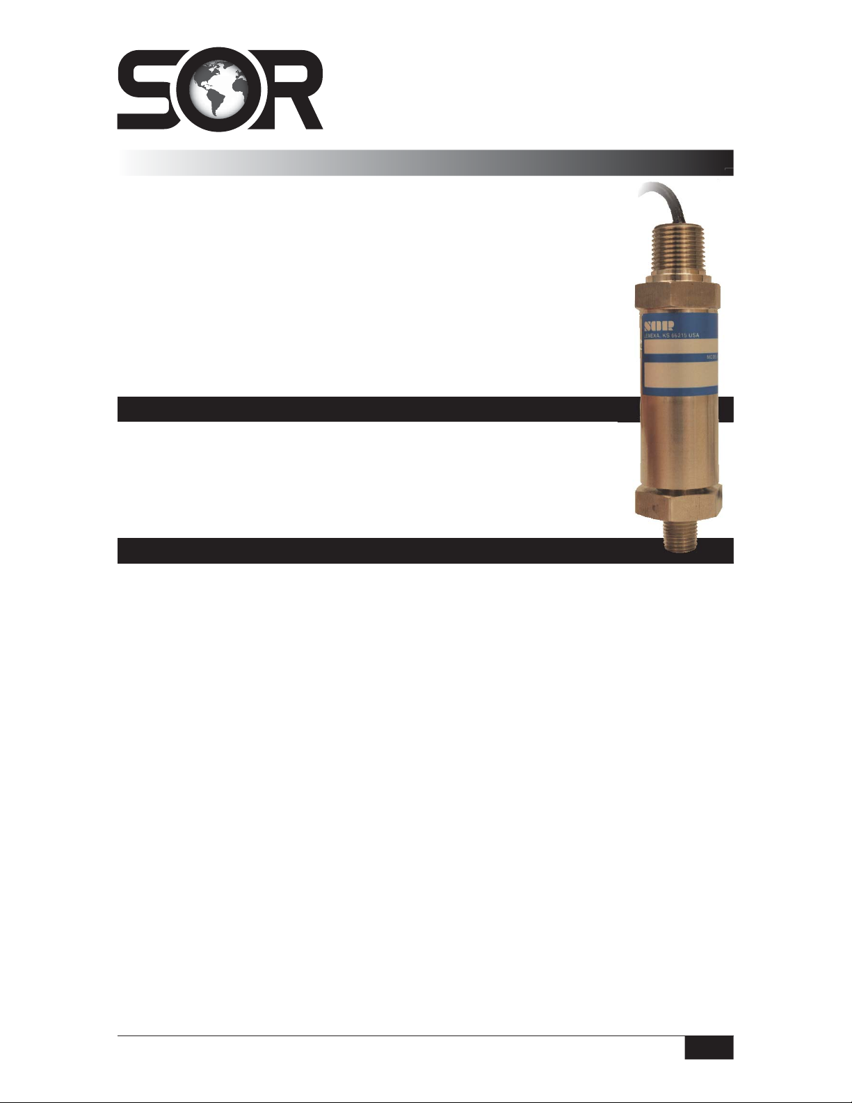
503FR Fixed Range
Instructions
Pressure Transmitter
General Instructions
The 503FR Fixed Range Pressure Transmitter is a loop powered, solid state
instrument designed for accurate and reliable pressure measurement. The
transmitter uses a high-performance ceramic sensor and a stainless steel
process connection for compatibility with many types of process fluids
requiring continuous monitoring.
NOTE: If you suspect that a product is defective, contact the factory or the
®
Representative in your area for a return authorization number (RMA).
SOR
This product should only be installed by trained and competent personnel.
Operation
Once the transmitter is installed and wired into a control or display loop,
it is ready for use. Before applying power, check that the polarity and
excitation voltage are correct.
Calibration
The transmitter is fixed range and supplied factory calibrated. If it is desired to verify
calibration prior to installation, attach the transmitter to a pressure source capable of
adjustment throughout a specified range. If outputs are not within limits at factory
o
calibration conditions, 77
F (25oC), the device should be returned to the factory.
Design and specifications are subject to change without notice.
Form 963 (03.13) ©SOR Inc.
For latest revision, go to www.sorinc.com
Registered Quality System to ISO 9001
1/4
Page 2

Installation
Ensure that wiring conforms to all applicable local and national electrical codes and install
unit(s) according to relevant national and local safety codes.
Before installing the transmitter, verify that the range stated on the transmitter label is
suitable for the pressure to be measured.
The transmitters are designed to be self-supporting in any plane when rigidly mounted by
the pressure port (1/4” NPT process connection). Thread the transmitter in place using the
wrench flats provided.
Avoid mounting the transmitter near a heat source which is liable to overheat the
instrument or cause a temperature gradient across it. If this is unavoidable, introduce
a heat shield to deflect radiated heat and thus maintain the transmitter at a uniform
temperature within the specified limits.
o
Although the operating temperature of the transmitter extends to below 32
not be allowed to freeze in the pressure port. Failure will occur due to the expansion of the
frozen fluid in the contained volume of the pressure port causing gross over-pressurization.
A failure of this nature is not covered by warranty.
F, fluids must
Wiring Details
The 503FR is designed for use in a 2-wire, 4-20 mA system. A system of this type
requires that the measuring instrument alter the current consumption of an electric circuit
in proportion to pressure changes. The changes in current may be measured using suitable
instruments. Due to the design of the transmitter, it is unable to produce currents less than
approximately 3.3 mA. Should the transmitter output be “locked” at a figure of this order,
it is indicative of a fault and the system should be checked immediately.
Schematic diagrams for incorporation of the transmitter into a control or display loop are
shown below. The supply voltage at the transmitter terminals must be between 10 and 32
Vdc on std. units, and between 10 and 28 Vdc on intrinsically safe units. Polarity of the
transmitter wiring is essential for proper operation.
2/4
Form 963 (03.13) ©SOR Inc.
Page 3

Current Loop
Voltage Divider
Power
Supply
Power
Supply
+
_
Resistive
Load
Case Ground
To display or
other process instruments
+
_
Milliameter
4-20mA
Red Wire
Blue Wire
Green Wire
Red wire
Blue wire
Green wire
Case Ground
Transmitter
Transmitter
The transmitter will drive into a resistive load, which is a function of the supply voltage.
This may be derived from the following formula:
V
Supply
- 10V
RL (Max) =
As noted earlier, the minimum current the transmitter can supply is in the order of 3.3 mA.
If a reading of this nature is obtained, it is usually indicative of a fault condition, possibly
due to damage to the transmitter caused by over-pressurization or negative pressure being
applied to the transmitter.
The red wire is the positive power supply input, the blue wire is the negative power input,
and the green is case ground. Reverse connection will prevent the transmitter operating
due to its internal reverse polarity protection.
Servicing
This transmitter contains no user serviceable parts and cannot be repaired on site. It must
be returned to the factory. Disassembly of the instrument by unauthorized persons will
invalidate the warranty. If there is a risk of debris accumulating in the pressure port, it
should be very carefully cleaned.
Form 963 (03.13) ©SOR Inc.
3/4
Page 4

Fault Conditions
If a malfunction occurs which is traced to the transmitter, it should be removed for
inspection and tested. If the transmitter has been subjected to excess pressure,
vibration, shock or extreme supply voltage (as in the case of a lightning strike),
damage may be indicated by a constant output, irrespective of the applied pressure.
Overpressure may also cause high or unstable readings.
Blocked pressure ports or pipes may cause a similar symptom and should be rectified
before carrying out further tests.
The transmitter can withstand pressure of 150% of its rated range without calibration
change. Pressures above this may cause irreparable damage. Frequent causes of such
overpressures are high transient pressures, which may not be easy to detect during
normal operation.
Dimensions
Dimensions are for
reference only.
Contact the factory
for certified drawings
for a particular model
number.
Linear = mm/inches
Drawing 0091140
Printed in USA www.sorinc.com
14685 West 105th Street, Lenexa, KS 66215 913-888-2630 800-676-6794 USA Fax 913-888-0767
4/4
Registered Quality System to ISO 9001
Form 963 (03.13) ©SOR Inc.
 Loading...