

Page 1
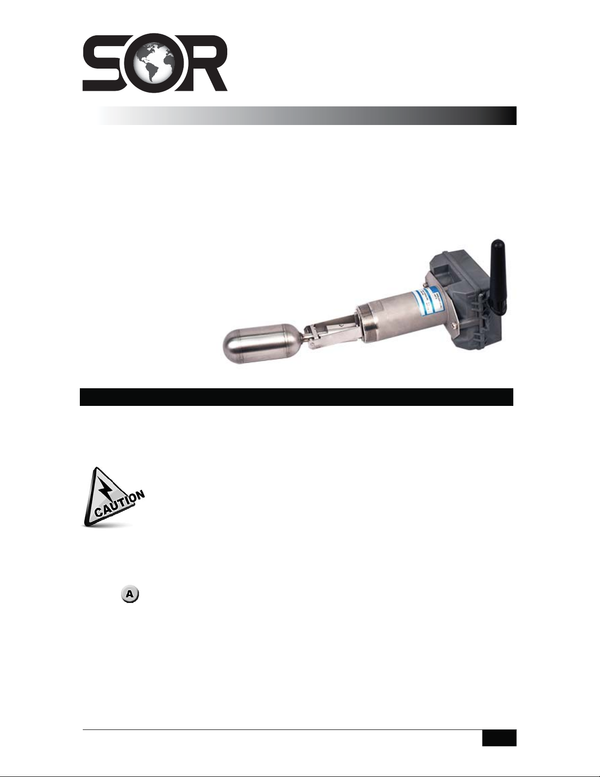
1780 Wireless
Level Switch
General Instructions
The SOR® 1780 Level Switch is a horizontally mounted, float-operated level switch. The
1780 is suitable for plant and OEM applications to detect presence or absence of liquid at a
discrete level.
When the liquid rises, the float extension arm moves a magnet that repels an internal
magnet de-actuating the wireless unit. When the liquid level falls, the float extension arm
moves in the opposite direction, actuating the wireless unit. The 1780 is recommended for
use in clean liquids only.
NOTE: If you suspect that a product is
defective, contact the factory or the SOR
Representative in your area for a return
authorization number (RMA).
This product should only be
installed by trained and
competent personnel.
Mounting
Verify that obstructions are not present in the application that would prevent free float
movement throughout the entire range of motion.
Assure that the mounting provides a horizontal alignment of the switch.
Counterbalance area must be free from metallic particles that may attract to
magnetic components in the 1780 model.
Use a 2” open end wrench on the two flats next to the process connection. Tighten the unit
onto the process connection by rotating clockwise.
To ensure proper operation, the unit must be mounted with either wrench flat horizontal ±1°.
(See
Mount the wireless unit using the two supplied M6X10 screws. Tighten using a 5mm
hex wrench.
Setup and calibrate the wireless unit according to the separtely supplied instructions.
Test the units action by varying the liquid level in the tank.
).
The unit can be mounted with either wrench flat horizontal ±180°
Design and specifications are subject to change without notice.
Form 1564 (09.14) ©SOR Inc.
For latest revision, go to sorinc.com
Registered Quality System to ISO 9001
1/4
Page 2

Wireless Con guration
The following configuration guide is provided as a reference tool only. For the most
complete and up-to-date information regarding configuration, calibration and set up
please refer to the general instructions provided by the manufacturer and included in
the original packaging.
Configuration consists of two parts: Configuration via a HART calibration device and
configuration via the integrated display
Hart Handheld Guided Setup
Open hart on field communicator
Press “right arrow” after finding the device
(2) Configure press “right arrow”
(1) Guided Setup press “right arrow”
(1) Device Setup press “right arrow”
Enter tag # press enter
Enter long tag # press enter
Enter Date press enter
Enter optional description press enter
Enter optional message press enter
Enter optional polling address press enter
Set High Trip Point to 80%
Set Low Trip Point to 20%
Set Dead band to 5%
Select no to configure power source
Configuration is finished
High and Low indication can be switched on the integrated display.
Output -> “Left Button”
If “In Service” -> “Left Button – Toggle Mode”, Else “right Button – Next”
Calibrate -> “Left Button“
Calibrate -> “Left Button – Feedback”
Select first point – High or Low
When sensor is in correct position select “left button to mark” then hit next
When sensor is in opposite position select “left button to mark” then hit next
Then apply
Again, these steps are provided for reference only and are not guaranteed to
reflect periodic software changes. If you have further questions please visit the
manufacturer’s website for the most up to date general instructions.
2/4
Form 1564 (09.14) ©SOR Inc.
Page 3
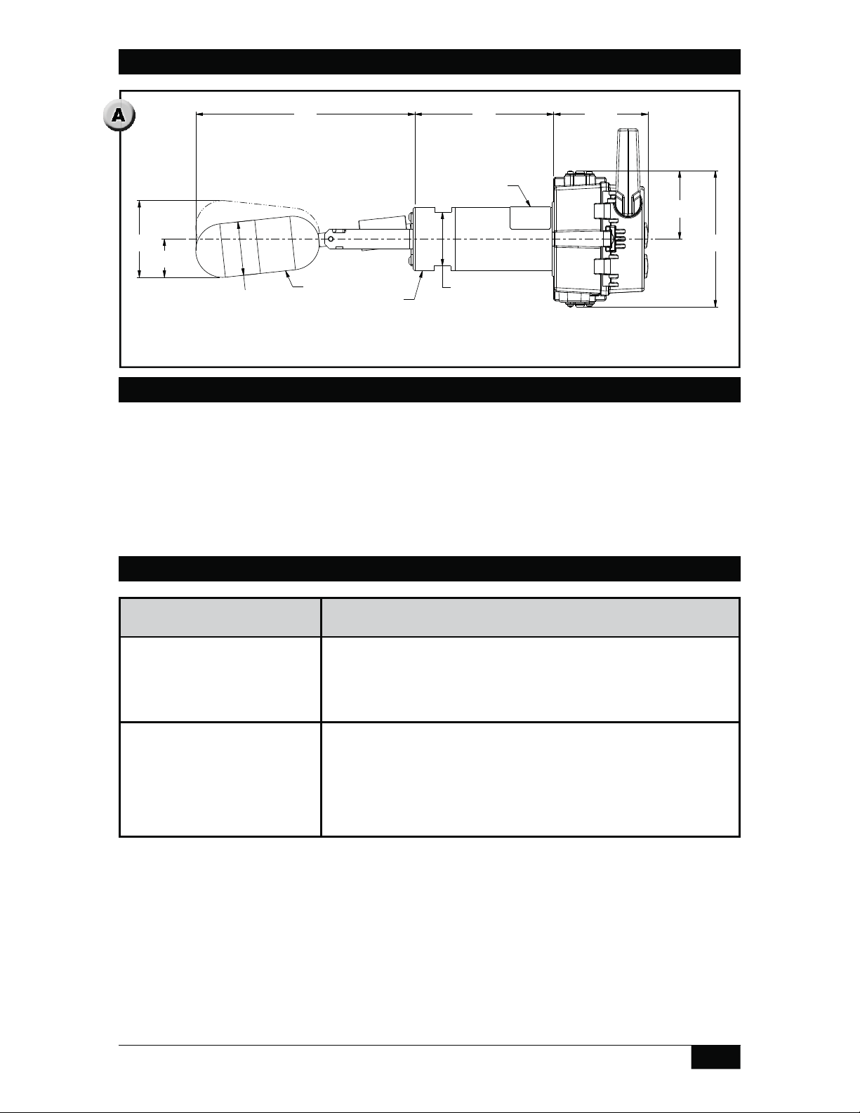
Dimensions
131.4
5.17
207.3
8.16
36.3
1.43
72.7
2.86
50.8
2.00
50.8
2.00
WRENCH
FLATS
64.5 REF
2.54
128.9 REF
5.08
89.3 REF
3.52
NAMEPLATE
2" NPTM
PROCESS
CONNECTION
FLOAT
Linear = mm/inches
Drawing 0390759
Maintenance
Clean the float and counterweight mechanism periodically to assure continued free
movement.
Make no adjustments to the float or counterweight mechanism. They are factory
calibrated for optimum performance.
Troubleshooting
Symptom Probable Cause
The control will not function
when installed but operates
when removed from process
connection.
Liquid is in the vessel at the
actuation level but the unit
does not respond.
a. Float travel is inadequate. Check for internal
vessel obstructions. See Mounting Requirements.
a. The float pivot pin is bound up or dirty. Clean the
float pivot pin.
b. The specific gravity of the liquid is not sufficient
to lift the float.
c.
The float is leaky or collapsed. Contact the factory.
Form 1564 (09.14) ©SOR Inc.
3/4
Page 4

Printed in USA sorinc.com
14685 West 105th Street, Lenexa, KS 66215 913-888-2630 800-676-6794 USA Fax 913-888-0767
4/4
Registered Quality System to ISO 9001
Form 1564 (09.14) ©SOR Inc.
 Loading...