

Page 1
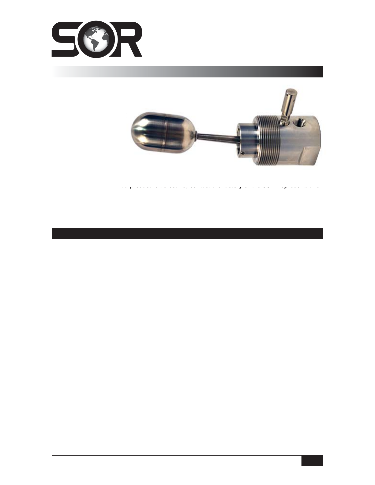
1540 Side Mounted
®
Pneumatic Level Switch
General Instructions
The side mounted SOR® 1540 Pneumatic Level
Switch provides a pneumatic output signal for either
a high or low level condition.
The float moves a magnet
into the field of a
magnetically actuated
sensor. The unit may
be mounted for either
high or low liquid level alarm.
NOTE: If you suspect that a product is defective, contact the factory or the SOR Representative
in your area for a return authorization number (RMA). This product should only be installed by
trained and competent personnel.
1540 Pneumatic Level
matic output signal for either
ition.
et
alarm.
Before Installing the Level Switch
Inspect the unit for any shipment damage.
Check for mechanical clearance. The float must move freely throughout its stroke inside
the vessel.
Use an acceptable thread compound to ensure a leak-free fit and avoid thread
galling when installing the unit into the vessel.
Clean, dry air or gas must be used as the supply media to avoid plugging critical
internal restrictions.
MC or MD (manual check) option can be removed to allow supply fitting to be installed.
Reseal threads with acceptable thread compound and insert to dimension shown.
SUPPLY PRESSURE RANGE: J0 SWITCH – 0-30 psi (0-2 BAR)
J1 SWITCH – 0-80 psi (0-5.5 BAR)
Design and specifications are subject to change without notice.
For latest revision, go to www.sorinc.com
Form 1306 (04.13) ©SOR Inc.
Registered Quality System to ISO 9001
1/4
Page 2
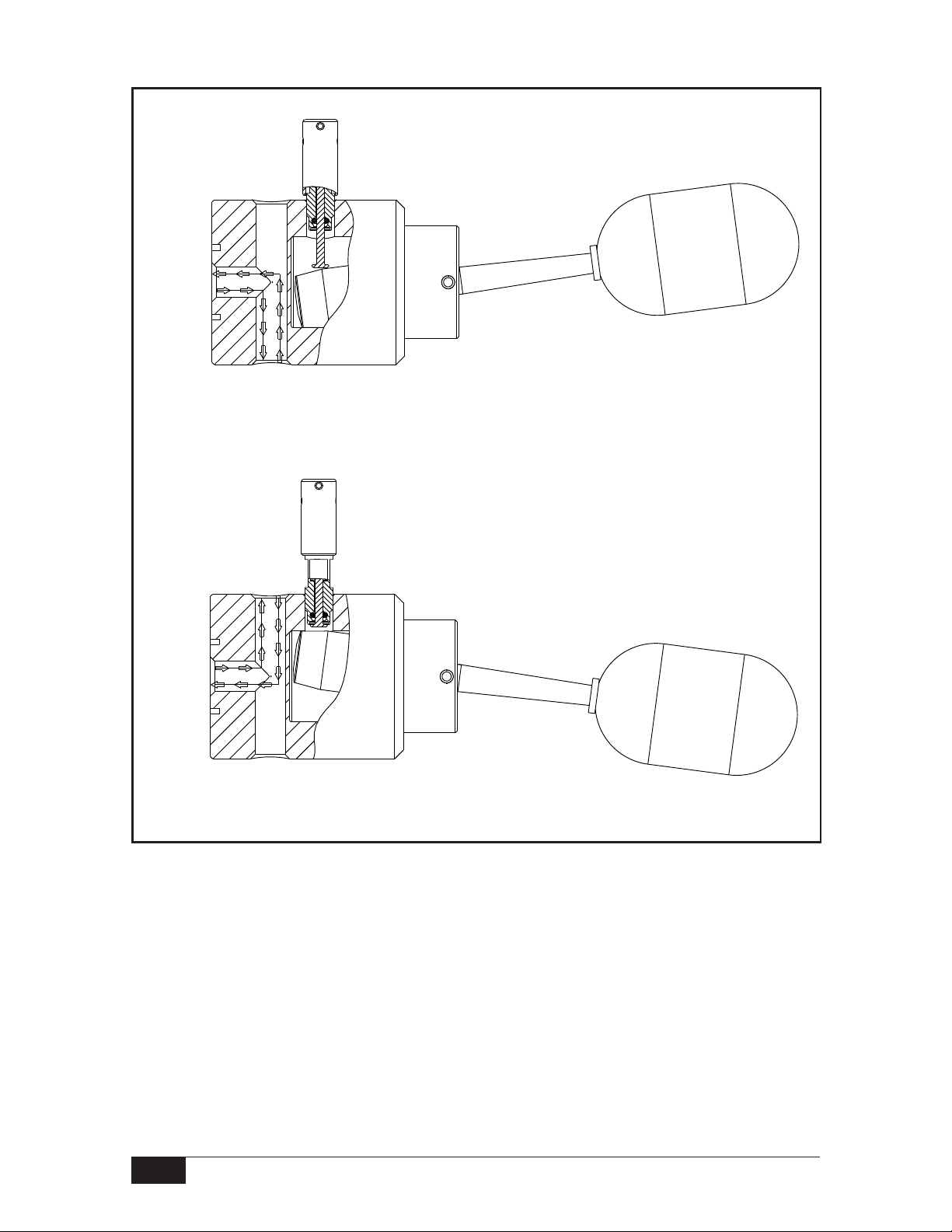
The following drawings show the manual check (MC or MD) option.
* CLOSED
AIR
FLOW
HIGH LEVEL
HIGH LEVEL
AIR
FLOW
* DO NOT PLUG THIS PORT. DURING ACTUATION AND RESET,
TRAPPED AIR IN THE SENSOR MUST ESCAPE FOR THE UNIT
TO OPERATE PROPERLY.
Linear = mm/inches
Drawing 0091448
AIR
FLOW
AIR
FLOW
* CLOSED
LOW LEVEL
LOW LEVEL
2/4
Form 1306 (04.13) ©SOR Inc.
Page 3

Installation
The unit may be mounted using the standard 2” NPT process connection.
MD Remote Option (includes plunger, 20 foot cable and two crimps.)
– Screw plunger to the top of unit.
– Thread the 20’ cable through the hole in plunger and create a 14 inch top loop as
shown below.
– At the bottom of the cable, a second loop can be created as a handle for actuation at
the desired length.
Linear = mm/inches
Drawing 0098626 p.2
PLUNGER
TOP 14” LOOP
CRIMP
REMOTE MANUAL CHECK
MD OPTION
REMOTE CABLE
REMOTE MANUAL CHECK
MD OPTION
CREATE HANDLE AT DESIRED LENGTH
Form 1306 (04.13) ©SOR Inc.
3/4
Page 4

Dimensions
MANUAL CHECK
MC or MD OPTION
32.5
1.28
WRENCH
FLATS
MOUNT THIS AXIS
HORIZONTAL ±5°
MOUNT THIS SURFACE
VERTICAL ±5°
Dimensions are for reference only. Contact the factory for
72.2
2.84
18.4
0.72
1/4"NPTF
INLET
1/4"NPTF
INLET
72.8
2.87
31.0
1.22
12.7
0.50
MANUAL CHECK CABLE
20 FT LONG
MD OPTION ONLY
19.8
0.78
14.3
0.56
2" NPTM PROCESS
CONNECTION
145.3
5.72
certified drawings for a particular model number.
FLOAT
TRAVEL
71
2.8
ACTUATION
56
2.2
36
1.4
ACTUATION
28
1.1
Linear = mm/inches
Drawing 0091448
Replacement Parts
Designator Description
3130040 20’ Remote Cable with two cable crimps*
3100152 Float
9227012 Float & Arm Assembly
9227024 Manual Check Accessory (uses Viton GLT O-ring) (MC)*
9227025 Manual Check Accessory with remote 20’ cable (MD)*
* Unit must have originally been supplied with MC or MD option.
Printed in USA sorinc.com
14685 West 105th Street, Lenexa, KS 66215 913-888-2630 800-676-6794 USA Fax 913-888-0767
4/4
Registered Quality System to ISO 9001
Form 1306 (04.13) ©SOR Inc.
 Loading...