

Page 1

1530 Side Mounted
eat
c Level Switch provides a pneumatic output si
l
v
condition.
w
General Instruc
t
Pneumatic Level Switch
General Instructions
The side mounted SOR® 1530 Pneumatic Level Switch provides a pneumatic output signal
for either a high or low level condition.
The float moves a magnet into the field of a magnetically actuated pneumatic valve. The
pneumatic valve is pilot operated. An amplifying relay provides quick response.
The unit may be mounted for either high or low liquid level alarm by rotating the switch
body. Wrench flats provide ease of rotation.
High Level Pneumatic Output Signal (Direct Acting) Install with pneumatic connections
on the upper side of the body when the unit is tightened into the vessel.
Rising liquid level raises the float upward causing the float stem magnet to repel the
actuating lever magnet and seal the pilot nozzle. Resultant pilot pressure build-up triggers
the amplifying relay to pass pneumatic signal through the output port.
Low Level Pneumatic Output Signal (Reverse Acting) Install with pneumatic connections
on the lower side of the body when the unit is tightened into the vessel.
Falling liquid level lowers the float downward causing the float stem magnet to repel the
actuating lever magnet and seal the pilot nozzle. Resultant pilot pressure build-up
triggers the amplifying relay to pass pneumatic signal through the output port.
NOTE: If you suspect that a product is defective, contact the factory or the SOR Representative
in your area for a return authorization number (RMA). This product should only be installed by
trained and competent personnel.
Form 439 (04.13) ©SOR Inc.
Design and specifications are subject to change without notice.
For latest revision, go to www.sorinc.com
Registered Quality System to ISO 9001
1/4
Page 2
Before Installing the Level Switch
Inspect the unit for any shipment damage.
Check for mechanical clearance. The float must move freely throughout its stroke inside
the vessel.
Use an acceptable thread compound to ensure a leak free fit and avoid thread galling
when installing the unit into the vessel.
The unit may be mounted in any of the following installation arrangements:
2” NPT full or half coupling
3” NPT full coupling (Use in conjunction with 2 x 3” NPT bushing.)
Optional flanged mounting
Optional chamber mounting
Clean dry air or gas must be used as the supply media to avoid plugging critical internal
restrictions and nozzles.
SUPPLY PRESSURE RANGE: 20 TO 60 PSIG
Installation
Connect the supply line to the 1/8” NPT connection stamped Supply. Do not use pipe
compound on the first two threads on pneumatic fitting. The supply media must be
filtered and oil free. Air is the usual media; however, any dry filtered gas can be used.
Connect the output port stamped Output to the unit to be controlled.
NOTE: If the controlled device has a volume of less than 15 cubic inches, the small volume may
cause the output to uctuate. The addition of output volume will stop this uctuation.
VENTING CAUTION: Note the position of the vent connection on the body. It must
be positioned on a horizontal axis either on the right or the left side of the body.
This connection must not be plugged. It is used for either local atmospheric
venting or remote venting through a suitable line run to the designated venting
area. Supply or Output connections must not be connected to the Vent port.
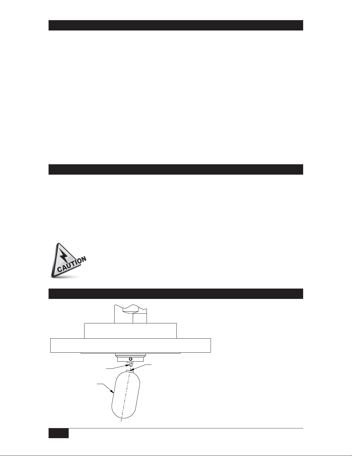
Float Attachment
Place two drops of Loctite
271 inside the threaded
hole of the float.
Thread the float onto the set
screw and hand-tighten.
APPLY TWO DROPS
SET SCREW
FLOAT
LOCTITE 271 INSIDE
THREADED HOLE
OF FLOAT
Linear = mm/inches
Drawing 0390747
NOTE: Do not remove the set
screw as it secures the pivot
arm to the shaft.
2/4
Form 439 (04.13) ©SOR Inc.
Page 3

Dimensions
T
L
98.4
3.88
BODY FLOAT
60.3
2.38
WRENCH
FLATS
50.8
2.00
168.3
CONNECTION
1530 Operating Principle Schematic
Pilot Nozzle
Pilot Pressure
Diaphragm
Vent
PROCESS
2" NPTM
Actuating Lever
Magnet
78.6 REF
Actuator Arm
Float
Magnet
Restriction (0.015”)
59.8
2.35
FLOA
TRAVE
35.6
1.40
MAX
Linear = mm/inches
Drawing 0390026
Output
Form 439 (04.13) ©SOR Inc.
Supply
Restriction Filter
3/4
Page 4

Troubleshooting
Symptom Probable Cause
Float in actuated position
but no output signal.
a. Pilot nozzle-seat worn or damaged. (No seating of
flapper.) Return to the factory or replace the switch.
b.
Actuating lever bound up or dirty. Clean or return to the factory.
c. Damaged relay diaphragm. Replace the relay assembly.
d. Relay orifice plugged. Clean.
e. Insufficient supply pressure adjust to 20-60 psi.
f. Output line clogged. Clean.
Float in de-actuated position
but still receiving an output
signal.
Control will not function
when installed but operates
when removed from vessel.
Liquid in vessel at the
actuation level but unit does
not respond.
Slow response.
Fluttering output. a. Inadequate volume in the output leg.
a. Pilot nozzle plugged. Clean the pilot nozzle.
b. Actuating lever bound up or dirty. (Flapper remains seated.)
Clean or return to factory.
c. Vent screen clogged. Clean.
a. Inadequate float travel. Float travel restricted by the
process connection.
a. Leaky or collapsed float. Replace.
b. Liquid specific gravity too low.
c. Float stem bound up or dirty. Clean.
d. Float travel is obstructed. Verify float can move freely and is
not obstructed when installed.
a. Excessive volume in the output leg.
b. Leaky output line.
Replacement Parts
Part Number Description
3130-052 316SS Float & Actuator Arm Assembly
3130-114 Pneumatic Relay Assembly
sorinc.com
14685 West 105th Street, Lenexa, KS 66215 913-888-2630 800-676-6794 USA Fax 913-888-0767
4/4
Registered Quality System to ISO 9001
Form 439 (04.13) ©SOR Inc.
 Loading...