

Page 1
131/141 Nuclear-Qualified
Differential Pressure Switches
General Instructions
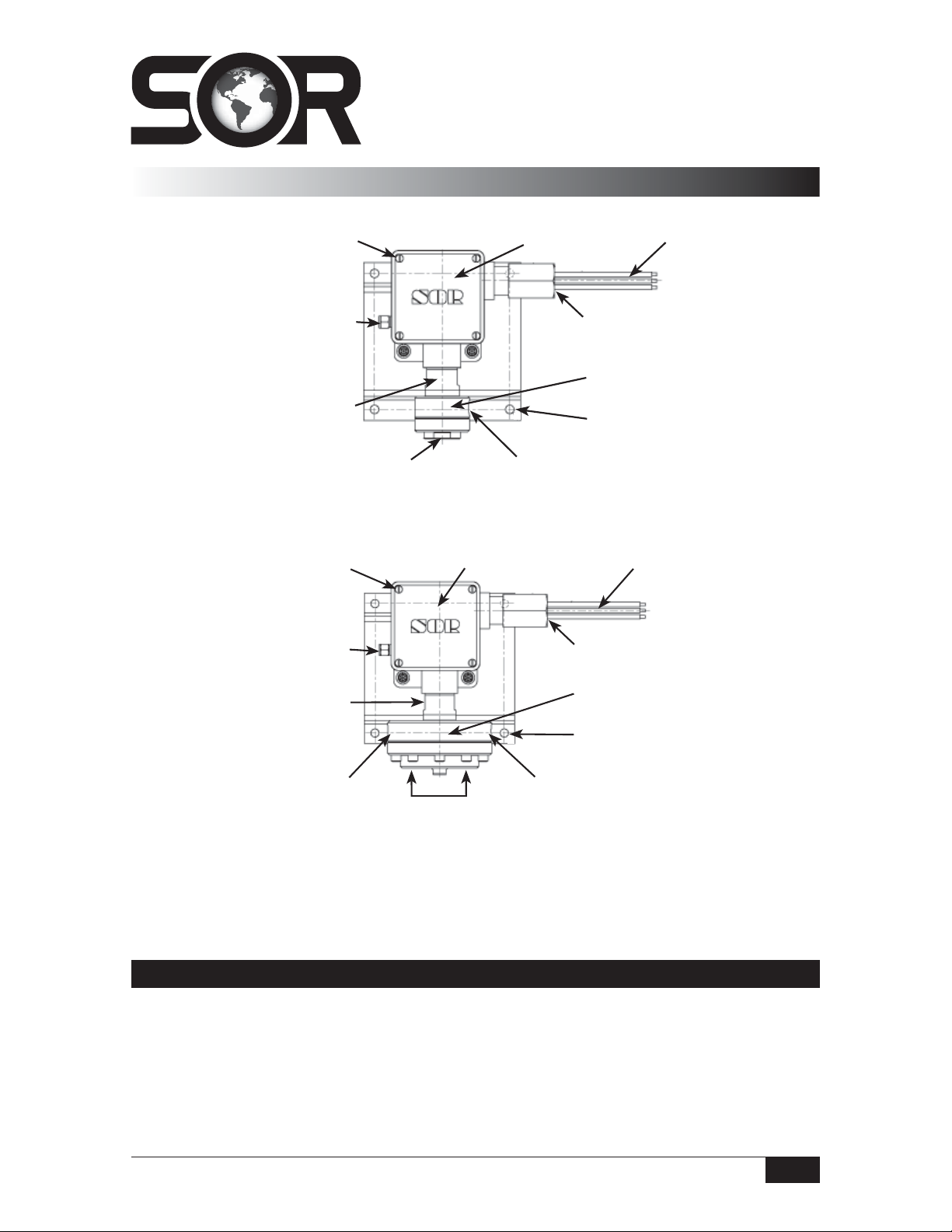
131
1/8” NPT(F) Vent Connection
High Side Process Connection
141
1/8” NPT(F) Vent Connection
Cover Screws
Cover Screws
Body
Housing
3/4” NPT(F) Conduit Connection
Sensor
Mounting Holes
Low Side Process Connection
3/4” NPT(F) Conduit Connection
Wire Leads
Wire LeadsHousing
Body
Low Side Process Connection
High Side Process Connection
NOTE: If you suspect that a product is defective, contact the factory or the SOR® Representative
in your area for a return authorization number (RMA). This product should only be installed by
trained and competent personnel.
Sensor
Mounting Holes
Low Side Process Connection
Installation
Mount pressure switch to rigid vertical mounting surface with four 1/4-20 Grade 5 screws
(not supplied). Torque screws to 70 - 85 in/lbs. The 141 must be oriented with the sensor
down (housing up).
Design and specifications are subject to change without notice.
For latest revision, go to www.sorinc.com
Form 1307 (04.13) ©SOR Inc.
1/4
Page 2
Process Connection
Be certain the process connection is tightened and positioned so bending and torsional
forces imposed on pressure switch are minimal. Use care not to loosen sensor assembly
from housing.
131 - One process connection is provided for the high-pressure side of the device and one
for the low-pressure side.
141 - Two process connections are provided for the high-pressure side of the device and
two for the low-pressure side. On liquid service, the extra process connections should be
used to assist in bleeding the air out of the sensor. On gas service, they may be used to
drain condensate or accumulated liquid.
When the process could be considered dirty in terms of suspended particles,
it is recommended that 20-micron in-line lters be installed on the Hi and Lo
pressure ports.
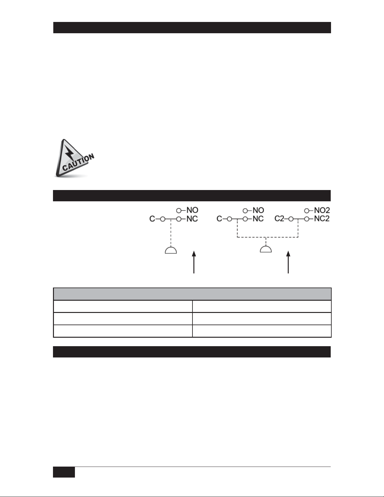
Electrical Connection
Electrical connections are
marked on the insulation
of the wire leads. Conduit
should be installed without
applying strain to the
housing.
Differential
Pressure
Differential
Pressure
Minimum Bend Radius for Wire
Permanent Training 1/2”R
Pulling Tension 1”R
Terminating Junction 1/4”R
Site Storage
Store switch in a dry area in the original shipping package. Shelf life is 10 years for a
maximum ambient temperature of 80°F, based on aging data in SOR Test Report 9058-102.
2/4
Form 1307 (04.13) ©SOR Inc.
Page 3

Calibration
This instrument may be calibrated as a pressure switch (low side vented); however, for
best performance, calibrate under simulated operating conditions.
The 131 has a static shift of -1 psi per 100 psi applied static. If the unit is calibrated without
static pressure applied, the set point should be adjusted to counter the actual static pressure.
To check the set point of a switch, monitor either the common (C) and normally open (NO)
or the common (C) and normally closed (NC) contacts for change of state. Connect the
process connection to a regulated hydraulic or pneumatic pressure source. Monitor with
an accurate pressure measuring standard. Slowly increase or decrease the pressure to
accurately capture the precise moment that the switch changes state. To assure the most
accurate and repeatable results, the switch must be tested in an identical manner each time
the calibration is checked.
Increasing Set Points
If the normal operating pressure is below the set point, then the pressure should be increased from 0
PSI up to the increasing set point and then back down to the reset point. Repeat this cycle
as necessary.
Decreasing Set Points
If the normal operating pressure is above the set point, then the calibration should be checked by first
pressurizing to the normal operating pressure, then reducing the pressure to the decreasing set point,
and then increasing the pressure to the reset point. Repeat this cycle as necessary.
To adjust pressure at which switch will operate, remove cover and tighten the hex head adjusting nut
with a 3/4” wrench to increase pressure; loosen to reduce pressure.
After calibration is complete, reinstall the cover with new gaskets as required by the
Maintenance instructions.
The switching element has been
positioned with a dial indicator to
a tolerance of ±.002 inches. Do
not move this switching element!
Its position has nothing to do with
the set point adjustment. Any
movement can either render the
switch inoperative or cause the
switching element to be damaged
with overpressure.
Switching Element
Do not apply more than 300 psi
positive differential to the switch.
Do not apply a negative differential
of more than 10 psi.
Form 1307 (04.13) ©SOR Inc.
Adjusting Nut
Calibration Scale
3/4
Page 4

Maintenance
Cover Gasket Replacement
SOR provides one new replacement gasket (SOR P/N 8923-180) for each new switch. It
is recommended that the new gasket be installed upon installation of a new switch and
the old gasket be discarded. After that time, the gaskets must be replaced based on the
following schedule:
If Cover Is Not Removed
If the cover is not removed at any time, the gasket need not be replaced for up to five
years. Replace the cover gasket on or before five years from the installation date of a
new gasket.
If Cover Is Removed
The cover may be removed and reinstalled any number of times within a two-year
window without replacing the cover gasket. If the cover is removed within this two-year
window, the cover and gasket assembly must be reinstalled onto the same switch and it
must be oriented in the same way. After two years, the cover gasket must be replaced if
the cover is removed.
NOTE: When removing the cover, if the cover gasket is going to be reused, do not remove the
captive screws. Remove the cover, gasket, and captive screws as one assembly. Reinstall per the
above guidelines (same switch- same orientation).
Instructions For Replacement
Remove the four cover screws. Remove the old gasket. Place new gasket between housing
and cover. Line up holes in cover, gasket and housing. Insert the four screws and torque
each to 7-10 in-lbs.
Printed in USA sorinc.com
14685 West 105th Street, Lenexa, KS 66215 913-888-2630 800-676-6794 USA Fax 913-888-0767
4/4
Form 1307 (04.13) ©SOR Inc.
 Loading...