

Page 1

Trouble Shooting Guide, Electrical
Applicable for Z770i
Contents
General............................................................................................................... 2
1
2 Repair Actions for Manual Test Failures......................................................... 3
2.1 Power On/Off.........................................................................................3
2.2 Software Flash ......................................................................................3
2.3 Charging................................................................................................3
2.4 Hands-Free connection.........................................................................3
2.5 SIM........................................................................................................3
2.6 Open/close flip.......................................................................................3
2.7 Main/Sub Display..................................................................................3
2.8
Main/Sub Display LED.......................................................................... 3
2.9
Keypad LEDs ........................................................................................3
2.10 Keypad Keys.........................................................................................4
2.11 Volume Up/Down Key...........................................................................4
2.12 Real Time clock.....................................................................................4
2.13 Polyphonic Speaker (Loudspeaker, Bas Speaker)................................4
2.14 Hands-Free (PHF) Aux Earphone.........................................................4
2.15 Microphone............................................................................................4
2.16 Hands-Free (PHF) Aux Microphone......................................................4
2.17 Camera..................................................................................................4
2.18 Memory Card.........................................................................................4
2.19 Bluetooth............................................................................................... 4
2.20 Fm Radio...............................................................................................4
2.21
Vibrator..................................................................................................4
2.22
Earphone...............................................................................................4
3 Repair Actions for Go/No Go Test Failures.................................................... 5
Trouble Shooting Guide, Electrical
1208-5031 REV4
Company Internal
4 Repair Actions for Calibration Routine Failures ............................................5
5 Revision History................................................................................................ 6
1001-5712
© Sony Ericsson Mobile Communications
Page 2
1 General
The purpose of this document is to indicate the electrical level repair actions associated with
the different failure symptoms.
For symptoms that have multiple repair actions, the repair actions are listed in order of their
probability of creating a successful repair. The first action has the highest probability, and
subsequent actions have lower probabilities. The intention is for the repair technician to
implement the first repair action and then retest the phone. If the phone continues to fail the
same test, then the technician should continue to the second repair action. If the phone
continues to fail the same test after all of the repair actions are exhausted, then the phone will
be considered not reparable at this level.
This document should be used only after the actions from the Mechanical Trouble Shooting
Guide have been exhausted for the specific symptom.
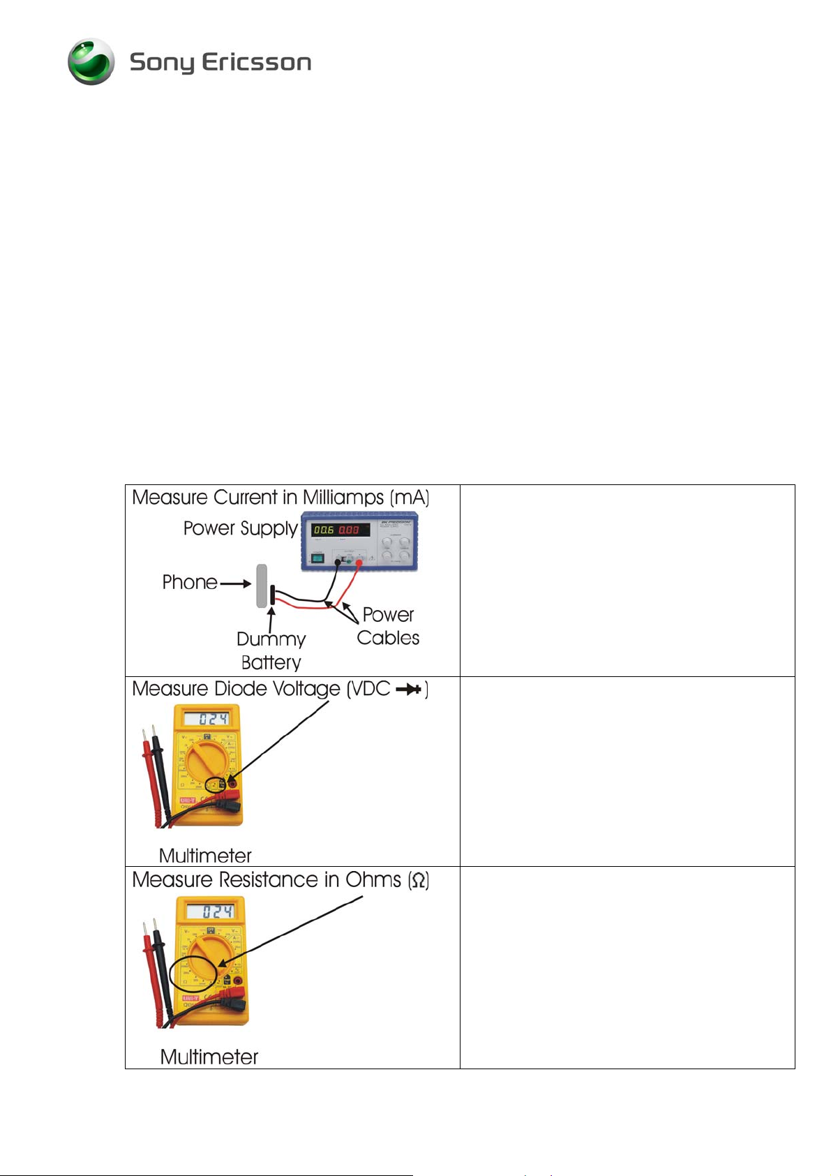
Voltage, current, and resistance information is provided for some symptoms to enable faster
repairs. Perform current measurements using a dummy battery and power supply with digital
current display. The phone should be fully assembled. Perform voltage and resistance
measurements with a multimeter. Purchasing this equipment and performing these
measurements is optional but recommended.
Perform current measurements using a
dummy battery and power supply with digital
current display. The phone should be fully
assembled.
Perform voltage measurements with a
multimeter.
Perform resistance measurements with a
multimeter.
1208-5031 REV4
Company Internal
2(6)
© Sony Ericsson Mobile Communications
Page 3

2 Repair Actions for Manual Test Failures
Failure Failure Symptom Repair Action
2.1 Power
On/Off
2.2 Software
Flash
2.3 Charging
2.4 Hands-Free
connection
Current draw greater than
300 mAmps
Current draw when powered off
Using no current when On/Off button
is pressed and will not start
Hangs at gray display. Constant
vibration. Will not power off
Draws current when pushing On/Off
key, returns to zero
Will not power off
Other symptoms
Charging from power outlet
Charging from computer via USB
Phone stuck in PHF mode when
PHF is not attached
• N1002 inside module N1200
• N1200
• N1210
• N1002 inside module N1200
• N1200
• N1210
• X3100
• B2102
• N2202
• L2200
• X3100
• X2200 if damaged
• X2400
• Z2400
• D2400
• V2421 if short circuit
• V2202
• N2402
• V2420 if short circuit
• N2400
2.5 SIM
2.6 Open/Close Flip
2.7 Main/Sub Display
2.8 Main/Sub LCD LED:
2.9 Keypad LEDs
1208-5031 REV4
Company Internal
• X2403 if damaged
• B4410
• X4200 if damaged.
• Z4200
• Z4201
• Z4202
• X4200 if damaged
• V4205
• X3100 if damaged
• V4206
• V4209
3(6)
© Sony Ericsson Mobile Communications
Page 4

Failure Failure Symptom Repair Action
2.10 Keypad Keys
2.11 Volume Up/Down Key
2.12 Real Time
clock
The clock has to be set after the
battery has been detached
2.13 Polyphonic Speaker (Loudspeaker, Bas Speaker)
2.14 Hands-Free (PHF) Aux Earphone
2.15 Microphone
2.16 Hands-Free (PHF) Aux Microphone
2.17 Camera
• X3100if damaged.
• X3100if damaged.
• X4200 if damaged
• Speaker on Hinge FPC
• X4200 if damaged
• C3137 if short circuit
• C3141 if short circuit
• N3100
• N3101
• L2403 if more than 1 Ohm
• L2404 if more than 1 Ohm
• X3100 if damaged
• N3101
• L2401 if more than 1 Ohm
• L2402 if more than 1 Ohm
• X4200 if damaged
• N2203,N2204
2.18 Memory Card
2.19 Bluetooth
2.20 Fm Radio
2.21 Vibrator
2.22 Earphone
• X2405 if damaged
• N1400
• X2400
• D2105
• N1400
• V2431
• X2400
• B4200
• Earphone on Hinge FPC
1208-5031 REV4
Company Internal
4(6)
© Sony Ericsson Mobile Communications
Page 5

Trouble Shooting Guide, Electrical
3 Repair Actions for Go/No Go Test Failures
Failure Repair Action
Fails any part of Go/No Go testing • Run the calibration routine
Fails Go/No Go test, but passes calibration
Fails Go/No Go test after passing calibration
• Replace the antenna and/or
antenna sub PBA with cable.
• Check X1201 for damage and
replace it necessary
• Return the phone through Go/No Go
testing
• Change X1200 and retest
• Check LCM gasket is missing or not.
4 Repair Actions for Calibration Routine Failures
Failure Repair Action
Fails any part of the calibration routine • Replace X1200 if damaged
N1210 UMTS – Approved Centers Only
•
N2205 UMTS
•
N1200 GSM – Approved Centers Only
•
1208-5031 REV4
Company Internal
1001-5712
© Sony Ericsson Mobile Communications
Page 6

5 Revision History
Rev. Date Changes / Comments
1 2008-03-13 First release
2 2008-04-01 Item 2.13, delete N3100.
3 2008-04-02 Add
C3137,C3141,L2200,V2202,V2431,Z4200,Z4201,Z4202,
N2205.
4 2008-04-07 ADD N3100,V4205,V4206,Z2400
1208-5031 REV4
Company Internal
6(6)
© Sony Ericsson Mobile Communications
 Loading...