

Page 1

Working Instruction, Electrical
Working Instruction, Electrical
Applicable for Z770i
CONTENTS
1 Moisture Sensitivity and Component Baking ......................................3
2 Lead-free Rework...................................................................................4
2.1 Lead-free Symbol..................................................................................4
2.2 Bottom Heat ..........................................................................................4
2.3 Reflow Profile for BGA Rework Station.................................................5
2.4 Inspection..............................................................................................6
3 Replacement of components ................................................................7
3.1 X1200: Conn Antenna...........................................................................8
3.2 X1201: Coax Connector........................................................................8
3.3 X1202:ANT GND Connector Leaf Spring 1p .......................................9
X2200:Battery Connector......................................................................9
3.4
3.5 X2400:System connector.....................................................................10
3.6 X3100: Con X Keyboard connector ....................................................10
3.7 X4200:LCM Connector.......................................................................11
3.8 N1400:Module Bluetooth + FM STLC2592........................................11
3.9 B4200: SMD Vibrator.........................................................................12
3.10 X2403:SIM Card Connector................................................................12
3.11 X2405: MS-Micro Pico holder............................................................ 13
3.12 N3101:ASIC Tjatte3 CSP20................................................................13
3.13 D2105:IC Single bus buffer gate.........................................................14
3.14 D2400:IC IF ISP1508 ES3 (3.5*3.5*0.8)............................................14
3.15 L2401-L2404:Filter 0.0 Hz 0402.........................................................15
3.16 N2203: 2ch-LDO, Vout1=2.8V, Vout2=1.8V, WL-CSP6................... 15
3.17 N2400: IC............................................................................................ 16
3.18 N2402:IC ESD Prot UDFN 6 2x2 mm................................................16
3.19 Ear speaker:Ear Speaker 1107.0 Rectangular...................................... 17
3.20 Loudspeaker:Loudspeaker 1318.0 Oval..............................................18
3.21 V2420-V2422, V4209: Diode Zener 15, V SOD523........................... 18
3.22 E1000:Shield Can Closed small shielding...........................................19
E1001:Shield Can Fence.....................................................................20
3.23
3.24 N2202:IC Vreg SON-6........................................................................20
3.25 B4410:IC Lin,MR sensor....................................................................21
3.26 N2204: LDO1.2 V, 200mA, low noice, CS 5...................................... 21
3.27 B2102:Crystal 32,768 kHz..................................................................22
3.28 N1200: RF-Module Thor Pre-bumped.................................................22
3.29 N1210: RF-Module Squid Pre -bumped..............................................23
3.30 C3137,C3141: Capacitor Ceramic 220,0 nF +/-10% 6,3 V ..................23
3.31 L2200: Ind WW 4.7 uH K3012.............................................................24
3.32 V2202: TRANS V;DUAL_PMOSFET;BYX101603_A;REQ318.......24
3.33 V2431: Diode Protection 0.7 V SOD-882.............................................25
1208-5032 REV 4
Company Internal
© Sony Ericsson Mobile Communications
Page 2

Working Instruction, Electrical
3.34 Z4200,Z4201,Z4202: LC Filter Array 0805 22pF................................25
3.35 N2205: DC/DC Converter....................................................................26
3.36 N3100: IC Amp 9-Pin Flip-Chip...........................................................26
3.37 V4205,V4206: Trans Array..................................................................27
3.38 Z2400: Filter 100, MHz K1210...........................................................27
4 Revision history ...................................................................................28
1208-5032 REV 4
Company Internal
2(28)
© Sony Ericsson Mobile Communications
Page 3

Working Instruction, Electrical
1 Moisture Sensitivity and Component Baking
Some components in this product are moisture sensitive and must be baked prior to use if they
have been exposed to air. These components and their moisture sensitivity levels are
specified in the Electrical Component Placing document. Below is a brief description of
moisture sensitivity levels, but repair centers should visit the JEDEC website for more details
before reworking moisture sensitive components. Search for the most recent version of the
IPC/JEDEC J-STD-033A standard online at http://www.jedec.org/
Level 1 unlimited floor life; does not require dry pack or re-baking.
Level 2 1 year floor life; </=30° C; 60% relative humidity (rh); shipped in dry pack; must
be re-baked after being opened if floor life is exceeded.
Level 2A 4 weeks floor life; </=30° C; 60% rh; shipped in dry pack; must be re-baked after
being opened if floor life is exceeded.
Level 3 168 hours floor life; </=30° C; 60% rh; shipped in dry pack; must be re-baked
after being opened if floor life is exceeded.
Level 4 72 hours floor life; </=30° C; 60% rh; shipped in dry pack; must be re-baked after
being opened if floor life is exceeded.
Parts shipped from the Sony Ericsson Parts Warehouse are most likely NOT shipped in dry
pack. This means the time elapsed between placing the order and receiving the parts must be
considered as time exposed to the environment.
Different moisture sensitivity levels and exposure times create the need for different baking
temperatures and times. More detailed information may be found in the most recent version of
the IPC/JEDEC J-STD-033A standard. The standard is available online at
http://www.jedec.org/
.
1208-5032 REV 4
Company Internal
3(28)
© Sony Ericsson Mobile Communications
Page 4
Working Instruction, Electrical
2 Lead-free Rework
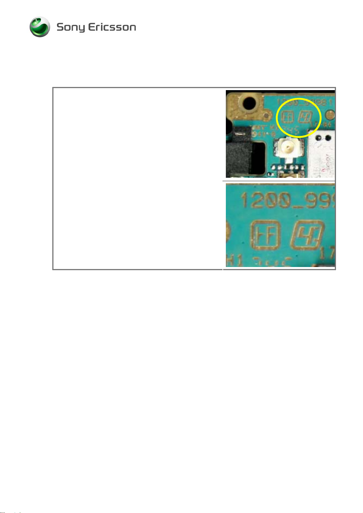
2.1 Lead-free Symbol
NOTE!
• This is a lead-free product!
• All solder wire or paste used with this product
must be lead-free.
• All rework tools that directly contact the solder
must remain lead-free. They must only be used
for lead-free repairs.
2.2 Bottom Heat
Because of the higher temperatures required for lead-free solder, bottom heat is
strongly recommended for rework of all ASICs. This does not include small
transistors or chips, but it does include fine pitch components and BGA type
components.
1208-5032 REV 4
Company Internal
4(28)
© Sony Ericsson Mobile Communications
Page 5

Working Instruction, Electrical
2.3 Reflow Profile for BGA Rework Station
The profile shall be according to SEMC profiling specification below.
Profile parameters are illustrated in table 2.3.
Reflow profile in this document always refers to the reflow profile which is measured
on the board/component with thermocouples and do not refer to the BGA Rework
Stations setting which can vary depending on the machine type and individual
machine. Verification of reflow profile shall be done on each set of equipment.
Table 2.3.1
Ramp rate < 3°C/sec
Ramp rate cooling < 6°C/sec
Time above liquidus 40-70 sec
Minimum temperature 235°C
Maximum component temperature 260 °C
Time above 235°C 10-40 sec
Recommended Total time Approx. 3-5min
The following graph, in table 2.3.2, shows an example of a lead-free profile including
bottom heat and top heat. The profile for specific parts and specific equipment will
vary, but the maximum temperature must not be exceeded.
Table 2.3.2
290
250
200
150
Temperature [ºC]
100
50
Reflow zone
260°C
245°C
230°C
150°C
125°C
0
1208-5032 REV 4
Company Internal
40 80 120 160 200 240 280
Time [Seconds]
© Sony Ericsson Mobile Communications
5(28)
Page 6
Working Instruction, Electrical
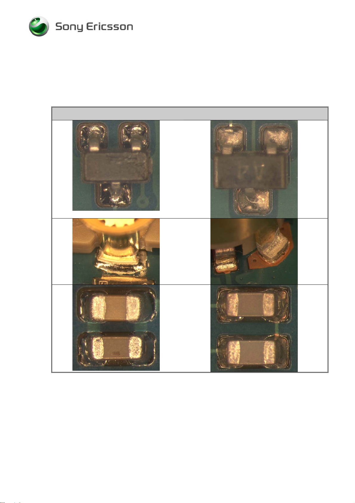
2.4 Inspection
Lead-free solder joints are more difficult to inspect because they do not have shiny
surfaces like leaded solder joints. Also, lead-free solder does not flow as well as
leaded solder, so some of the solder pad area may remain exposed.
Good Leaded Solder Joints
Good Lead-free Solder Joints
1208-5032 REV 4
Company Internal
© Sony Ericsson Mobile Communications
6(28)
Page 7

Working Instruction, Electrical
3 Replacement of components
EQUIPMENT
• Dentist hook
• ESD-gloves (cotton gloves)
• ESD-wristband
• Soldering tools
• Hot Air Station
• Bottom Heat
• BGA Rework Station
• Pair of tweezers
• Solder wick
• Solder paste lead-free (SN 96% Ag 3.5% Cu 0.5%)
• Flux, RMA no-clean flux
CAUTION
• Keep all contact surfaces clean of dirt and hand-grease!
• Remove Film and Labels on PCBA, BB shielding can, and Liquid intrusion indicators in
advance if necessary before repairing PCBA.
MECHANICAL INSTRUCTIONS
For all the following part replacements, disassemble and assemble the phone as described in
.
Working Instruction 1208-3142
1208-5032 REV 4
Company Internal
7(28)
© Sony Ericsson Mobile Communications
Page 8
Working Instruction, Electrical
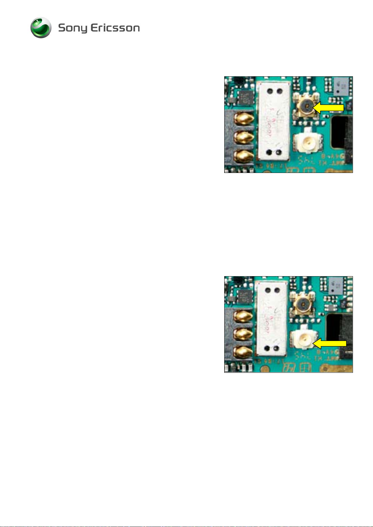
3.1 X1200: Conn Antenna
REMOVE FILM AND LIQUID INTRUSION INDICATORS IN
ADVANCE!
PROTECT THE SYSTEM CONNECTOR AND SIM CONNECTOR WITH
HEAT RESISTANT TAPE
Use BGA Station to replace the Conn Antenna.
!
3.2 X1201: Coax Connector
REMOVE FILM AND LIQUID INTRUSION INDICATORS IN
ADVANCE!
PROTECT THE SYSTEM CONNECTOR AND SIM CONNECTOR WITH
HEAT RESISTANT TAPE
Use BGA Station to replace the Coax Connector.
!
1208-5032 REV 4
Company Internal
8(28)
© Sony Ericsson Mobile Communications
Page 9
Working Instruction, Electrical
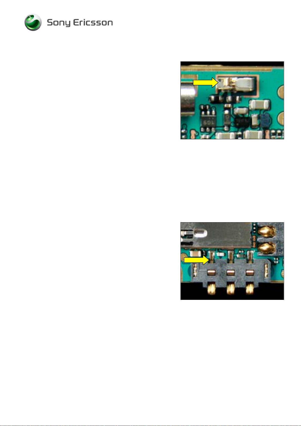
3.3 X1202: ANT GND Connector Leaf Spring 1p
Use Hot Air Station to replace the ANT GND Connector
Leaf Spring 1p
3.4 X2200: Battery Connector
REMOVE FILM AND LIQUID INTRUSION INDICATORS IN
ADVANCE!
PROTECT THE M2 CARD CONNECTOR AND SIM CONNECTOR WITH
HEAT RESISTANT TAPE
Use BGA Station to replace the Battery Connector.
!
1208-5032 REV 4
Company Internal
9(28)
© Sony Ericsson Mobile Communications
Page 10

Working Instruction, Electrical
3.5 X2400: System connector
REMOVE FILM AND PCBA LABELS IN ADVANCE!
PROTECT RF CONNECTOR WITH HEAT RESISTANT TAPE!
Use BGA Station to replace the System connector.
3.6 X3100: Con X Keyboard connector
REMOVE FILM IN ADVANCE!
PROTECT M2 CARD CONNECTOR WITH HEAT RESISTANT TAPE!
Use BGA Station to replace the Con X Keyboard connector.
1208-5032 REV 4
Company Internal
10(28)
© Sony Ericsson Mobile Communications
Page 11

Working Instruction, Electrical
3.7 X4200: LCM Connector
Use BGA Station to replace the LCM Connector.
3.8 N1400: Module Bluetooth + FM STLC2592
Cut the pickup area firstly.
Use BGA Station to replace the BT/FM Module.
1208-5032 REV 4
Company Internal
11(28)
© Sony Ericsson Mobile Communications
Page 12

Working Instruction, Electrical
3.9 B4200: SMD Vibrator
Use Hot Air Station to replace the SMD Vibrator.
3.10 X2403: SIM Card Connector
REMOVE FILM IN ADVANCE!
PROTECT THE M2 CARD CONNECTOR AND BATTERY
CONNECTOR WITH HEAT RESISTANT TAPE
Use BGA Station to replace the SIM Card Connector.
!
1208-5032 REV 4
Company Internal
12(28)
© Sony Ericsson Mobile Communications
Page 13

Working Instruction, Electrical
3.11 X2405: MS-Micro Pico holder
PROTECT THE SIM CONNECTOR, KEYBOARD CONNECTOR,
BATTERY CONNECTOR WITH HEAT RESISTANT TAPE
Use BGA Station to replace the MS-Micro Pico holder.
!
3.12 N3101: ASIC Tjatte3 CSP20
REMOVE PCBA LABELS AND FILM IN ADVANCE!
PROTECT THE RF CONNECTOR AND SYSTEM CONNECTOR WITH
HEAT RESISTANT TAPE
Use BGA Station to replace the ASIC Tjatte3 CSP20.
!
1208-5032 REV 4
Company Internal
13(28)
© Sony Ericsson Mobile Communications
Page 14

Working Instruction, Electrical
3.13 D2105: IC Single bus buffer gate
Cut the pickup area firstly.
Use BGA Station to replace the IC Single bus buffer gate.
3.14 D2400: IC IF ISP1508 ES3 (3.5*3.5*0.8)
Use BGA Station to replace the IC IF ISP1508 ES3
(3.5*3.5*0.8)
1208-5032 REV 4
Company Internal
© Sony Ericsson Mobile Communications
14(28)
Page 15

Working Instruction, Electrical
3.15 L2401-L2404: Filter 0.0 Hz 0402
PROTECT THE SYSTEM CONNECTOR WITH HEAT RESISTANT
!
TAPE
Use Hot Air Station to replace the Filter 0.0 Hz 0402.
3.16 N2203: 2ch-LDO, Vout1=2.8V, Vout2=1.8V, WL-CSP6
PROTECT THE LCM CONNECTOR WITH HEAT RESISTANT TAPE!
Use BGA Repair Station to replace the 2ch-LDO,
Vout1=2.8V, Vout2=1.8V, WL-CSP6.
1208-5032 REV 4
Company Internal
15(28)
© Sony Ericsson Mobile Communications
Page 16

Working Instruction, Electrical
3.17 N2400: IC
REMOVE PCBA LABELS AND FILM IN ADVANCE!
PROTECT THE SIM CONNECTOR AND M2 CONNECTOR WITH
HEAT RESISTANT TAPE
Use BGA Repair Station to replace IC.
!
3.18 N2402:IC ESD Prot UDFN 6 2x2 mm
REMOVE PCBA LABELS IN ADVANCE!
PROTECT THE SYSTEM CONNECTOR AND RF CONNECTOR WITH
HEAT RESISTANT TAPE
Use BGA Station to replace the IC ESD Prot UDFN 6 2x2
mm.
!
1208-5032 REV 4
Company Internal
16(28)
© Sony Ericsson Mobile Communications
Page 17

Working Instruction, Electrical
3.19 Ear speaker: Ear Speaker 1107.0 Rectangular
Use Hot Iron to replace the Ear Speaker 1107.0
Rectangular.
1208-5032 REV 4
Company Internal
© Sony Ericsson Mobile Communications
17(28)
Page 18

Working Instruction, Electrical
3.20 Loudspeaker: Loudspeaker 1318.0 Oval
Use Hot Iron to replace the Loudspeaker 1318.0 Oval
3.21 V2420-V2422, V4209: Diode Zener 15, V SOD523
PROTECT THESYSTEM CONNECTOR WITH HEAT RESISTANT
!
TAPE
PAY MORE ATTENTION ABOUT THE PART DIRECTION!
Use Hot Air Station to replace the Diode Zener 15, V
SOD523
V2420—Left, V2421--Right
V2422:
1208-5032 REV 4
Company Internal
18(28)
© Sony Ericsson Mobile Communications
Page 19

Working Instruction, Electrical
V4209:
3.22 E1000: Shield Can Closed small shielding
REMOVE FILM AND PCBA LABELS IN ADVANCE!
PROTECT THE SIM CONNECTOR AND RF CONNECTOR WITH HEAT
RESISTANT TAPE!
Use BGA Repair Station to remove the Shield Can Closed
small shielding.
1208-5032 REV 4
Company Internal
19(28)
© Sony Ericsson Mobile Communications
Page 20

Working Instruction, Electrical
3.23 E1001: Shield Can Fence
REMOVE BB SHEILDING CAN IN ADVANCE!
PROTECT THE BATTERY CONNECTOR AND LCM CONNECTOR,
SYSTEM CONNECTOR WITH HEAT RESISTANT TAPE
Use BGA Station to replace the Shield Can Fence.
!
3.24 N2202: IC Vreg SON-6
REMOVE FILM IN ADVANCE!
PROTECT SIM CONNECTOR WITH HEAT RESISTANT TAPE!
Use BGA Station to replace the IC Vreg SON-6.
1208-5032 REV 4
Company Internal
20(28)
© Sony Ericsson Mobile Communications
Page 21

Working Instruction, Electrical
3.25 B4410: IC Lin, MR sensor
PROTECT THE LCM CONNECTOR WITH HEAT RESISTANT TAPE!
Use BGA Station to replace the IC Lin, MR sensor.
3.26 N2204: LDO1.2 V, 200mA, low noice, CS 5
PROTECT THE LCM CONNECTOR WITH HEAT RESISTANT TAPE!
Use BGA Station to replace the LDO1.2 V, 200mA, low
noice, CS 5.
1208-5032 REV 4
Company Internal
21(28)
© Sony Ericsson Mobile Communications
Page 22

Working Instruction, Electrical
3.27 B2102: Crystal 32,768 kHz
REMOVE BB SHEILDING CAN IN ADVANCE!
PROTECT BATTERY CONNECTOR WITH HEAT RESISTANT TAPE!
Use BGA Station to replace the Crystal 32,768 kHz.
3.28 N1200: RF-Module Thor Pre-bumped
REMOVE PCBA LABELS IN ADVANCE!
PROTECT SYSTEM CONNECTOR WITH HEAT RESISTANT TAPE!
Use BGA Station to replace the pre-bumped Mod Radio
Thor GSM/EDGE.
.
1208-5032 REV 4
Company Internal
22(28)
© Sony Ericsson Mobile Communications
Page 23

Working Instruction, Electrical
3.29 N1210: RF-Module Squid Pre -bumped
REMOVE PCBA LABELS IN ADVANCE!
PROTECT M2 CONNECTOR AND KEYBOARD CONNECTOR WITH
HEAT RESISTANT TAPE
Use BGA Station to replace the pre-bumped Mod Radio
WCDMA Squid.
!
3.30 C3137, C3141: Capacitor Ceramic 220,0 nF +/-10% 6,3 V
REMOVE BB SHEILDING CAN LID IN ADVANCE!
Cut the pickup area firstly.
Use Hot Air Station to replace the Capacitor Ceramic 220,0
nF +/-10% 6,3 V
.
1208-5032 REV 4
Company Internal
23(28)
© Sony Ericsson Mobile Communications
Page 24

Working Instruction, Electrical
3.31 L2200: Ind WW 4.7 uH K3012
REMOVE BB SHEILDING CAN LID IN ADVANCE!
Use Hot Air Station to replace the Ind WW 4.7 uH K3012.
3.32 V2202: TRANS V;DUAL_PMOSFET;BYX101603_A;REQ318
REMOVE SHEILDING FILM IN ADVANCE!
PROTECT SIM CARD CONNECTOR WITH HEAT RESISTANT TAPE!
Use BGA Station to replace the TRANS
V;DUAL_PMOSFET;BYX101603_A;REQ318.
.
1208-5032 REV 4
Company Internal
24(28)
© Sony Ericsson Mobile Communications
Page 25

Working Instruction, Electrical
3.33 V2431: Diode Protection 0.7 V SOD-882
PROTECT SYSTEM CONNECTOR WITH HEAT RESISTANT TAPE!
Use BGA Station to replace the Diode Protection 0.7 V
SOD-882.
3.34 Z4200, Z4201, Z4202: LC Filter Array 0805 22pF
PROTECT LCM CONNECTOR WITH HEAT RESISTANT TAPE!
Use BGA Station to replace the LC Filter Array 0805 22pF.
Note: From left to right, their positions are Z4200, Z4201,
and Z4202.
.
1208-5032 REV 4
Company Internal
25(28)
© Sony Ericsson Mobile Communications
Page 26

Working Instruction, Electrical
3.35 N2205: DC/DC Converter
REMOVE SHEILDING FILM IN ADVANCE!
PROTECT SIM CARD CONNECTOR AND RF CONNECTOR WITH
HEAT RESISTANT TAPE
Use BGA Station to remove the small shielding firstly.
Use BGA Station to replace the DC/DC Converter.
Use BGA Station to re-solder the small shielding.
!
3.36 N3100: IC Amp 9-Pin Flip-Chip
REMOVE BB SHEILDING CAN LID IN ADVANCE!
Use BGA Station to replace the IC Amp 9-Pin Flip-Chip .
.
1208-5032 REV 4
Company Internal
26(28)
© Sony Ericsson Mobile Communications
Page 27

Working Instruction, Electrical
3.37 V4205,V4206: Trans Array
PROTECT LCM CONNECTOR WITH HEAT RESISTANT TAPE!
Use BGA Station to replace the Trans Array.
Left: V4206 Right: V4205
3.38 Z2400: Filter 100, MHz K1210
PROTECT LCM CONNECTOR AND RF CONNECTOR WITH
HEAT RESISTANT TAPE
Use BGA Station to replace the Filter 100, MHz K1210.
.
!
1208-5032 REV 4
Company Internal
27(28)
© Sony Ericsson Mobile Communications
Page 28

Working Instruction, Electrical
4 Revision history
Rev. Date Changes / Comments
1 2008-03-17 First release
2 2008-04-01 Delete N3100
3 2008-04-03 Add C3137, C3141, L2200, V2202, V2431,
Z4200,Z4201,Z4202, N2205
4 2008-04-07 Add N3100,V4205,V4206,Z2400
1208-5032 REV 4
Company Internal
28(28)
© Sony Ericsson Mobile Communications
 Loading...