

Page 1

Working Instruction, Mechanical
Working Instruction, Mechanical
Applicable for W710, Z710
CONTENTS
1 General...................................................................................... 3
1.1 Phone Portions – Base and Flip .............................................3
1.2 Using Hand and ESD Protection............................................. 3
1.3 Protection of Displays, Lenses, and Windows...................... 3
1.4 Acceptable Pry Tools...............................................................4
1.5 Tools and Equipment...............................................................4
1.6 General Cautions...................................................................... 4
2 Disassembly ............................................................................. 5
2.1 Base Portion Disassembly ...................................................... 5
2.1.1 Battery Door Removal ........................................................... 5
2.1.2 Battery Removal....................................................................6
2.1.3 Outer Base Cover Removal ..................................................7
2.1.4 Antenna Cover Removal ....................................................... 9
2.1.5 Circuit Board Removal ........................................................10
2.1.6 Inner Base Cover Removal ................................................. 12
2.2 Flip Portion Disassembly ......................................................13
2.2.1 Perform Base Portion Disassembly.....................................13
2.2.2 Outer Flip Cover Removal................................................... 13
2.2.3 Inner Flip Cover Removal.................................................... 16
3 Reassembly ............................................................................ 17
3.1 Flip Portion Reassembly .......................................................17
3.1.1 Inner Flip Cover Installation................................................. 17
3.1.2 Outer Flip Cover Installation................................................ 19
3.2 Base Portion Reassembly ..................................................... 24
3.2.1 Perform Flip Portion Reassembly........................................24
3.2.2 Inner Base Cover Installation .............................................. 24
3.2.3 Circuit Board Installation .....................................................26
3.2.4 Antenna Cover Installation .................................................. 29
3.2.5 Outer Base Cover Installation .............................................30
3.2.6 Battery Installation...............................................................35
3.2.7 Battery Door Installation ...................................................... 36
4 Part Replacement................................................................... 37
4.1 Battery Door............................................................................ 37
4.2 Phone Label ............................................................................37
4.2.1 Label Removal ....................................................................37
4.2.2 Label Installation .................................................................38
3/000 21-1/FEA 209 544/601 C
Company Internal
Communications AB
© Sony Ericsson Mobile
Page 2

Working Instruction, Mechanical
4.3 Outer Base Cover ...................................................................39
4.4 Rear Speaker Box................................................................... 46
4.5 Rear Speaker Cloth ................................................................ 49
4.6 Rear Speaker ..........................................................................52
4.7 Volume Key.............................................................................56
4.8 Camera key ............................................................................. 58
4.9 Phone Lock Key .....................................................................59
4.10 Infrared Window ..................................................................... 61
4.11 Antenna Cover........................................................................62
4.12 SIM Tape.................................................................................. 63
4.13 System Connector..................................................................64
4.14 Keypad and Dome Array........................................................65
4.14.1 Removal ..............................................................................65
4.14.2 Installation ........................................................................... 66
4.15 Microphone Cloth...................................................................69
4.16 Side Key Flex Assembly........................................................ 70
4.17 Co-Brand Label and Flip Bumper .........................................73
4.18 Inner Base Cover....................................................................75
4.19 Flip Screw Cover .................................................................... 76
4.20 Outer Flip Cover ..................................................................... 77
4.21 Camera Ring (Applies to W710 Only)...................................78
4.22 Inner Flip Cover ......................................................................78
4.23 Receiver ..................................................................................80
4.24 Magnet.....................................................................................82
4.25 Vibrator.................................................................................... 83
4.26 Display Assembly...................................................................84
4.27 Main Flex Assembly ...............................................................85
4.28 Flip Flex Assembly.................................................................91
4.29 Camera Module....................................................................... 95
4.30 Flip Frame ...............................................................................95
5 Revision History................................................................... 101
3/000 21-1/FEA 209 544/601 C
© Sony Ericsson Mobile Communications AB
2(101)
Page 3
Working Instruction, Mechanical
1 General
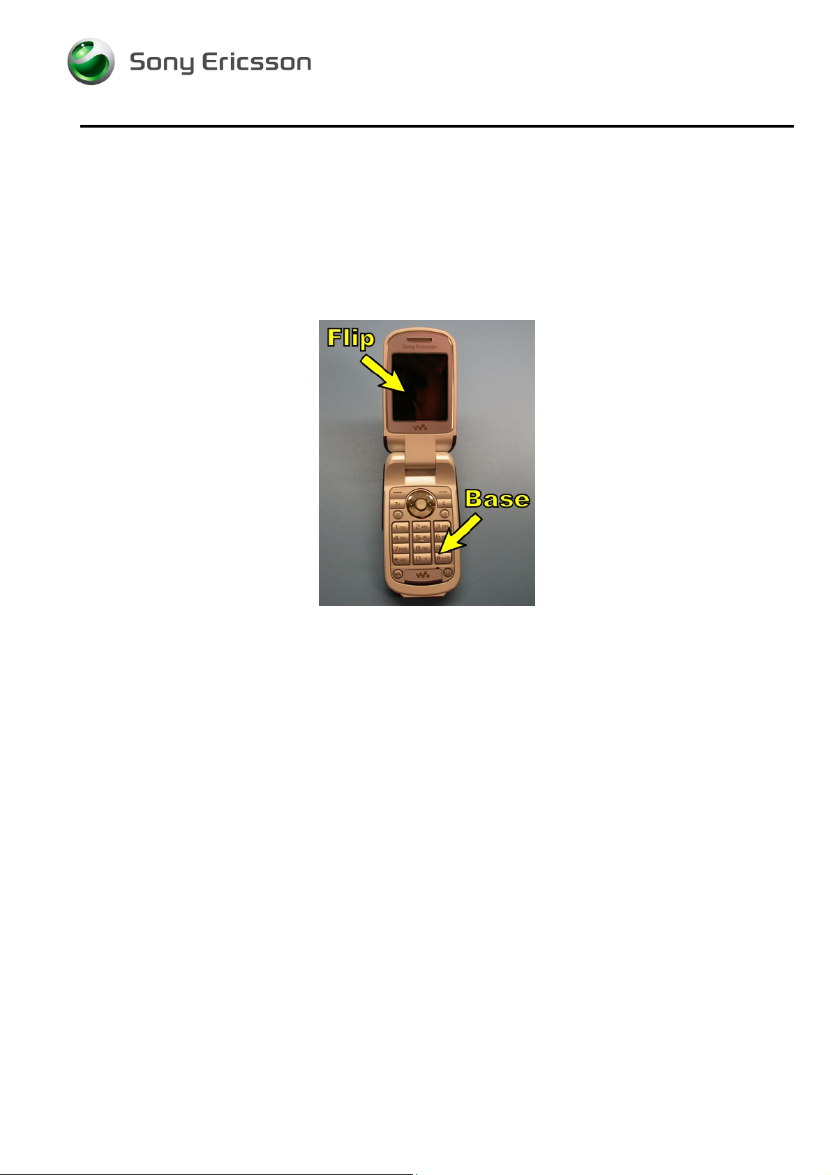
1.1 Phone Portions – Base and Flip
This document uses the hinge of the phone to divide the phone into two portions. The portion of the
phone that contains the keypad will be referred to as the base. The portion of the phone that contains
the displays will be referred to as the flip. The basic disassembly and reassembly procedures will be
structured around these two distinct portions.
1.2 Using Hand and ESD Protection
When handling this product, keep all surfaces clean of dirt, dust, debris, and hand oil. Use
appropriate ESD precautions when working on this product. The use of finger cots or gloves, an ESD
mat, and an ESD wrist strap are required at minimum.
1.3 Protection of Displays, Lenses, and Windows
Any time the screen portion of a display assembly, the windows of a display cover, or a camera lens
is unprotected and exposed, add a protective film over the exposed part to reduce the amount of
dust, finger prints, debris, and/or damage that the part may obtain.
3/000 21-1/FEA 209 544/601 C
Company Internal
Communications AB
© Sony Ericsson Mobile
Page 4
Working Instruction, Mechanical
1.4 Acceptable Pry Tools
Whenever the phrase “pry tool” is used, a nylon pointer or a front opening tool may be used
depending on the user’s preference.
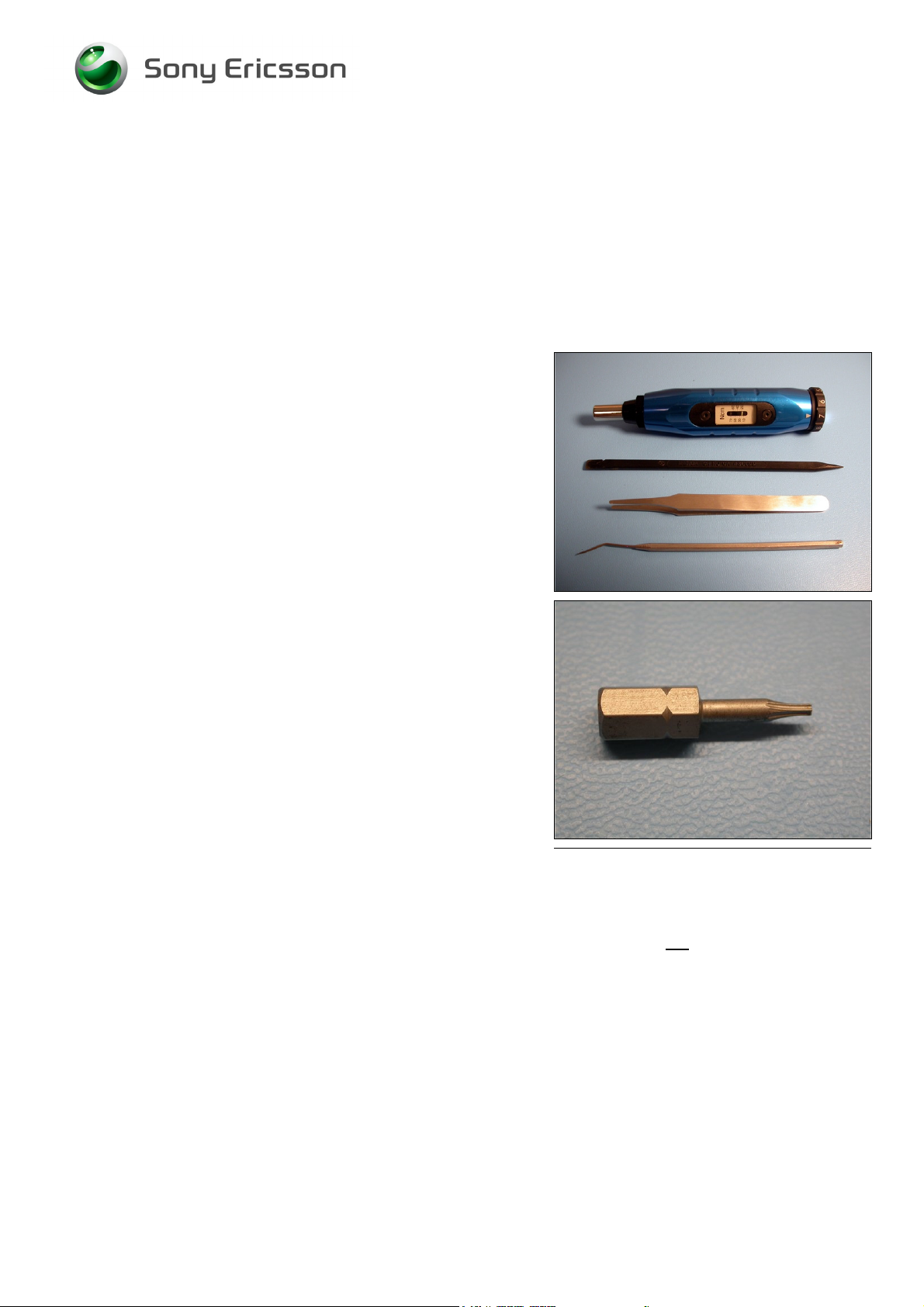
1.5 Tools and Equipment
The following tools and equipment should be available while performing the procedures.
Standard Tools
• Torque Driver
• Nylon Pointer
• Style 2A Tweezers – Rounded Tip
• Dental Hook
Product Specific Tools
• Torx size 6 Bit (T6 bit)
1.6 General Cautions
The following cautions are considered to be generic for all products and will not be repeated in the
Disassembly, Reassembly, and Replacements sections:
WITCH OFF THE PHONE AND REMOVE ANY MEMORY STICK BEFORE THE START OF THE DISASSEMBLY!
• S
EEP ALL CONTACT SURFACES CLEAN!
• K
E CAREFUL WHEN USING TOOLS LIKE THE DENTIST HOOK, TWEEZERS, PRY TOOLS, ETC. TO AVOID
• B
SCRATCHES OR DAMAGES TO THE EXTERIOR AND INTERIOR PARTS OF THE PHONE!
• B
E CAREFUL NOT TO DAMAGE ANY CONTACT SPRINGS!
EMEMBER TO REMOVE THE PROTECTION FOILS ON NEW PARTS SUCH AS THE FRONT COVER AND LCD!
• R
EVER TOUCH THE DISPLAY GLASS!
• N
3/000 21-1/FEA 209 544/601 C
© Sony Ericsson Mobile Communications AB
4(101)
Page 5
Working Instruction, Mechanical
2 Disassembly
2.1 Base Portion Disassembly
The following subsections make up the “Base Portion Disassembly” procedure. These subsections
are arranged in the order that they must be performed to properly disassemble the base portion of
this product. Before starting disassembly, check whether there is a protective film over the two
display windows. If one or both of the windows lack a protective film, clean the unprotected
window(s) and add a protective film.
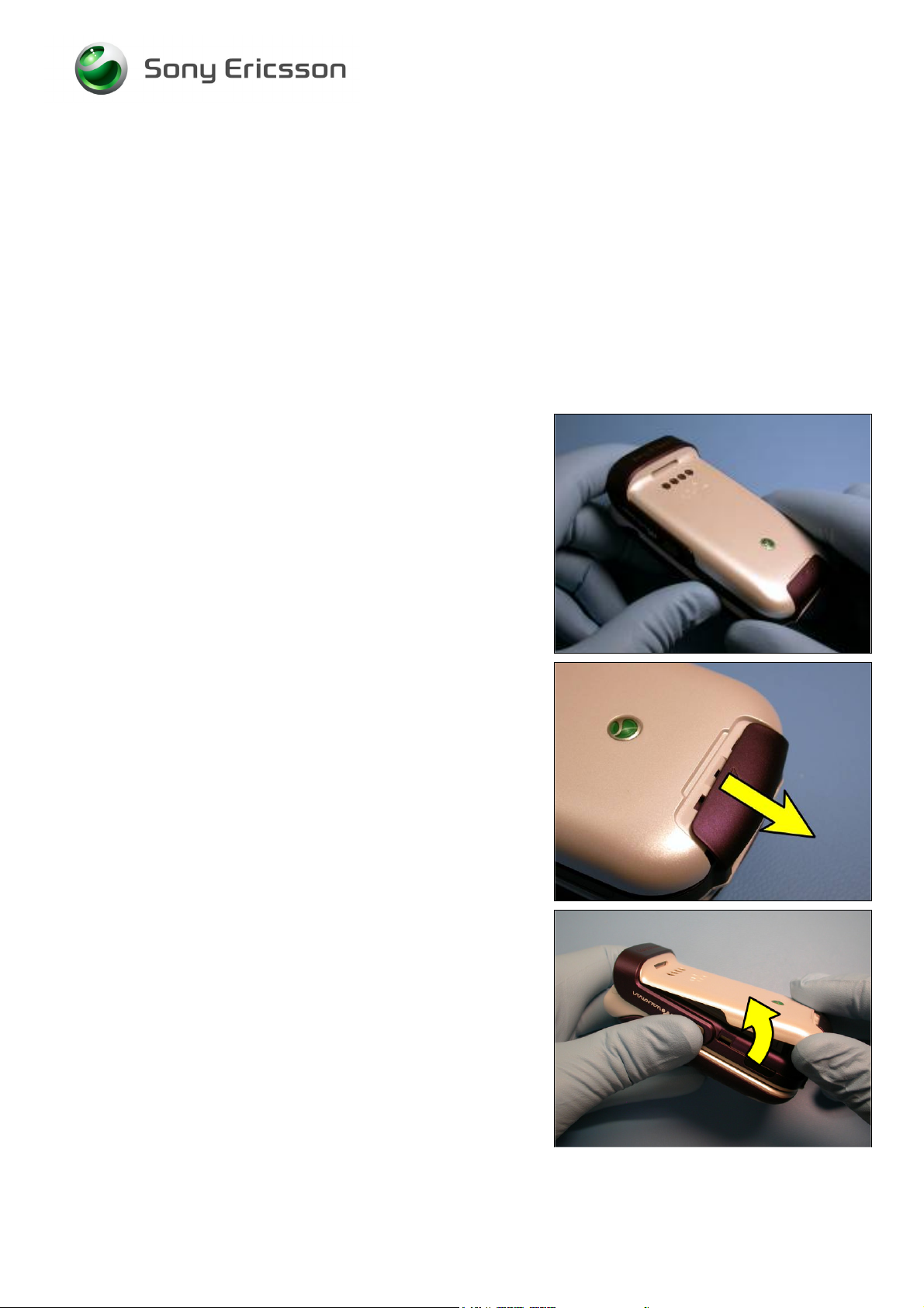
2.1.1 Battery Door Removal
1. Position the phone with the battery door toward you.
2. Slide the latch on the system connector end of the
battery door in the direction shown.
3. Lift the end of the battery door containing the latch
about 30 degrees from the phone as indicated.
3/000 21-1/FEA 209 544/601 C
© Sony Ericsson Mobile Communications AB
5(101)
Page 6
Working Instruction, Mechanical
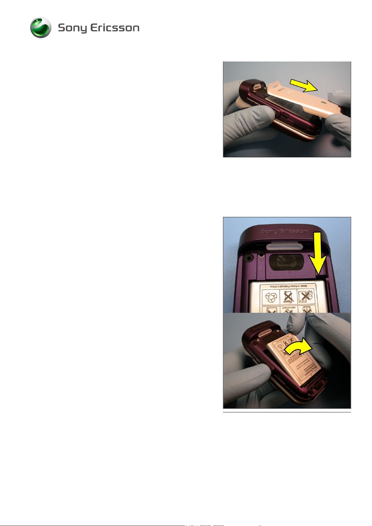
4. Pull the battery door away from the phone as
shown.
2.1.2 Battery Removal
All of the sections of the base portion disassembly preceding this section must be performed in
sequential order before the steps listed below can be performed.
NOTE!
DO NOT TAP THE PHONE AGAINST A HARD SURFACE
IN AN ATTEMPT TO GET THE BATTERY OUT. DAMAGE
TO THE PHONE MAY RESULT
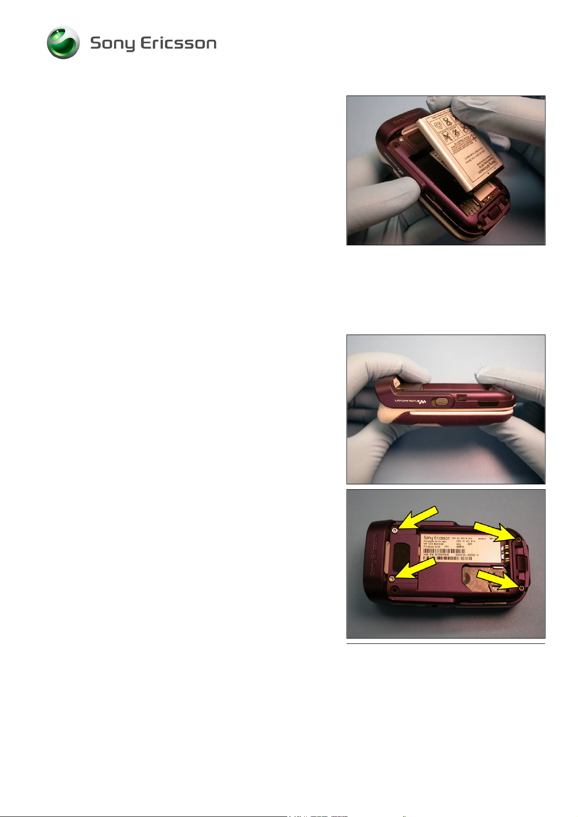
1. Lift the end of the battery from the battery cavity
using the access point indicated. Use a pry tool if
needed.
!
3/000 21-1/FEA 209 544/601 C
© Sony Ericsson Mobile Communications AB
6(101)
Page 7
Working Instruction, Mechanical
2. Once the end of the battery being lifted is clear of
the battery cavity, lift the battery from the phone and
set it aside.
2.1.3 Outer Base Cover Removal
All of the sections of the base portion disassembly preceding this section must be performed in
sequential order before the steps listed below can be performed.
1. Close the flip and base portions of the phone
together.
2. Use a torque driver with a T6 bit to remove the four
screws indicated.
3/000 21-1/FEA 209 544/601 C
© Sony Ericsson Mobile Communications AB
7(101)
Page 8
Working Instruction, Mechanical
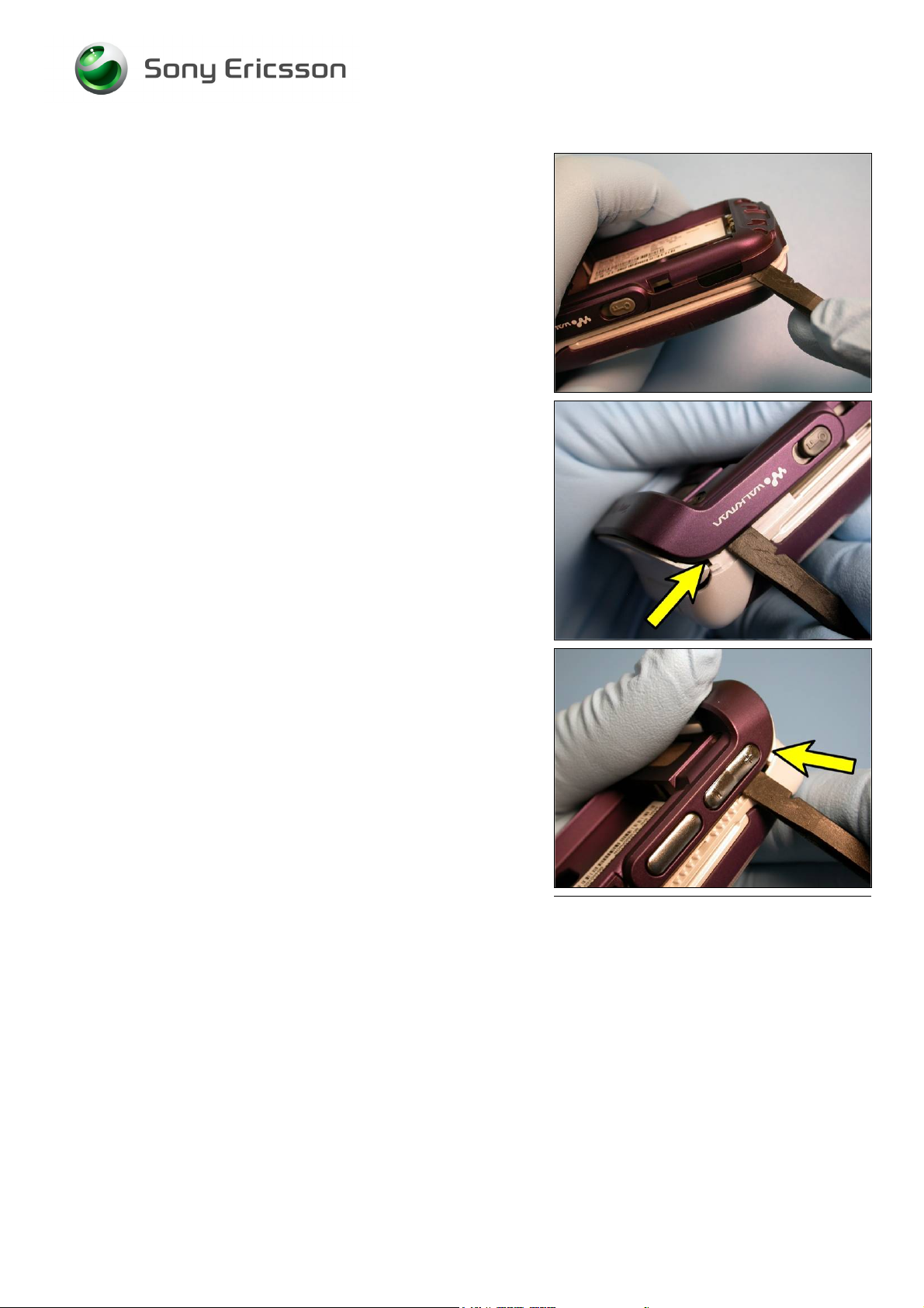
3. Insert the flat end of a pry tool in the seam near the
system connector where the inner and outer base
covers come together.
4. Gently slide the pry tool along the seam until you
reach the corner of the antenna cover. The two
base covers should now be unlatched along that
side.
5. Repeat the previous two steps on the other side of
the outer base cover.
3/000 21-1/FEA 209 544/601 C
© Sony Ericsson Mobile Communications AB
8(101)
Page 9
Working Instruction, Mechanical
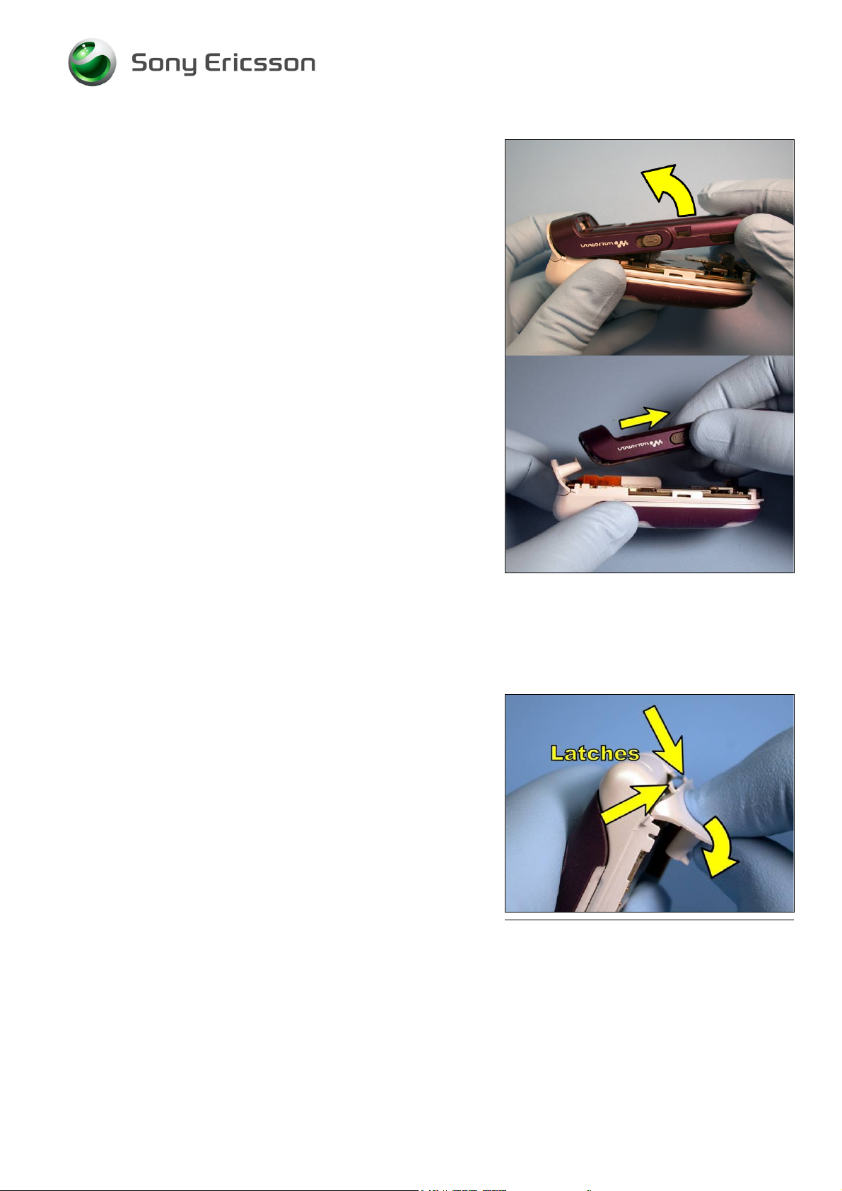
6. Rotate the outer base cover up ~ 30 degrees from
the rest of the phone and pull the lifted end of the
outer base cover away from the phone to separate
the outer base cover from the phone.
NOTE!
THE VOLUME KEY, CAMERA KEY, ANTENNA COVER,
REAR SPEAKER BOX
WHILE REMOVING THE OUTER BASE COVER
, AND RF PLUG MAY FALL OUT
.
2.1.4 Antenna Cover Removal
All of the sections of the base portion disassembly preceding this section must be performed in
sequential order before the steps listed below can be performed.
1. Grip the antenna cover as indicated and rotate it
toward the circuit board to release the latches on
each side.
3/000 21-1/FEA 209 544/601 C
© Sony Ericsson Mobile Communications AB
9(101)
Page 10
Working Instruction, Mechanical
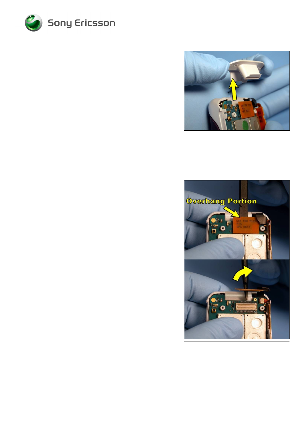
2. Remove the antenna cover by pulling the antenna
cover directly away from the edge of the circuit
board that it is adjacent too.
2.1.5 Circuit Board Removal
All of the sections of the base portion disassembly preceding this section must be performed in
sequential order before the steps listed below can be performed.
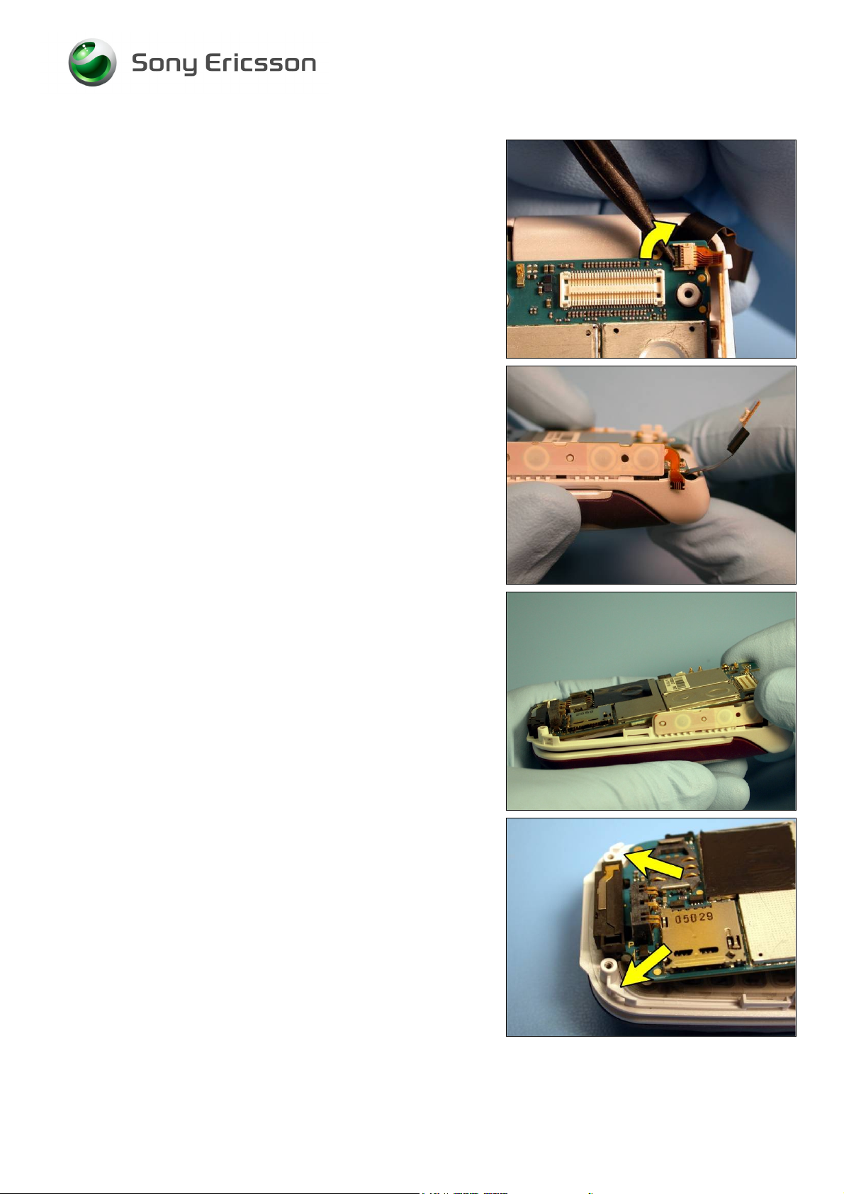
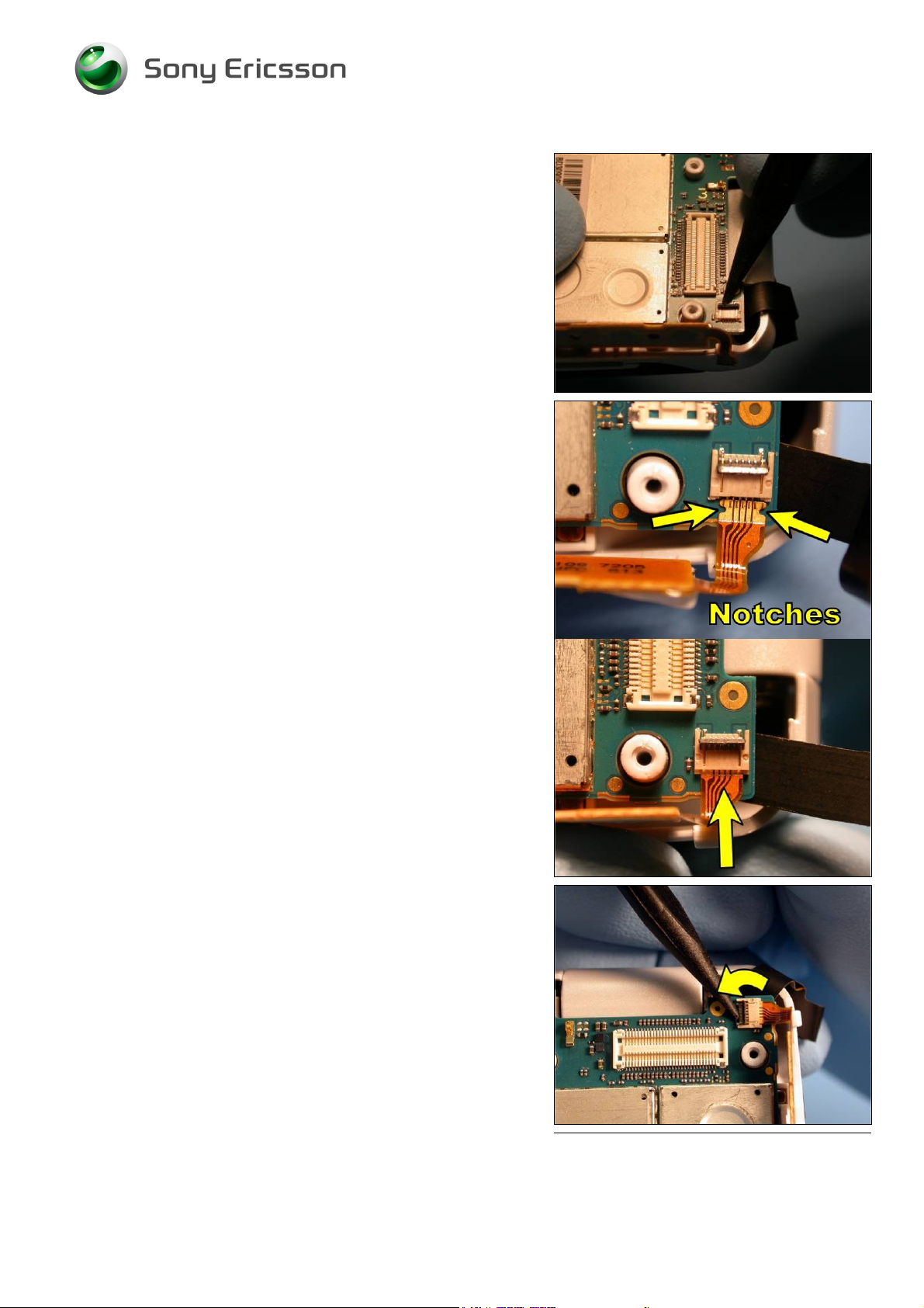
1. Insert the flat end of a nylon pointer between the
hinge cover and the portion of the flex film’s board
connection that overhangs the edge of the circuit
board.
2. Hold the circuit board in place and disconnect the
main flex film assembly from the circuit board by
twisting the nylon pointer as shown.
3/000 21-1/FEA 209 544/601 C
© Sony Ericsson Mobile Communications AB
10(101)
Page 11
Working Instruction, Mechanical
3. Rotate the black portion of the side key flex film’s
board connector 90 degrees toward the side key flex
film assembly.
4. Using style 2A tweezers, remove connection portion
of the side key flex film from its connector and
position it on the outside of the phone as indicated.
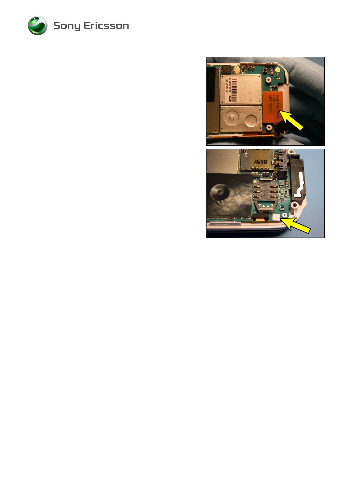
5. Lift the end of the circuit board, nearest the hinge,
up from the phone just enough so that the board is
clear of the two screw bosses.
6. Slide the lifted circuit board 5 or 6 mm towards the
hinge so that the edge of the board is clear of the
two tabs indicated.
3/000 21-1/FEA 209 544/601 C
© Sony Ericsson Mobile Communications AB
11(101)
Page 12
Working Instruction, Mechanical
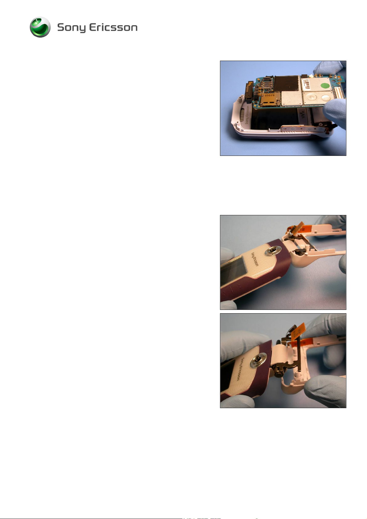
7. Lift the board from the phone.
2.1.6 Inner Base Cover Removal
All of the sections of the base portion disassembly preceding this section must be performed in
sequential order before the steps listed below can be performed.
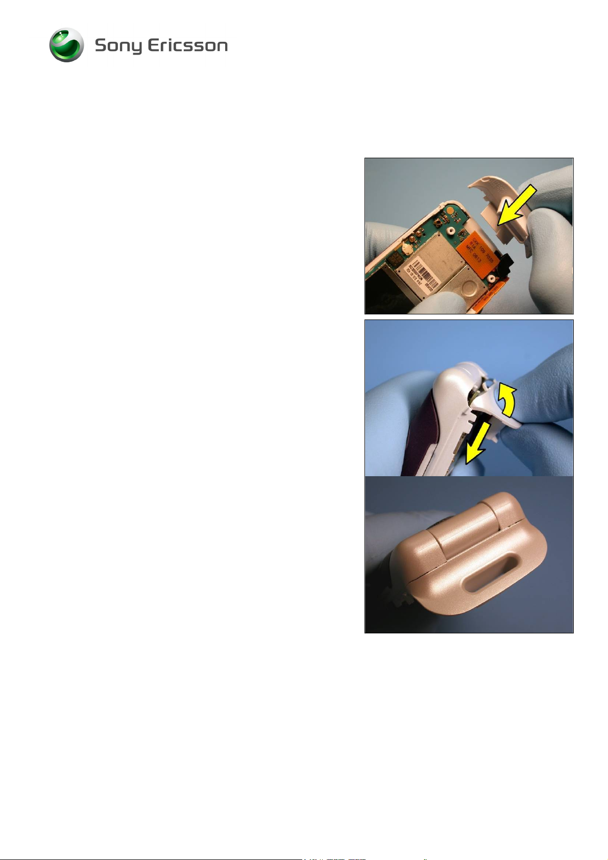
1. Open the phone.
2. Slide the inner base cover directly away from the
metal hinge until the inner base cover is separated
from the flip portion of the phone.
NOTE:
BE CAREFUL TO NOT DAMAGE THE MAIN FLEX
ASSEMBLY
.
3/000 21-1/FEA 209 544/601 C
© Sony Ericsson Mobile Communications AB
12(101)
Page 13
Working Instruction, Mechanical
2.2 Flip Portion Disassembly
The following subsections make up the “Flip Portion Disassembly” procedure. These subsections are
arranged in the order that they must be performed to properly disassemble the flip portion of this
product.
2.2.1 Perform Base Portion Disassembly
The base portion of this phone must be disassembled before the flip portion disassembly procedure
can be performed.
2.2.2 Outer Flip Cover Removal
The entire base portion disassembly must be performed before the steps listed below can be
performed.
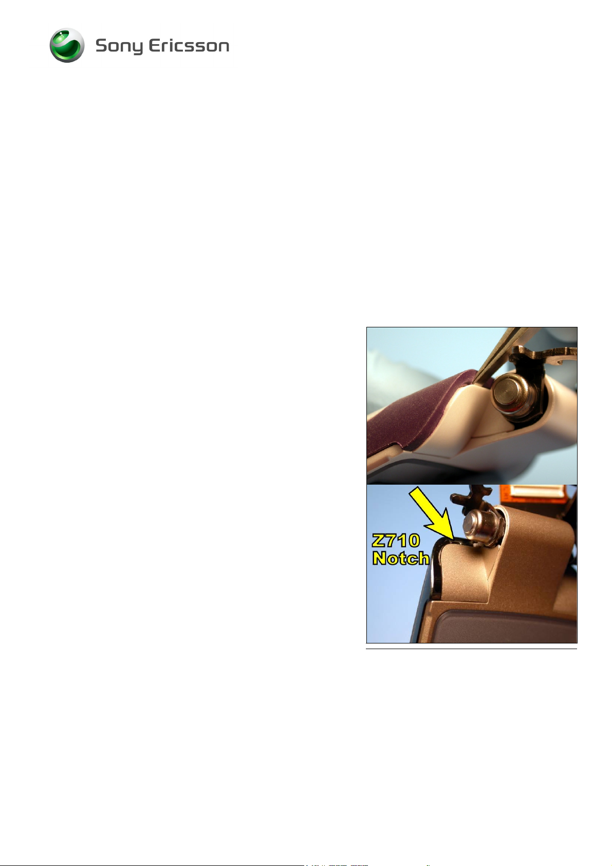
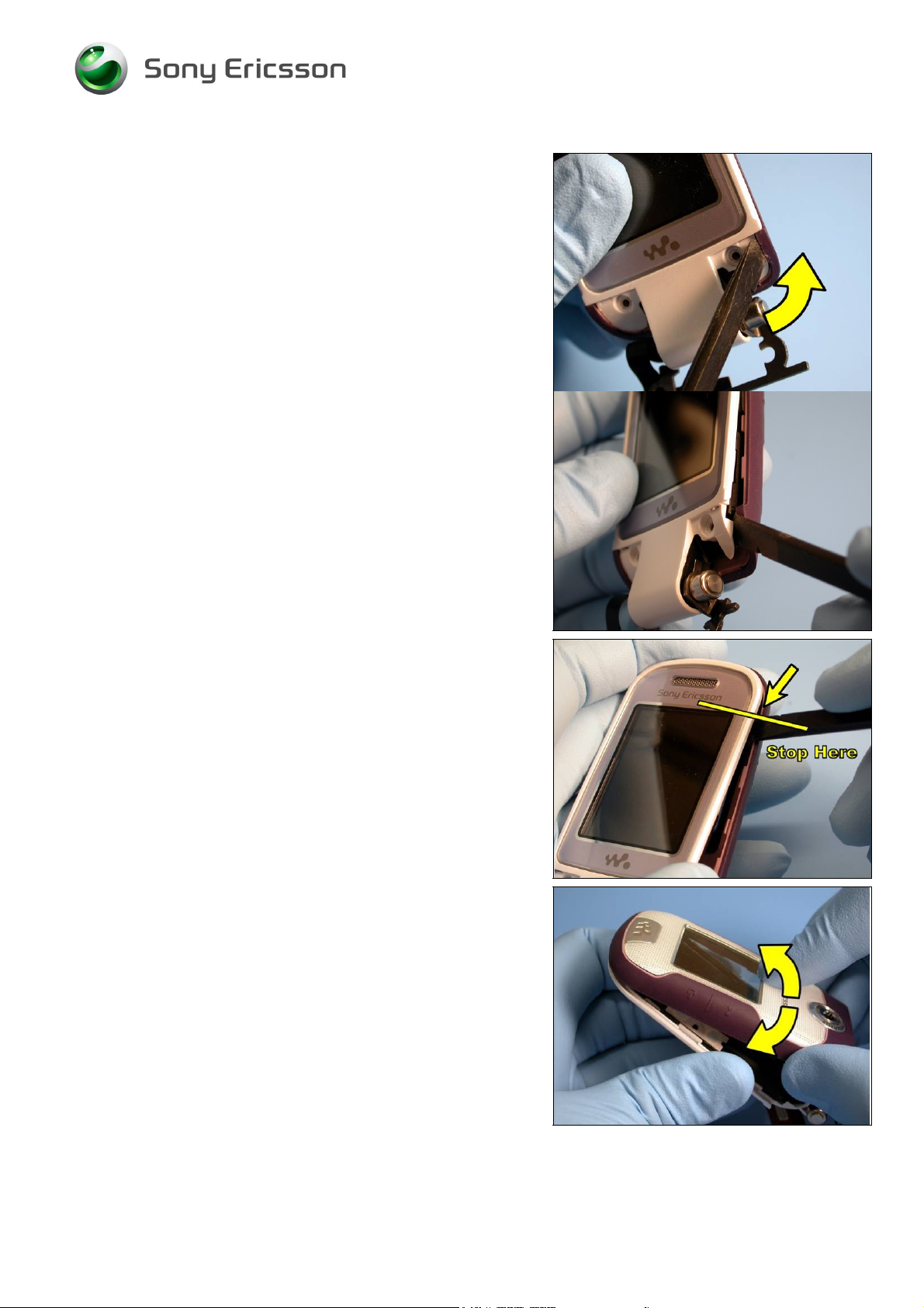
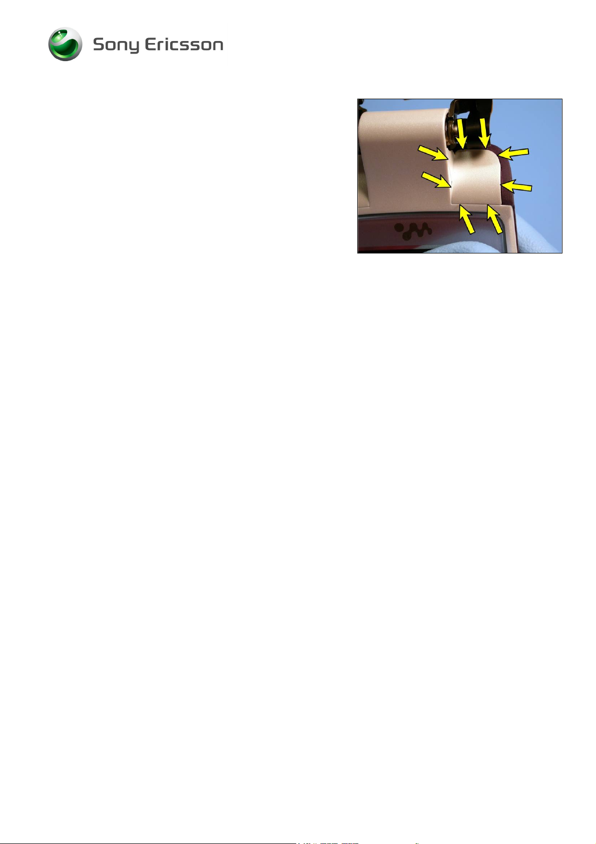
1. Insert the tip of a pair of style 2A tweezers behind
the flip screw cover under the metal hinge as
shown.
NOTE:
FOR Z710, THE SCREW COVER HAS A NOTCH THAT
YOU SHOULD PUT THE TIP OF YOUR TWEEZERS IN TO
PRY IT OFF
.
3/000 21-1/FEA 209 544/601 C
© Sony Ericsson Mobile Communications AB
13(101)
Page 14
Working Instruction, Mechanical
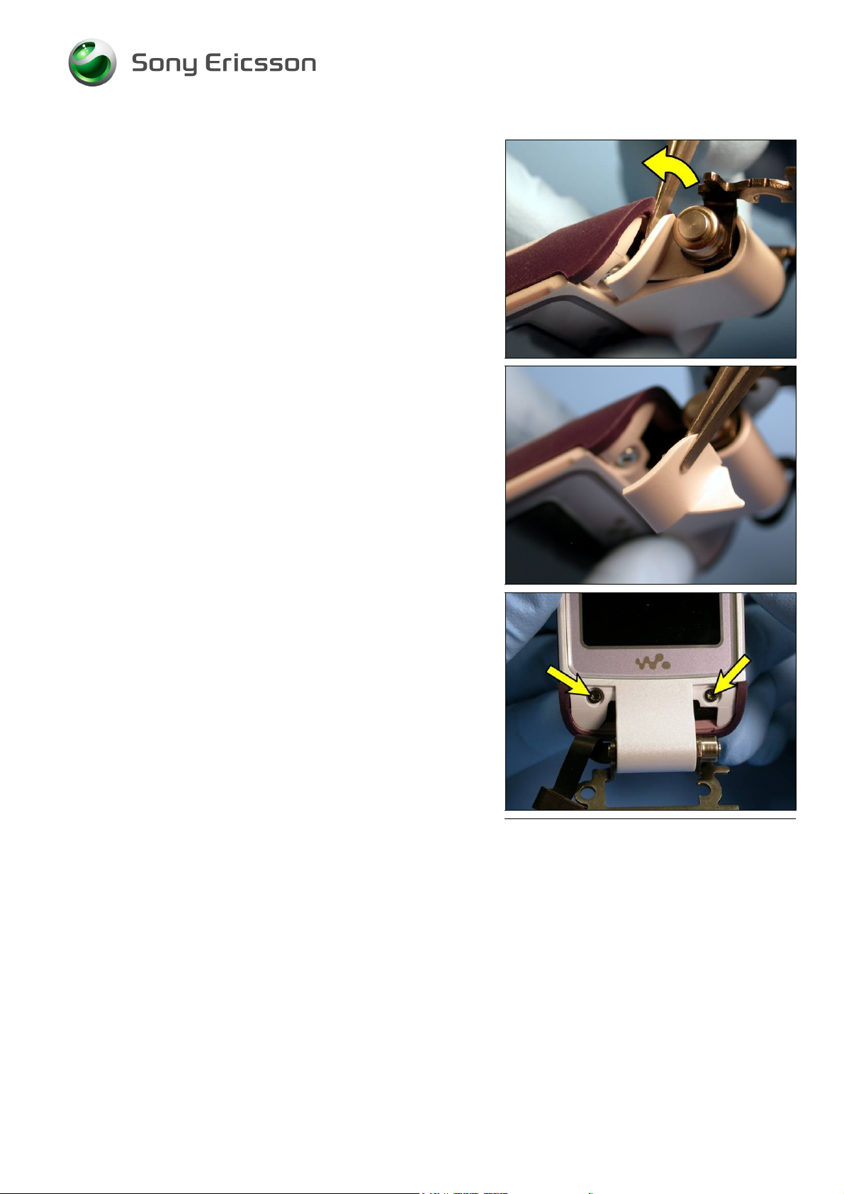
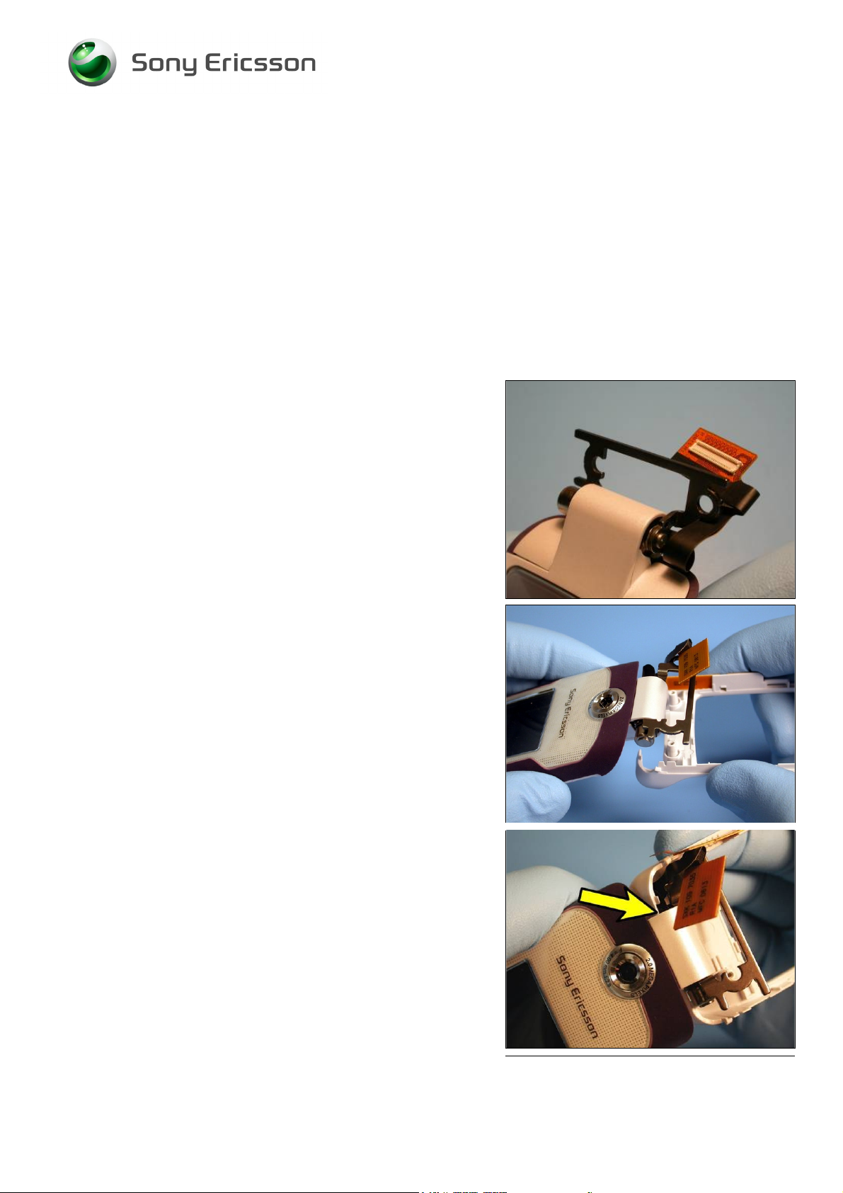
2. Rotate the tweezers away from the hinge to pry up
the flip screw cover.
3. When the flip screw cover has been freed, lift it
away from the phone with the tweezers. Repeat for
the other screw cover.
4. Remove the two screws using a torque driver and
T6 bit.
3/000 21-1/FEA 209 544/601 C
© Sony Ericsson Mobile Communications AB
14(101)
Page 15
Working Instruction, Mechanical
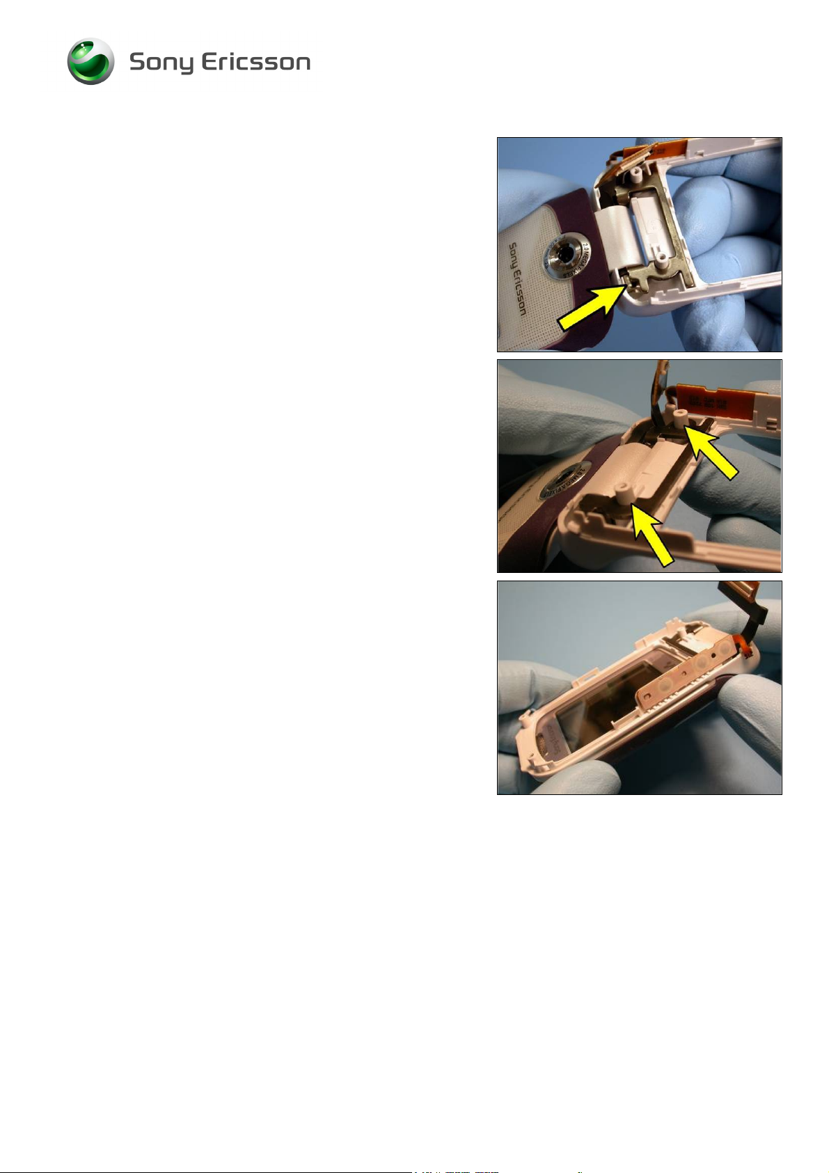
5. Insert the flat end of a nylon pointer between the
inner and outer flip covers near where the screw
was located. Pry away from the display to loosen
the outer flip cover.
6. Insert the flat end of the nylon pointer in the gap and
slide it along the seam until you reach the furthest
end of the display area.
7. Repeat the previous two steps on the other side of
the flip.
8. Slightly lift the freed end of the outer flip cover and
wiggle the outer flip cover side to side to free it from
the flip.
NOTE:
FOR W710, THE CAMERA RING MAY FALL OUT.
3/000 21-1/FEA 209 544/601 C
© Sony Ericsson Mobile Communications AB
15(101)
Page 16
Working Instruction, Mechanical
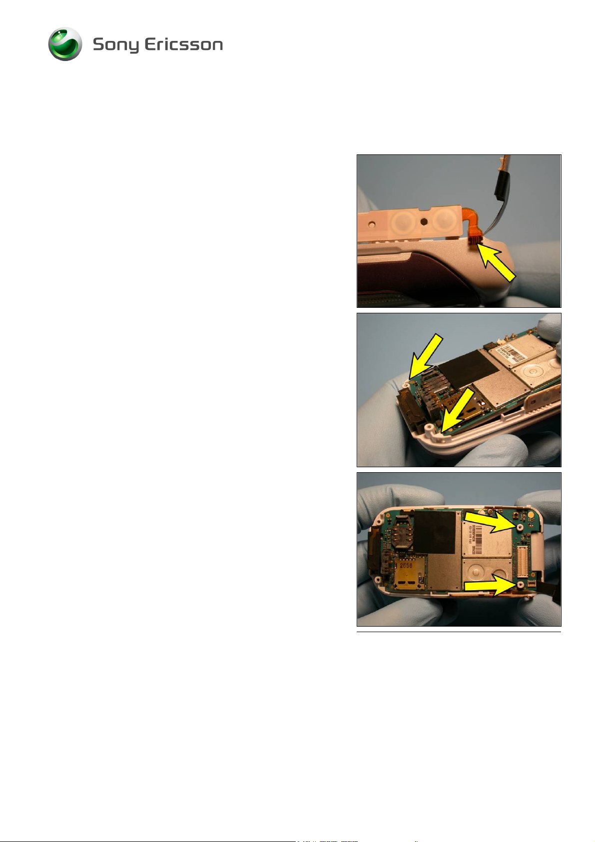
2.2.3 Inner Flip Cover Removal
All of the sections of the flip portion disassembly preceding this section must be performed in
sequential order before the steps listed below can be performed.
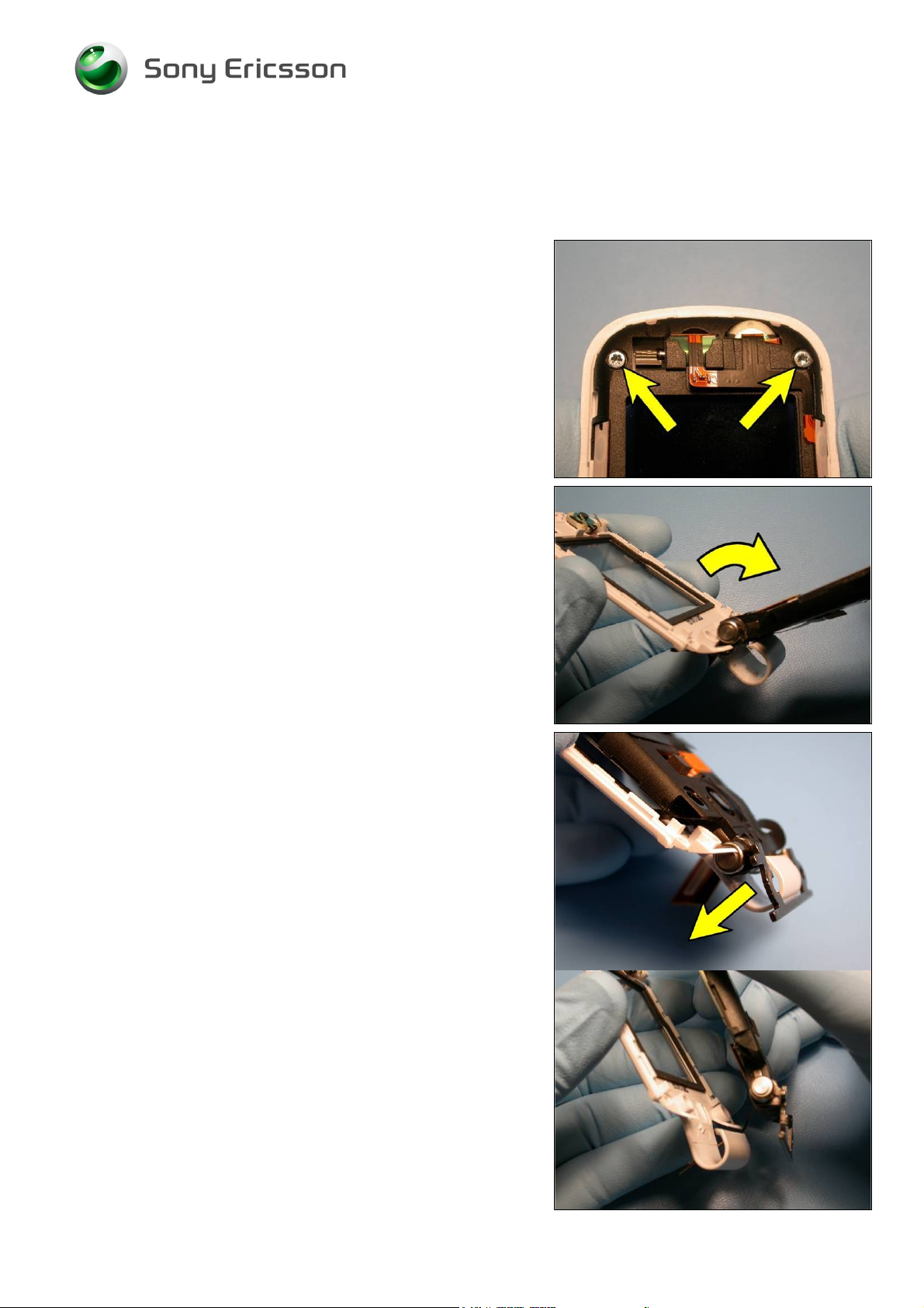
1. Remove the two screws indicated with a torque
driver and T6 bit.
2. Rotate the inner flip cover ~120 degrees from the flip
frame as shown.
3. Rotate the inner flip cover back down against the flip
frame and pull the hinge cover portion of the inner
flip cover through the opening between the hinge
and the metal hinge arm as shown.
NOTE!
BE CAREFUL TO NOT DAMAGE THE MAIN FLEX FILM
ASSEMBLY
.
3/000 21-1/FEA 209 544/601 C
© Sony Ericsson Mobile Communications AB
16(101)
Page 17
Working Instruction, Mechanical
3 Reassembly
3.1 Flip Portion Reassembly
The following subsections make up the “Flip Portion Reassembly” procedure. These subsections are
arranged in the order that they must be performed to properly reassemble the flip portion of this
product
3.1.1 Inner Flip Cover Installation
1. Verify that the receiver is installed in the inner flip
cover.
2. Make sure the camera, display, magnet, and
vibrator are installed in the flip frame.
3. Position the flex film on the camera side of the flip
assembly.
3/000 21-1/FEA 209 544/601 C
© Sony Ericsson Mobile Communications AB
17(101)
Page 18
Working Instruction, Mechanical
4. Push the hinge cover portion of the inner flip cover
through the opening between the hinge and the
hinge arm as shown.
NOTE!
BE CAREFUL TO NOT DAMAGE THE MAIN FLEX FILM
ASSEMBLY
.
5. Slide the inner flip cover over the hinge as shown.
6. Mate the inner flip cover and flip frame assembly so
that the features between the two components mesh
properly.
7. While holding the flip frame and inner flip cover
together, install two 1.6MM X 4.5MM screws where
shown with a T6 bit and torque driver set to 17
N*cm.
3/000 21-1/FEA 209 544/601 C
© Sony Ericsson Mobile Communications AB
18(101)
Page 19
Working Instruction, Mechanical
NOTE! AVOID OVERSTRESSING THE FLEX FILM WHEN
REPOSITIONING IT
THE FLEX FILM CAN OCCUR
8. Position the flex film to the display side of the flip
assembly
. NON-VISIBLE DAMAGE TO
.
3.1.2 Outer Flip Cover Installation
All of the sections of the flip portion reassembly preceding this section must be performed in
sequential order before the steps listed below can be performed.
1. Make sure the main flex film assembly is connected
to the display assembly and flip flex film.
2. W710 only – Install the camera ring on the flip
frame as shown. Make sure the alignment peg goes
in the alignment hole.
3/000 21-1/FEA 209 544/601 C
© Sony Ericsson Mobile Communications AB
19(101)
Page 20
Working Instruction, Mechanical
3. Position the main flex film assembly behind the
hinge arm and form the loop shape shown.
NOTE!
AVOID OVERSTRESSING THE FLEX FILM WHEN
POSITIONING IT IN THE
VISIBLE DAMAGE TO THE FLEX FILM CAN OCCUR.
“LOOP” SHAPE. NON-
4. Rotate the hinge to the closed position.
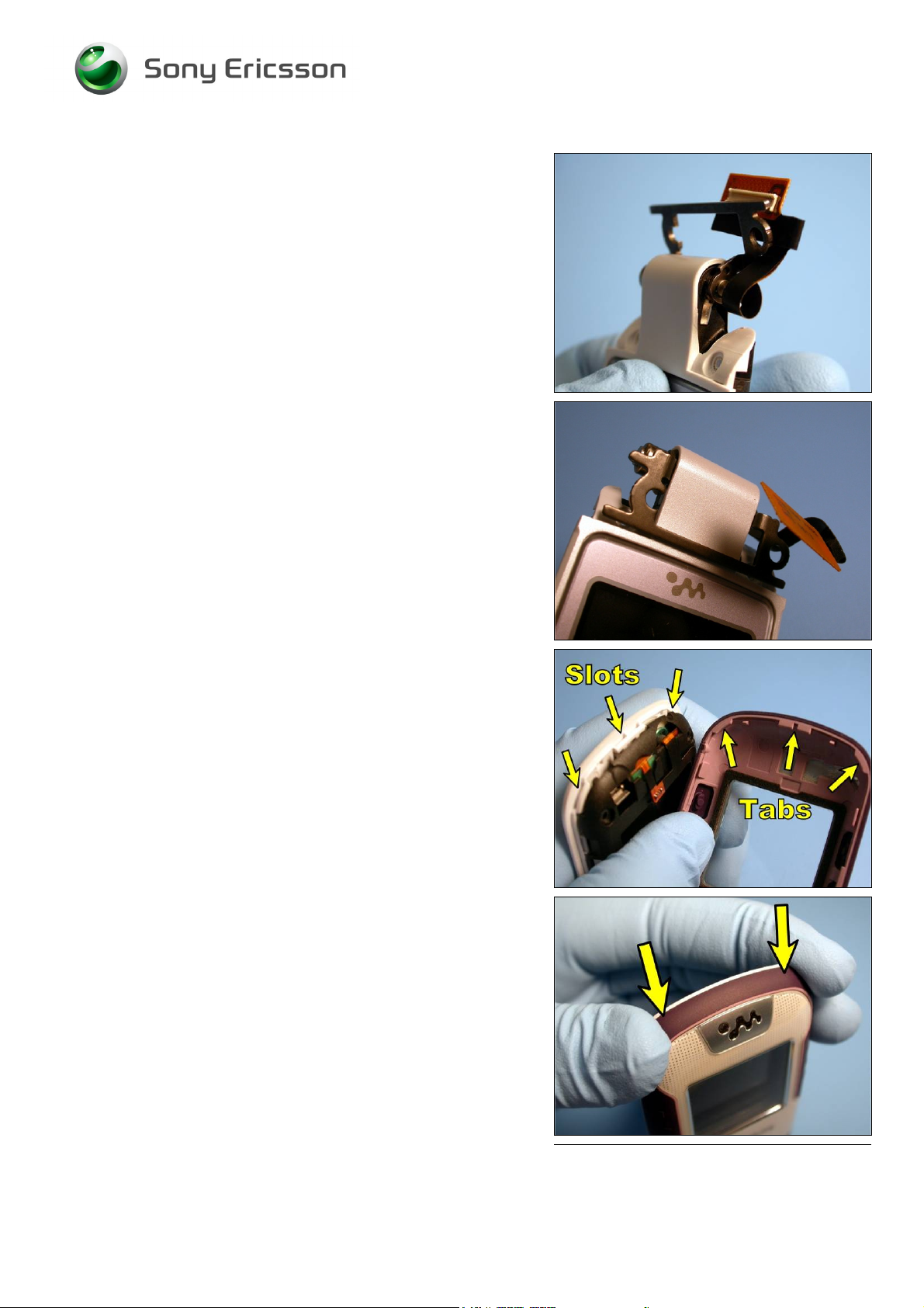
5. Position the outer flip cover over the end of the flip
so that the alignment tabs on the outer flip cover line
up with the slots on the end of the flip assembly.
6. Press the end of the outer flip cover toward the
hinge until the seam along the end of the flip is flush.
3/000 21-1/FEA 209 544/601 C
© Sony Ericsson Mobile Communications AB
20(101)
Page 21
Working Instruction, Mechanical
7. Press the outer flip cover down onto the flip and
snap the seam along each edge of the flip assembly
together.
NOTE!
YOU MAY NEED TO PRESS IN ON THE SIDES OF
THE OUTER FLIP COVER TO GET THE SEAMS
ALONG THE SIDE OF THE FLIP TO MATE
TOGETHER AS THEY SHOULD
.
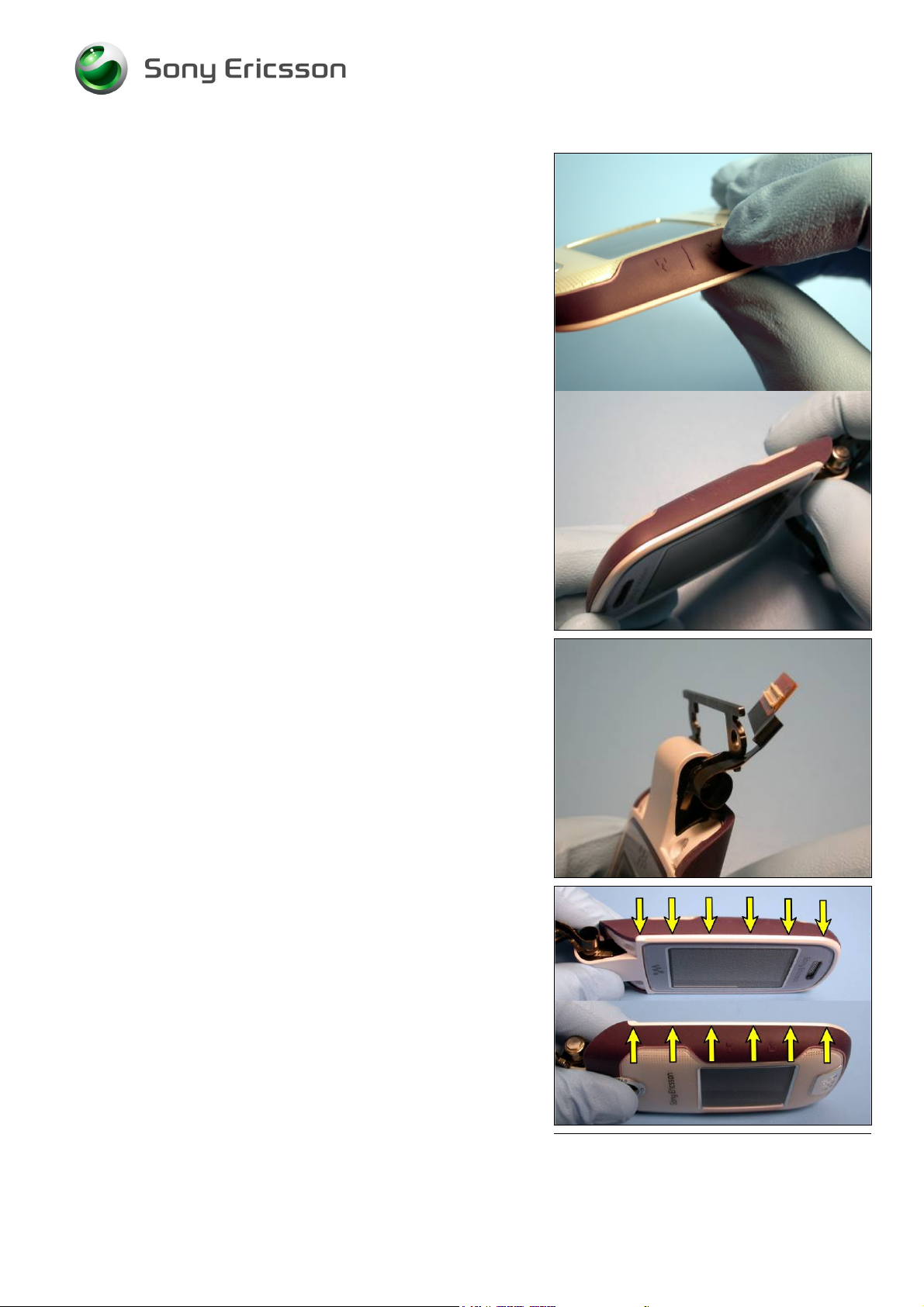
8. Rotate the hinge to the open position.
9. Reposition the main flex film assembly behind the
hinge arm so it is held in the loop shape shown.
NOTE!
AVOID OVERSTRESSING THE FLEX FILM WHEN
POSITIONING IT IN THE “LOOP” SHAPE. NON-
VISIBLE DAMAGE TO THE FLEX FILM CAN OCCUR.
10. Hold the flip assembly together and inspect to make
sure the seam is flush all the way around.
3/000 21-1/FEA 209 544/601 C
© Sony Ericsson Mobile Communications AB
21(101)
Page 22
Working Instruction, Mechanical
11. Install two 1.6MM X 5.1MM screws using a T6 bit
and torque driver set to 17 N*cm.
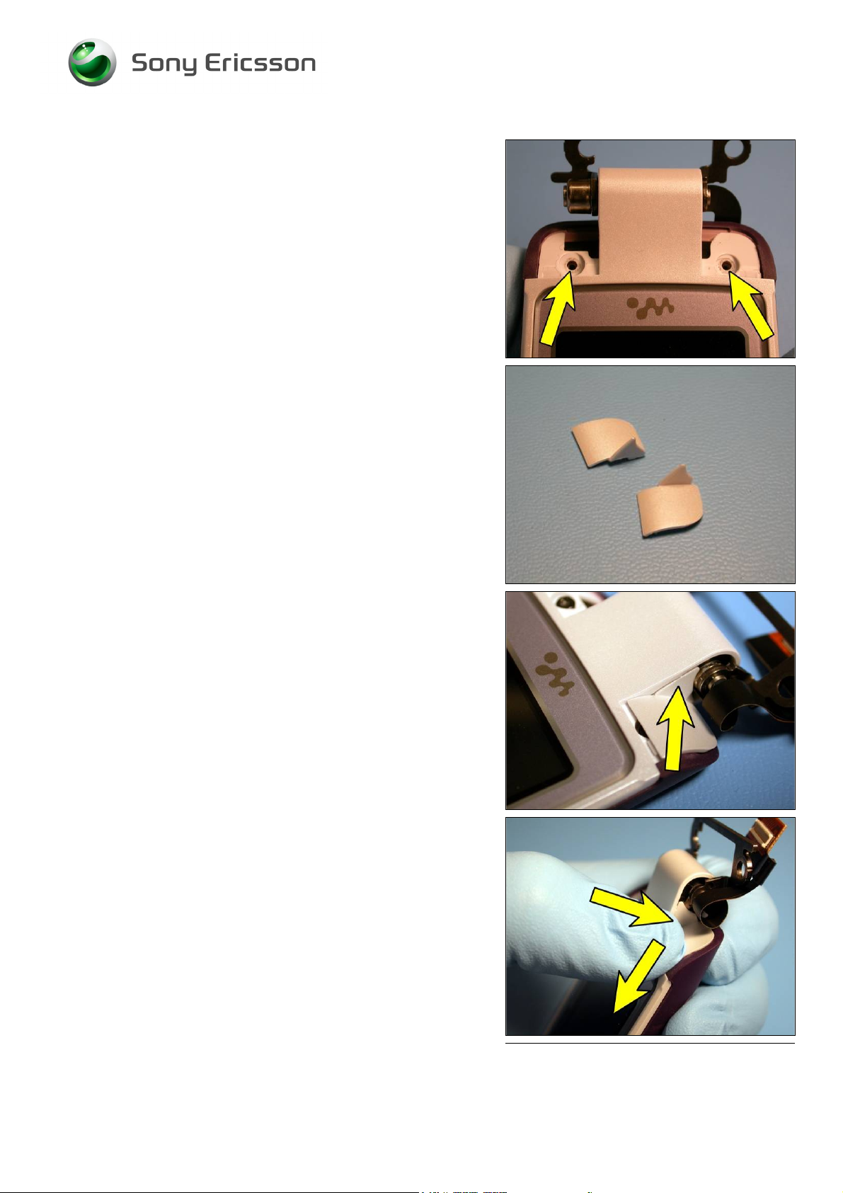
12. Obtain two new flip screw covers.
13. Remove the protective covering from a new flip
screw cover and using style 2A tweezers, position
the screw cover so that its flange inserts in the
corresponding area under the hinge as shown.
14. Press in and down so that the screw cover slides
slightly toward the inner flip cover and seats itself.
3/000 21-1/FEA 209 544/601 C
© Sony Ericsson Mobile Communications AB
22(101)
Page 23
Working Instruction, Mechanical
15. Make sure the screw cover doesn’t have gaps
around it and that it is fully seated into place.
16. Press on the screw cover for 15 seconds so the a
good adhesive bond between the screw cover and
the inner flip cover is formed
17. Repeat for the other screw cover.
3/000 21-1/FEA 209 544/601 C
© Sony Ericsson Mobile Communications AB
23(101)
Page 24
Working Instruction, Mechanical
3.2 Base Portion Reassembly
The following subsections make up the “Base Portion Reassembly” procedure. These subsections
are arranged in the order that they must be performed to properly reassemble the base portion of this
product.
3.2.1 Perform Flip Portion Reassembly
The flip portion of this phone must be reassembled before the base portion reassembly procedure
can be performed.
3.2.2 Inner Base Cover Installation
1. Open the metal hinge and position the main flex film
assembly behind the hinge so it is held in the loop
shape shown.
2. Orient the inner base cover to the flip assembly as
shown.
NOTE! Be careful to not damage the main flex film
assembly when assembling the inner base
cover to the flip.
3. Work the looped portion of the flex film into its cavity
in the inner base cover so that the flex film does not
get caught by the indicated corner of the inner base
cover.
3/000 21-1/FEA 209 544/601 C
© Sony Ericsson Mobile Communications AB
24(101)
Page 25
Working Instruction, Mechanical
4. Insert the other side of the hinge into its cavity in the
inner base cover.
5. Work the metal arm of the hinge down onto the inner
base cover so that the two screw bosses pass
through the corresponding holes in the hinge arm.
6. Close the flip and base portions of the phone.
3/000 21-1/FEA 209 544/601 C
© Sony Ericsson Mobile Communications AB
25(101)
Page 26
Working Instruction, Mechanical
3.2.3 Circuit Board Installation
All of the sections of the base portion reassembly preceding this section must be performed in
sequential order before the steps listed below can be performed.
1. Using style 2A tweezers, position the board
connection end of the side key flex film assembly
out of the way as indicated.
2. Slide the system connector end of the circuit board
into the inner base cover so that the board is under
the two indicated alignment tabs.
3. Lay the circuit board down on the inner base cover.
Make sure the screw bosses go through the
corresponding opening in the circuit board.
3/000 21-1/FEA 209 544/601 C
© Sony Ericsson Mobile Communications AB
26(101)
Page 27
Working Instruction, Mechanical
4. Make sure the black portion of the side key flex’s
board connector is rotated towards the side key flex
film so that it forms a 90 degree angle to the circuit
board.
NOTE! AVOID OVERSTRESSING THE SIDE KEY FLEX FILM
WHEN POSITIONING IT IN ITS CIRCUIT BOARD
CONNECTOR
FLEX FILM CAN OCCUR
. NON-VISIBLE DAMAGE TO THE
.
5. Using style 2A tweezers, insert the side key flex film
assembly into its connector until the notches cannot
be seen.
6. Rotate the black portion of the side key flex’s board
connector back down onto the circuit board as
shown.
3/000 21-1/FEA 209 544/601 C
© Sony Ericsson Mobile Communications AB
27(101)
Page 28
Working Instruction, Mechanical
7. Plug the main flex film assembly into its board
connector.
8. Look for a liquid intrusion indicator in the location
shown. If an indicator is not present, obtain a new
one and place it where shown.
3/000 21-1/FEA 209 544/601 C
© Sony Ericsson Mobile Communications AB
28(101)
Page 29
Working Instruction, Mechanical
3.2.4 Antenna Cover Installation
All of the sections of the base portion reassembly preceding this section must be performed in
sequential order before the steps listed below can be performed.
1. Insert the antenna cover’s large flat tab under the
circuit board as indicated.
2. While pushing the antenna cover toward the circuit
board, rotate the antenna cover so that its two tabs
insert under the inner base cover.
3/000 21-1/FEA 209 544/601 C
© Sony Ericsson Mobile Communications AB
29(101)
Page 30
Working Instruction, Mechanical
3.2.5 Outer Base Cover Installation
All of the sections of the base portion reassembly preceding this section must be performed in
sequential order before the steps listed below can be performed.
1. Make sure the volume and camera keys are in the
outer base cover as shown.
2. Make sure the phone lock key is in the position
shown.
3. If the rear speaker box is not installed, insert it into
the outer base cover as shown.
3/000 21-1/FEA 209 544/601 C
© Sony Ericsson Mobile Communications AB
30(101)
Page 31

Working Instruction, Mechanical
4. Hold the outer base cover as shown.
5. Hold the rest of the phone as shown. Be sure to hold
the antenna cover in place.
3/000 21-1/FEA 209 544/601 C
© Sony Ericsson Mobile Communications AB
31(101)
Page 32

Working Instruction, Mechanical
6. Insert the antenna cover’s large latch into the
corresponding opening in the outer base cover.
7. Make sure the side key flex film assembly is
positioned above the volume and camera keys.
3/000 21-1/FEA 209 544/601 C
© Sony Ericsson Mobile Communications AB
32(101)
Page 33

Working Instruction, Mechanical
8. Rotate the two halves together. If any keys are out
of place the two halves will not easily go together so
do not force the two halves together.
9. Snap the outer base cover onto the inner base
cover.
10. Make sure the antenna cover is seated properly.
11. Make sure the volume key, the camera key, and
phone lock key respond correctly.
3/000 21-1/FEA 209 544/601 C
© Sony Ericsson Mobile Communications AB
33(101)
Page 34

Working Instruction, Mechanical
12. Verify that the RF plug is installed in the outer base
cover.
13. Install two 1.6MM X 12MM screws at the locations
indicated using a T6 bit and torque driver set to 23
N*cm.
14. Install two 1.6MM X 5.1MM screws at the locations
indicated using a T6 bit and torque driver set to 17
N*cm.
3/000 21-1/FEA 209 544/601 C
© Sony Ericsson Mobile Communications AB
34(101)
Page 35

Working Instruction, Mechanical
3.2.6 Battery Installation
All of the sections of the base portion reassembly preceding this section must be performed in
sequential order before the steps listed below can be performed.
1. Obtain a battery and position it so that the battery’s
contact pads are aligned to the battery contacts in
the phone’s battery cavity.
2. Press the battery into the battery cavity.
3/000 21-1/FEA 209 544/601 C
© Sony Ericsson Mobile Communications AB
35(101)
Page 36

Working Instruction, Mechanical
3.2.7 Battery Door Installation
All of the sections of the base portion reassembly preceding this section must be performed in
sequential order before the steps listed below can be performed.
1. Make sure the battery latch has been moved in the
direction indicated by the triangle that is on the latch
as shown.
2. Insert the two battery door tabs indicated into the
two slots in the outer base cover.
3. Lower the battery door onto the outer base cover
and snap it into place.
4. Press the latch on the battery door toward the hinge
as shown.
3/000 21-1/FEA 209 544/601 C
© Sony Ericsson Mobile Communications AB
36(101)
Page 37

Working Instruction, Mechanical
4 Part Replacement
NOTE: BE SURE TO USE REPLACEMENT PARTS DESIGNED FOR THE PARTICULAR MODEL OF PHONE THAT
YOU ARE WORKING WITH. SOME PARTS ARE SHARED BETWEEN W710 AND Z710, BUT NOT ALL.
4.1 Battery Door
Perform the disassembly procedure from section 2.1.1
Obtain a new battery door.
Perform the reassembly procedure from section 3.2.7
4.2 Phone Label
4.2.1 Label Removal
Perform sections 2.1.1-2.1.2 of the base portion
disassembly procedure.
1. Before removing the label, print a new label.
NOTE!
NOTE! LABELS ONLY HAVE TO BE REMOVED FROM THE
NOTE!
NOTE!
THE TEXT ON THE NEW LABEL MUST BE FULLY
READABLE AND ALL BARCODES MUST BE
SCANNABLE
PHONE IF THERE ARE ALREADY TWO OR MORE
LABELS ON THE PHONE
HEATING UP THE OLD LABEL(S) WITH A HOT AIR
DEVICE MAY MAKE REMOVING THEM EASIER
2. Carefully peel the old label from the bottom of the
battery cavity.
MAKE SURE THAT ALL ADHESIVE RESIDUE IS
REMOVED
RESIDUE WITH ALCOHOL AND A LINT
.
.
.
. CAREFULLY CLEAN OFF ANY REMAINING
-FREE CLOTH.
3/000 21-1/FEA 209 544/601 C
© Sony Ericsson Mobile Communications AB
37(101)
Page 38

Working Instruction, Mechanical
4.2.2 Label Installation
NOTE! NO MORE THAN TWO LABELS ARE ALLOWED
STACKED ON TOP OF EACH OTHER IN THE BATTERY
CAVITY
PRESENT, PERFORM THE LABEL REMOVAL
PROCEDURE BEFORE CONTINUING
1. If a new label has not been created yet, then do so
at this time.
NOTE! WHEN INSTALLING A NEW LABEL, BE VERY CAREFUL
TO AVOID TOUGHING THE CONTACTS OF THE
BATTERY CONNECTOR WITH THE ADHESIVE SIDE OF
THE LABEL
2. Using tweezers, orient the label as shown and place
the end of the label that is adjacent to the battery
contacts first. Then roll the rest of the label down
onto the floor of the battery cavity.
. IF THERE ARE ALREADY TWO LABELS
.
.
3. Once the label is correctly positioned, carefully
smooth it into place.
Starting at section 3.2.6, perform the remainder of the base
portion reassembly procedure.
3/000 21-1/FEA 209 544/601 C
© Sony Ericsson Mobile Communications AB
38(101)
Page 39

Working Instruction, Mechanical
4.3 Outer Base Cover
Perform sections 2.1.1-2.1.3 of the base portion
disassembly procedure.
1. Make sure the phone lock key is in the position
shown. Remove the speaker box by gripping it near
the antenna and pulling it straight out of the outer
base cover.
2. Use style 2A tweezers to remove the volume key
from the outer base cover.
3. Use style 2A tweezers to remove the camera key
from the outer base cover.
3/000 21-1/FEA 209 544/601 C
© Sony Ericsson Mobile Communications AB
39(101)
Page 40

Working Instruction, Mechanical
4. Use style 2A tweezers to pull the RF Plug from its
hole in the outer base cover.
5. Insert the flat end of a nylon pointer where shown
and twist it to dislodge the phone lock key, then use
style 2A tweezers to remove it from the outer base
cover.
3/000 21-1/FEA 209 544/601 C
© Sony Ericsson Mobile Communications AB
40(101)
Page 41

Working Instruction, Mechanical
6. Use style 2A tweezers to dislodge the end of the IR
window closest to the system connector opening in
the outer base cover.
7. With a nylon pointer, push on the IR window from
the outside of the outer base cover to remove it from
its hole in the outer base cover.
8. Obtain a new outer base cover.
3/000 21-1/FEA 209 544/601 C
© Sony Ericsson Mobile Communications AB
41(101)
Page 42

Working Instruction, Mechanical
9. Using style 2A tweezers, position the IR window as
shown so that the edge indicated goes into its hole
in the outer base cover first.
10. Press on the IR window so that it snaps into place in
the outer base cover. Make sure the ends of the IR
window snap behind the tabs as indicated.
3/000 21-1/FEA 209 544/601 C
© Sony Ericsson Mobile Communications AB
42(101)
Page 43

Working Instruction, Mechanical
11. Use style 2A tweezers to position the phone lock
key so that the edge indicated goes behind the
retainer tab.
12. Press on the phone lock key so that it snaps into
place in the outer base cover.
3/000 21-1/FEA 209 544/601 C
© Sony Ericsson Mobile Communications AB
43(101)
Page 44

Working Instruction, Mechanical
13. From the outside of the outer base cover, insert the
RF plug into its hole so that the outer surface of the
plug is flush with the outer surface of the outer base
cover.
14. Using style 2A tweezers, insert the camera key into
the outer base cover in the orientation shown.
3/000 21-1/FEA 209 544/601 C
© Sony Ericsson Mobile Communications AB
44(101)
Page 45

Working Instruction, Mechanical
15. Using style 2A tweezers, insert the volume key into
the outer base cover in the orientation shown.
16. Make sure the phone lock key is in the position
shown. Grip the speaker box near the antenna and
insert it straight into the outer base cover. If it does
not go in straight, it may knock out the RF plug or
volume key.
3/000 21-1/FEA 209 544/601 C
© Sony Ericsson Mobile Communications AB
45(101)
Page 46

Working Instruction, Mechanical
17. Perform the label installation procedure
Starting at section 3.2.5, perform the remainder of the base
portion reassembly procedure.
4.4 Rear Speaker Box
Perform sections 2.1.1-2.1.3 of the base portion
disassembly procedure.
1. Make sure the phone lock key is in the position
shown.
2. Remove the speaker box by gripping it near the
antenna and pulling it straight out of the outer base
cover.
3/000 21-1/FEA 209 544/601 C
© Sony Ericsson Mobile Communications AB
46(101)
Page 47

Working Instruction, Mechanical
3. Obtain a new rear speaker box, rear speaker, rear
speaker adhesive ring, and rear speaker cloth.
4. Remove the adhesive ring from its protective
backing and place it into the rear speaker cavity in
the rear speaker box where indicated.
5. Place the rear speaker into the rear speaker cavity
in the rear speaker box and press on the edges to
make sure it sticks well.
6. Remove the protective cover from the rear speaker
flex and wrap it around the rear speaker box as
shown. Make sure the alignment pegs indicated go
through the alignment holes in the flex.
3/000 21-1/FEA 209 544/601 C
© Sony Ericsson Mobile Communications AB
47(101)
Page 48

Working Instruction, Mechanical
7. Remove the rear speaker cloth from its protective
backing and place it over the rear speaker in the
orientation shown. The final location is highlighted.
8. Make sure the phone lock key is in the position
shown.
9. Grip the speaker box near the antenna and insert it
straight into the outer base cover. If it does not go in
straight, it may knock out the RF plug or volume key.
Starting at section 3.2.5, perform the remainder of the base
portion reassembly procedure.
3/000 21-1/FEA 209 544/601 C
© Sony Ericsson Mobile Communications AB
48(101)
Page 49

Working Instruction, Mechanical
4.5 Rear Speaker Cloth
Perform sections 2.1.1-2.1.3 of the base portion
disassembly procedure.
1. Make sure the phone lock key is in the position
shown.
2. Remove the speaker box by gripping it near the
antenna and pulling it straight out of the outer base
cover.
3. Use style 2A tweezers to pull the rear speaker cloth
off of the rear speaker box. Clean off any adhesive
residue with alcohol and a lint free wipe.
NOTE!
AVOID DAMAGING THE REAR SPEAKER.
3/000 21-1/FEA 209 544/601 C
© Sony Ericsson Mobile Communications AB
49(101)
Page 50

Working Instruction, Mechanical
4. Obtain a new rear speaker cloth and remove the
protective film from it.
5. Position the cloth onto the rear speaker box in the
orientation shown. The final location of the cloth is
highlighted.
6. Firmly press on the edges of the cloth to make sure
it sticks well.
3/000 21-1/FEA 209 544/601 C
© Sony Ericsson Mobile Communications AB
50(101)
Page 51

Working Instruction, Mechanical
7. Make sure the phone lock key is in the position
shown.
8. Grip the speaker box near the antenna and insert it
straight into the outer base cover. If it does not go in
straight, it may knock out the RF plug or volume key.
Starting at section 3.2.5, perform the remainder of the base
portion reassembly procedure.
3/000 21-1/FEA 209 544/601 C
© Sony Ericsson Mobile Communications AB
51(101)
Page 52

Working Instruction, Mechanical
4.6 Rear Speaker
Perform sections 2.1.1-2.1.3 of the base portion
disassembly procedure.
1. Make sure the phone lock key is in the position
shown.
2. Remove the speaker box by gripping it near the
antenna and pulling it straight out of the outer base
cover.
3. The rear speaker flex is adhered to the rear speaker
box. Use style 2A tweezers to pull the rear speaker
flex off of the rear speaker box.
NOTE!
AVOID DAMAGING THE REAR SPEAKER BOX.
4. Use style 2A tweezers to remove the rear speaker
from the rear speaker box by inserting style 2A
tweezers at the location shown and prying the
speaker free.
NOTE!
3/000 21-1/FEA 209 544/601 C
AVOID DAMAGING THE REAR SPEAKER BOX.
© Sony Ericsson Mobile Communications AB
52(101)
Page 53

Working Instruction, Mechanical
5. Using style 2A tweezers, remove the old adhesive
ring. Use alcohol and a lint-free wipe to remove any
remaining adhesive residue.
NOTE! Be careful to not damage the rear speaker
box.
6. Obtain a new rear speaker, rear speaker adhesive
ring, and rear speaker cloth.
7. Remove the adhesive ring from its protective
backing and place it into the rear speaker cavity in
the rear speaker box where indicated.
8. Place the rear speaker into the rear speaker cavity
in the rear speaker box and press on the edges to
make sure it sticks well.
3/000 21-1/FEA 209 544/601 C
© Sony Ericsson Mobile Communications AB
53(101)
Page 54

Working Instruction, Mechanical
9. Remove the protective cover from the rear speaker
flex and wrap it around the rear speaker box as
shown. Make sure the alignment pegs indicated go
through the alignment holes in the flex.
10. Remove the protective film from the rear speaker
cloth and position the cloth onto the rear speaker
box in the orientation shown. The final location of
the cloth is highlighted.
11. Firmly press on the edges of the cloth to make sure
it sticks well.
3/000 21-1/FEA 209 544/601 C
© Sony Ericsson Mobile Communications AB
54(101)
Page 55

Working Instruction, Mechanical
12. Make sure the phone lock key is in the position
shown.
13. Grip the speaker box near the antenna and insert it
straight into the outer base cover. If it does not go in
straight, it may knock out the RF plug or volume key.
Starting at section 3.2.5, perform the remainder of the base
portion reassembly procedure.
3/000 21-1/FEA 209 544/601 C
© Sony Ericsson Mobile Communications AB
55(101)
Page 56

Working Instruction, Mechanical
4.7 Volume Key
Perform sections 2.1.1-2.1.3 of the base portion
disassembly procedure.
1. Make sure the phone lock key is in the position
shown.
2. Remove the speaker box by gripping it near the
antenna and pulling it straight out of the outer base
cover.
3. Use style 2A tweezers to remove the old volume key
by lifting it out of the outer base cover.
3/000 21-1/FEA 209 544/601 C
© Sony Ericsson Mobile Communications AB
56(101)
Page 57

Working Instruction, Mechanical
4. Obtain a new volume key and insert it into the outer
base cover so that it is oriented as shown.
5. Make sure the phone lock key is in the position
shown.
6. Grip the speaker box near the antenna and insert it
straight into the outer base cover. If it does not go in
straight, it may knock out the RF plug or volume key.
Starting at section 3.2.5, perform the remainder of the base
portion reassembly procedure.
3/000 21-1/FEA 209 544/601 C
© Sony Ericsson Mobile Communications AB
57(101)
Page 58

Working Instruction, Mechanical
4.8 Camera key
Perform sections 2.1.1-2.1.3 of the base portion
disassembly procedure.
1. Use style 2A tweezers to remove the old camera
key by lifting it out of the outer base cover.
2. Obtain a new camera key and insert it into the outer
base cover so that it is oriented as shown.
Starting at section 3.2.5, perform the remainder of the base
portion reassembly procedure.
3/000 21-1/FEA 209 544/601 C
© Sony Ericsson Mobile Communications AB
58(101)
Page 59

Working Instruction, Mechanical
4.9 Phone Lock Key
Perform sections 2.1.1-2.1.3 of the base portion
disassembly procedure.
1. Make sure the phone lock key is in the position
shown.
2. Remove the speaker box by gripping it near the
antenna and pulling it straight out of the outer base
cover.
3. Insert the flat end of a nylon pointer where shown
and twist it to dislodge the phone lock key, then use
style 2A tweezers to remove it from the outer base
cover.
3/000 21-1/FEA 209 544/601 C
© Sony Ericsson Mobile Communications AB
59(101)
Page 60

Working Instruction, Mechanical
4. Obtain a new phone lock key. Use style 2A tweezers
to position the phone lock key so that the edge
indicated goes behind the retainer tab.
5. Press on the phone lock key so that it snaps into
place in the outer base cover.
3/000 21-1/FEA 209 544/601 C
© Sony Ericsson Mobile Communications AB
60(101)
Page 61

Working Instruction, Mechanical
7. Make sure the phone lock key is in the position
shown.
8. Grip the speaker box near the antenna and insert it
straight into the outer base cover. If it does not go in
straight, it may knock out the RF plug or volume key.
Perform the reassembly procedure from section 3.2.5
4.10 Infrared Window
Perform sections 2.1.1-2.1.3 of the base portion
disassembly procedure.
1. Using style 2A tweezers, dislodge the end of the IR
window closest to the system connector opening in
the outer base cover.
2. With a nylon pointer, push on the IR window from
the outside of the outer base cover to remove it from
its hole in the outer base cover.
3/000 21-1/FEA 209 544/601 C
© Sony Ericsson Mobile Communications AB
61(101)
Page 62

Working Instruction, Mechanical
3. Obtain a new IR window.
4. Position the IR window as shown so that the edge
indicated goes into its hole in the outer base cover
first.
5. Press on the IR window so that it snaps into place in
the outer base cover. Make sure the ends of the IR
window snap behind the tabs as indicated.
Starting at section 3.2.5, perform the remainder of the base
portion reassembly procedure.
4.11 Antenna Cover
Perform sections 2.1.1-2.1.4 of the base portion disassembly procedure.
Obtain a new antenna cover.
Starting at section 3.2.4, perform the remainder of the base portion reassembly procedure.
3/000 21-1/FEA 209 544/601 C
© Sony Ericsson Mobile Communications AB
62(101)
Page 63

Working Instruction, Mechanical
4.12 SIM Tape
Perform sections 2.1.1-2.1.3 of the base portion
disassembly procedure.
1. Use style 2A tweezers to peel the SIM tape off the
shield can.
2. Obtain a new SIM tape.
3. Using tweezers, position the SIM tape as shown.
Line up the SIM tape with the shield can edges
indicated. The final location for the tape is
highlighted.
4. Rub over the surface of the SIM tape to make sure it
bonds well to the shield can.
Starting at section 3.2.5, perform the remainder of the base
portion reassembly procedure.
3/000 21-1/FEA 209 544/601 C
© Sony Ericsson Mobile Communications AB
63(101)
Page 64

Working Instruction, Mechanical
4.13 System Connector
Perform sections 2.1.1-2.1.5 of the base portion
disassembly procedure.
1. Grip the system connector on its ends and pull it
straight off of the circuit board.
2. Obtain a new system connector and orient it so that
the Bluetooth antenna is facing the same direction
as the SIM connector on the circuit board.
3. Slide the new system connector onto the edge of the
circuit board as shown.
Starting at section 3.2.3, perform the remainder of the base
portion reassembly procedure.
3/000 21-1/FEA 209 544/601 C
© Sony Ericsson Mobile Communications AB
64(101)
Page 65

Working Instruction, Mechanical
4.14 Keypad and Dome Array
4.14.1 Removal
Perform sections 2.1.1-2.1.5 of the base portion
disassembly procedure.
1. Insert one side of a pair of style 2A tweezers under
the dome array as shown.
NOTE! DO NOT PRY AGAINST THE CIRCUIT BOARD
WHEN TRYING TO GET THE LIFTING OF THE
CORNER OF THE DOME ARRAY AND KEYPAD
STARTED
2. Lift the tweezers so that the corner of both the dome
array and keypad lift up from the circuit board.
3. Pull the dome array/keypad assembly away from the
circuit board until the assembly is separated from
the circuit board.
4. Use alcohol and a lint free cloth to clean any
adhesive residue off of the circuit board, but be
careful to not damage any of the components on the
circuit board.
.
3/000 21-1/FEA 209 544/601 C
© Sony Ericsson Mobile Communications AB
65(101)
Page 66

Working Instruction, Mechanical
4.14.2 Installation
1. Obtain a new dome array and remove the protective
film from its adhesive.
2. Position the dome array on the circuit board so that
the two dome array holes indicated line up with
holes in the circuit board. Make sure the LEDs on
the circuit board line up with their holes in the dome
array.
3. Except for the keypad, reassemble the phone by
performing the reassembly procedures starting at
section 3.2.3
4. Obtain a new keypad and remove the protective film
from its adhesive
5. Insert the navigation key end of the keypad first as
shown.
6. Lay the keypad down into its cavity in the inner base
cover as shown. Make sure it is completely within its
cavity.
3/000 21-1/FEA 209 544/601 C
© Sony Ericsson Mobile Communications AB
66(101)
Page 67

Working Instruction, Mechanical
7. Make sure there is not a gap at the top of the
keypad.
8. Press down on the entire keypad surface for 30
seconds to make sure it sticks well.
9. Obtain a new flip bumper and remove it from its
protective backing.
10. Position the flip bumper in the flip bumper cavity in
the keypad. Make sure the flip bumper is completely
in its cavity and not hanging over the side.
11. Press on the flip bumper to make sure it sticks well.
3/000 21-1/FEA 209 544/601 C
© Sony Ericsson Mobile Communications AB
67(101)
Page 68

Working Instruction, Mechanical
12. Obtain a new co-brand label and remove it from its
protective backing.
13. Position the co-brand label in the co-brand label
cavity in the keypad. Make sure the co-brand label is
completely in its cavity and not hanging over the
side.
14. Press on the co-brand label to make sure it sticks
well.
No further reassembly is required.
3/000 21-1/FEA 209 544/601 C
© Sony Ericsson Mobile Communications AB
68(101)
Page 69

Working Instruction, Mechanical
4.15 Microphone Cloth
• Perform sections 2.1.1-2.1.5 of the base portion
disassembly procedure.
• Perform the Keypad and Dome Array removal
procedure
1. Using style 2A tweezers gently pull the microphone
cloth off of the microphone.
NOTE!
2. Obtain a new microphone cloth and remove the
3. Position the microphone cloth so that it lines up with
BE CAREFUL TO NOT DAMAGE THE MICROPHONE.
protective film from its adhesive.
the microphone. Press it into place on the
microphone so that a good bond is formed.
• Perform the Keypad and Dome Array installation
procedure.
• Starting at section 3.2.3, perform the remainder of the
base portion reassembly procedure.
3/000 21-1/FEA 209 544/601 C
© Sony Ericsson Mobile Communications AB
69(101)
Page 70

Working Instruction, Mechanical
4.16 Side Key Flex Assembly
Perform sections 2.1.1-2.1.3 of the base portion
disassembly procedure.
1. Insert the flat end of a nylon pointer between the
hinge cover and the portion of the flex film’s board
connector that overhangs the edge of the circuit
board.
2. Hold the circuit board in place and disconnect the
main flex film assembly from the circuit board by
twisting the nylon pointer as shown.
3. Rotate the black portion of the side key flex film’s
board connector 90 degrees toward the side key flex
film assembly.
4. Using style 2A tweezers, remove the connection
portion of the side key flex film from its connector
and position it on the outside of the phone as
indicated.
3/000 21-1/FEA 209 544/601 C
© Sony Ericsson Mobile Communications AB
70(101)
Page 71

Working Instruction, Mechanical
5. Pull the side key flex film assembly off its tab. Use
alcohol and a lint free cloth to remove any adhesive
residue from the tab.
6. Obtain a new side key flex film assembly and
remove the protective film from its adhesive.
7. Position the side key flex film assembly onto the
support plate as shown. Make sure the alignment
pegs go through the alignment holes.
8. Make sure the black portion of the side key flex’s
board connector is rotated towards the side key flex
film so that it forms a 90 degree angle to the circuit
board.
3/000 21-1/FEA 209 544/601 C
© Sony Ericsson Mobile Communications AB
71(101)
Page 72

Working Instruction, Mechanical
NOTE! AVOID OVERSTRESSING THE SIDE KEY FLEX FILM
WHEN POSITIONING IT IN ITS CIRCUIT BOARD
CONNECTOR
FLEX FILM CAN OCCUR
9. Using style 2A tweezers, insert the side key flex film
assembly into its connector until the notches cannot
be seen.
. NON-VISIBLE DAMAGE TO THE
.
10. Rotate the black portion of the side key flex’s board
connector back down onto the circuit board as
shown.
11. Plug the main flex film assembly into its board
connector.
Starting at section 3.2.5, perform the remainder of the base
portion reassembly procedure.
3/000 21-1/FEA 209 544/601 C
© Sony Ericsson Mobile Communications AB
72(101)
Page 73

Working Instruction, Mechanical
4.17 Co-Brand Label and Flip Bumper
No disassembly required.
1. Insert the tip of Style 2A tweezers under both the flip
bumper and co-brand label as shown.
NOTE!
BE CAREFUL TO NOT DAMAGE THE INNER BASE
COVER WITH THE TWEEZERS
INSTEAD IF NECESSARY
. USE A PRY TOOL
.
2. Pull the flip bumper/co-brand label assembly toward
the keypad to remove it from the phone.
3. Use alcohol and a lint free cloth to remove any
residue left by the flip bumper and co-brand label
adhesive.
3/000 21-1/FEA 209 544/601 C
© Sony Ericsson Mobile Communications AB
73(101)
Page 74

Working Instruction, Mechanical
4. Obtain a new flip bumper and remove it from its
protective backing.
5. Position the flip bumper in the flip bumper cavity in
the keypad. Make sure the flip bumper is completely
in its cavity and not hanging over the side.
6. Press on the flip bumper to make sure it sticks well.
7. Obtain a new co-brand label and remove it from its
protective backing.
8. Position the co-brand label in the co-brand label
cavity in the keypad. Make sure the co-brand label is
completely in its cavity and not hanging over the
side.
9. Press on the co-brand label to make sure it sticks
well.
No further reassembly is required.
3/000 21-1/FEA 209 544/601 C
© Sony Ericsson Mobile Communications AB
74(101)
Page 75

Working Instruction, Mechanical
4.18 Inner Base Cover
Perform sections 2.1.1-2.1.6 of the base portion
disassembly procedure.
1. Obtain a new inner base cover and a new side key
flex film assembly.
2. Position the new side key flex film assembly onto
the support plate of the new inner base cover as
shown. Make sure the alignment pegs go through
the alignment holes.
3. Press on the side key flex assembly to make sure it
sticks well.
Starting at section 3.2.2, perform the remainder of the base
portion reassembly procedure.
3/000 21-1/FEA 209 544/601 C
© Sony Ericsson Mobile Communications AB
75(101)
Page 76

Working Instruction, Mechanical
4.19 Flip Screw Cover
Perform sections 2.1.1-2.1.6 of the base portion
disassembly procedure.
1. Insert the tip of a pair of style 2A tweezers behind
the flip screw cover under the metal hinge as shown.
2. Rotate the tweezers away from the hinge to pry up
the flip screw cover.
3. When the flip screw cover has been freed, lift it
away from the phone with the tweezers.
4. Obtain a new flip screw cover and remove its
protective backing.
3/000 21-1/FEA 209 544/601 C
© Sony Ericsson Mobile Communications AB
76(101)
Page 77

Working Instruction, Mechanical
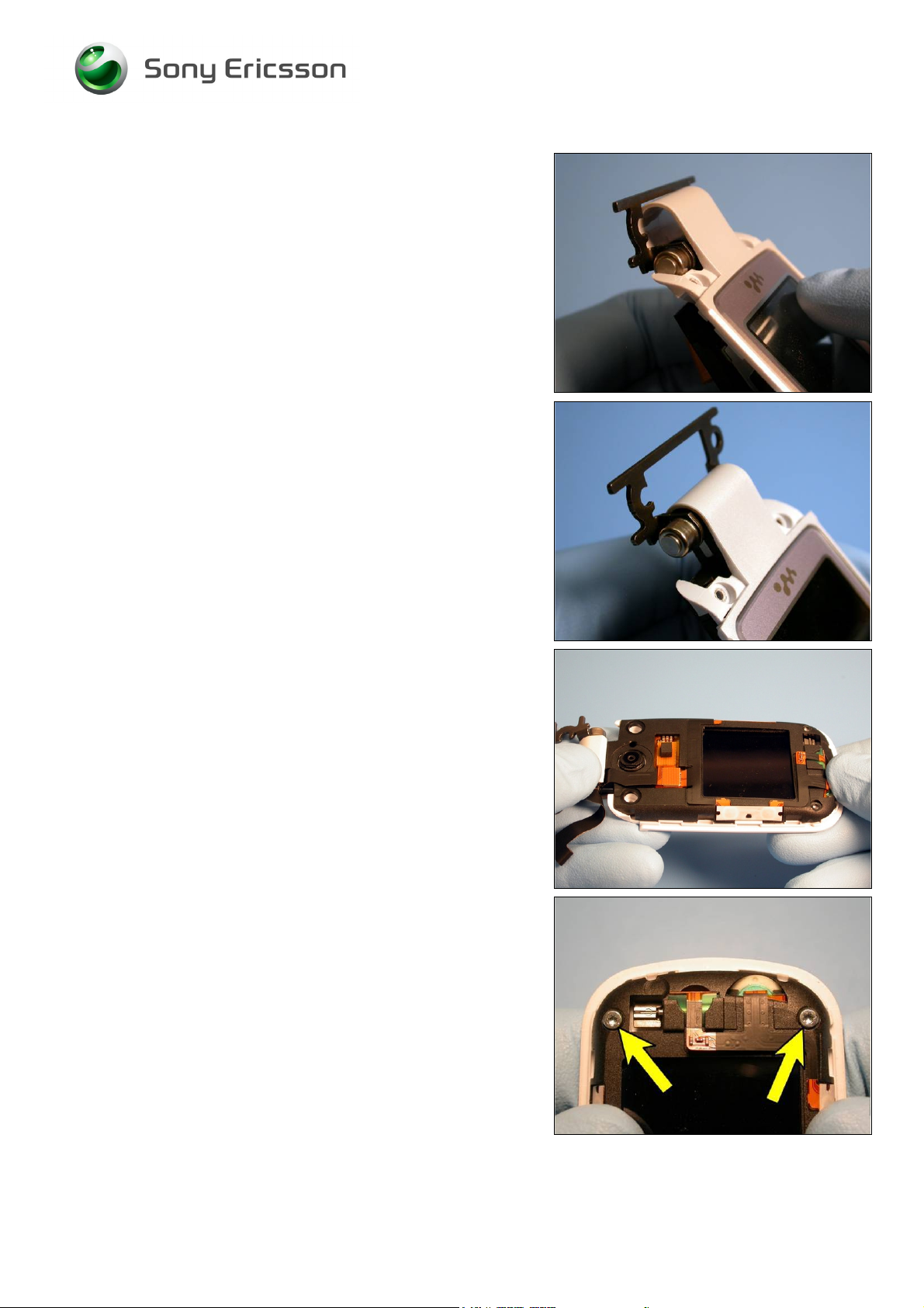
5. Using style 2A tweezers, position the screw cover so
that its tab goes into place under the hinge as
shown.
6. Seat the flip screw cover by pressing in and down
toward the main display.
7. Make sure the flip screw cover is fully seated and
that there are no gaps around it.
Starting at section 3.1.2, perform the remainder of the base
portion reassembly procedure.
4.20 Outer Flip Cover
Perform sections 2.1.1-2.2.2 of the base portion disassembly procedure.
Obtain a new Outer Flip Cover.
Starting at section 3.1.2, perform the remainder of the base portion reassembly procedure.
3/000 21-1/FEA 209 544/601 C
© Sony Ericsson Mobile Communications AB
77(101)
Page 78

Working Instruction, Mechanical
4.21 Camera Ring (Applies to W710 Only)
NOTE: THIS SECTION APPLIES TO W710 ONLY.
Perform sections 2.1.1-2.2.2 of the base portion disassembly procedure.
Obtain a new Camera Ring.
Starting at section 3.1.2, perform the remainder of the base portion reassembly procedure.
4.22 Inner Flip Cover
Perform sections 2.1.1-2.2.3 of the base portion
disassembly procedure.
1. Obtain a new inner flip cover.
2. Obtain a new inner flip cover tape and remove it
from its protective backing.
3. Position the inner flip cover tape where shown so
that the portion indicated goes over the foam. Make
sure the tape does not extend onto the display
window. Press on the tape to make sure it sticks
well.
3/000 21-1/FEA 209 544/601 C
© Sony Ericsson Mobile Communications AB
78(101)
Page 79

Working Instruction, Mechanical
4. Obtain a new receiver tape and remove it from its
protective backing.
5. Place the receiver tape as shown, making sure that
the hole in the receiver tape lines up with the hole in
the inner flip cover and that the tape extends onto
the foam around the display window. Make sure the
tape does not extend onto the display window.
6. Obtain a new receiver and position with the contact
finger side nearest to the display window. Make sure
the receiver lines up with the two alignment tabs
indicated.
7. Use the flat end of a nylon pointer to press on the
receiver so that it sticks well. Be careful to not press
directly on the contact fingers.
Starting at section 3.1.1, perform the remainder of the base
portion reassembly procedure.
3/000 21-1/FEA 209 544/601 C
© Sony Ericsson Mobile Communications AB
79(101)
Page 80

Working Instruction, Mechanical
4.23 Receiver
Perform sections 2.1.1-2.2.3 of the base portion
disassembly procedure.
1. Insert the tip of a pair of style 2A tweezers under the
receiver where shown.
2. Use the tweezers to pry the receiver free from its
location.
3. Using style 2A tweezers, remove the receiver tape.
4. Use alcohol and a lint-free wipe to remove any
remaining adhesive residue.
5. Obtain a new receiver tape and remove it from its
protective backing.
6. Place it as shown, making sure that the hole in the
receiver tape lines up with the hole in the inner flip
cover and that the tape extends onto the foam
around the display window.
3/000 21-1/FEA 209 544/601 C
© Sony Ericsson Mobile Communications AB
80(101)
Page 81

Working Instruction, Mechanical
7. Obtain a new receiver and position with the contact
finger side nearest to the display window.
8. Use the flat end of a nylon pointer to press on the
receiver so that it sticks well. Be careful to not press
directly on the contact fingers.
Starting at section 3.1.1, perform the remainder of the base
portion reassembly procedure.
3/000 21-1/FEA 209 544/601 C
© Sony Ericsson Mobile Communications AB
81(101)
Page 82

Working Instruction, Mechanical
4.24 Magnet
Perform sections 2.1.1-2.2.3 of the base portion
disassembly procedure.
1. Use style 2A tweezers to remove the old magnet.
2. Use alcohol and a lint-free cloth to remove any
adhesive residue.
3. Obtain a new magnet.
4. Remove the protective film from the magnet’s
adhesive and install it so that its long side matches
with the long side of the magnet cavity. The magnet
should completely fill the magnet cavity.
NOTE!
Starting at section 3.1.1, perform the remainder of the base
portion reassembly procedure.
AVOID CONTAMINATING THE MAGNET’S ADHESIVE.
5. Press on the magnet firmly to make sure it sticks
well.
3/000 21-1/FEA 209 544/601 C
© Sony Ericsson Mobile Communications AB
82(101)
Page 83

Working Instruction, Mechanical
4.25 Vibrator
Perform sections 2.1.1-2.2.3 of the base portion
disassembly procedure.
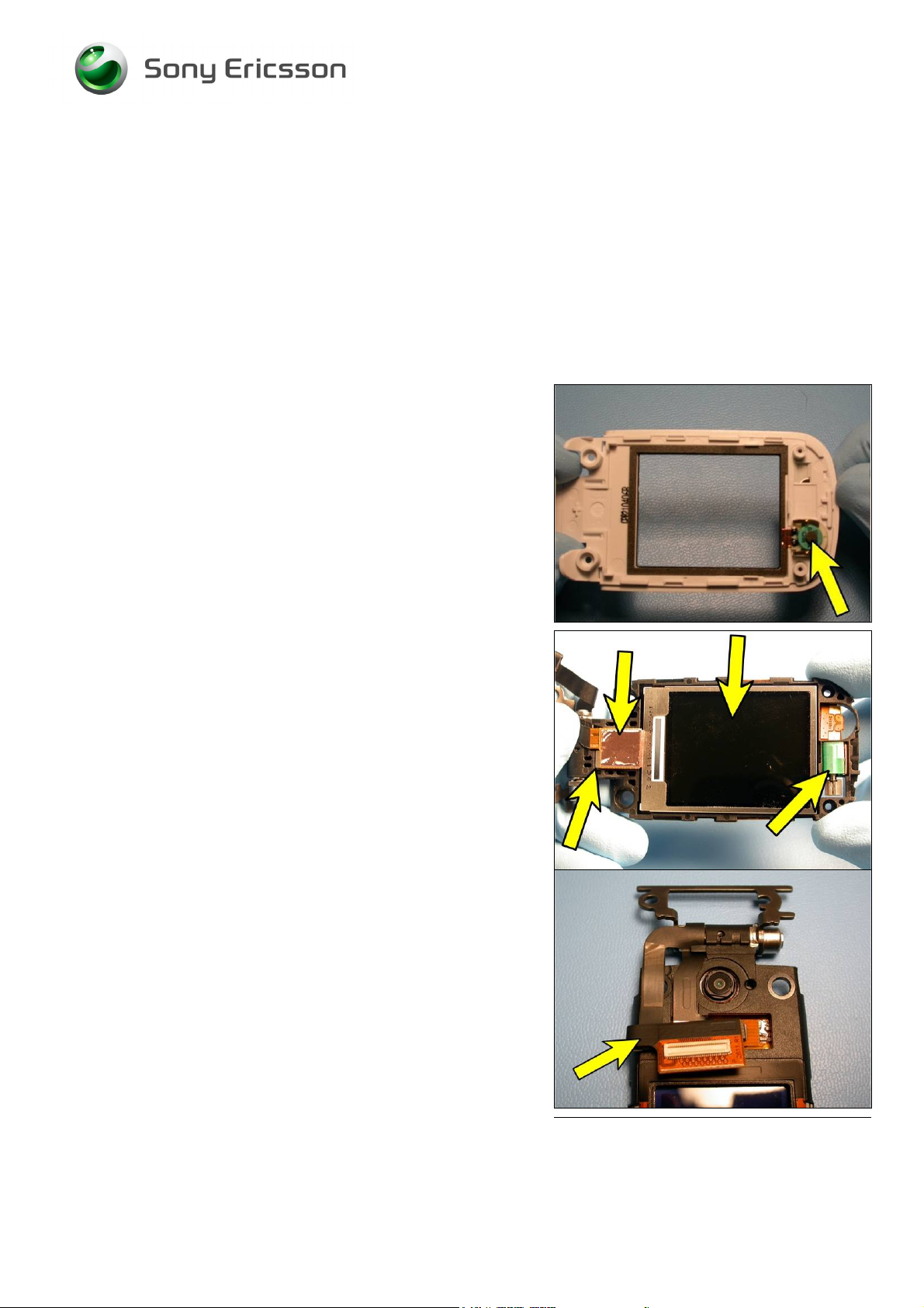
1. With the flip frame oriented as shown, locate the two
holes indicated.
2. Using style 2A tweezers, press the vibrator from its
cavity by pushing on the vibrator through the two
holes.
3. Using your finger or a nylon pointer, gently press up
on the portion of the flip flex film to which the
vibrator connects so that the flex film rises out of the
vibrator cavity.
4. Position the vibrator against the flex film so that the
vibrator’s contacts line up with the corresponding
pads on the flex film.
5. While holding the vibrator against the flex film, insert
the vibrator and its flex film down into the cavity as
shown.
Starting at section 3.1.1, perform the remainder of the base
portion reassembly procedure.
3/000 21-1/FEA 209 544/601 C
© Sony Ericsson Mobile Communications AB
83(101)
Page 84

Working Instruction, Mechanical
4.26 Display Assembly
Perform sections 2.1.1-2.2.3 of the base portion
disassembly procedure.
1. Orient the flip frame so that the small display is
toward you, and so that your hand is under the large
display.
2. Using a pry tool, disconnect the main flex assembly
from the display assembly as shown. The display
assembly will fall out of the back of the flip frame
into your hand.
3. Obtain a new display assembly and insert it into the
flip frame as shown.
4. While holding the display assembly in place,
connect the main flex assembly to the display as
shown.
Starting at section 3.1.1, perform the remainder of the base
portion reassembly procedure.
3/000 21-1/FEA 209 544/601 C
© Sony Ericsson Mobile Communications AB
84(101)
Page 85

Working Instruction, Mechanical
4.27 Main Flex Assembly
Perform sections 2.1.1-2.2.3 of the base portion
disassembly procedure.
1. Orient the flip frame so that the small display is
toward you and your hand is under the large display.
2. Using a pry tool, disconnect the main flex assembly
from the display assembly as shown.
3. Using a pry tool, disconnect the main flex assembly
from the flip flex film assembly as shown.
4. The display assembly will fall out of the flip frame
and into your hand. Set the display aside.
5. Remove the camera module from its location and
peel the flex film upward off of the flip frame.
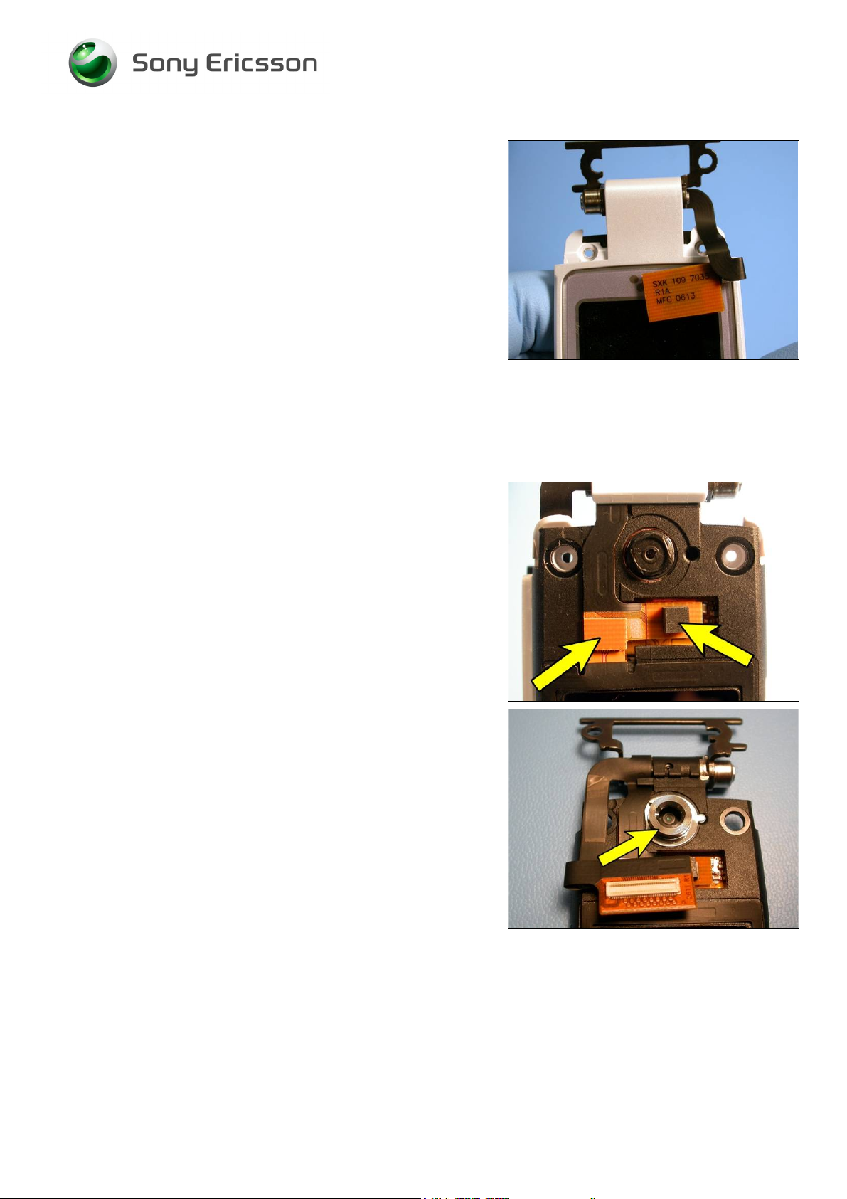
6. Slide the flex film from under its retainer tab.
3/000 21-1/FEA 209 544/601 C
© Sony Ericsson Mobile Communications AB
85(101)
Page 86

Working Instruction, Mechanical
7. Remove the main flex from the flip frame by passing
the camera module through the opening in the
hinge.
8. Obtain a new main flex assembly.
9. Obtain a new camera module and insert it into the
camera socket so that the alignment tab goes into
the alignment slot. The camera will only fit in this
orientation.
3/000 21-1/FEA 209 544/601 C
© Sony Ericsson Mobile Communications AB
86(101)
Page 87

Working Instruction, Mechanical
10. Obtain a new camera shield cover and place it over
the camera as shown. Push the shield can down
over the camera so that it snaps into place.
11. Obtain a new camera foam pad and install it on the
side of the camera opposite from the flex film.
3/000 21-1/FEA 209 544/601 C
© Sony Ericsson Mobile Communications AB
87(101)
Page 88

Working Instruction, Mechanical
12. Obtain a new camera tape and place the hole in the
tape around the camera module. Fold the tape down
and around the camera module so that it follows the
contour of the foam pad.
13. Obtain a new LCD connector pad and remove it
from its protective backing.
14. Place the pad in its location on the main flex to LCD
connector and press on it to make sure it sticks well.
15. Pass the camera module through the opening in the
metal hinge.
NOTE!
BE CAREFUL TO NOT DAMAGE THE CAMERA.
3/000 21-1/FEA 209 544/601 C
© Sony Ericsson Mobile Communications AB
88(101)
Page 89

Working Instruction, Mechanical
16. Place the camera into its cavity and hold it there.
17. Position the flex film under its retainer tab.
18. Remove the camera from its cavity and lift it to
remove the protective film from the adhesive on the
flex film.
19. Place the camera back into its cavity and smooth
the flex film down so that its adhesive sticks to the
flip frame.
3/000 21-1/FEA 209 544/601 C
© Sony Ericsson Mobile Communications AB
89(101)
Page 90

Working Instruction, Mechanical
20. Reposition the circuit board connector portion of the
main flex assembly to the main display side of the
flip frame. Be careful with the main flex film; do not
over stress it as it can tear easily.
21. Insert the display assembly into the flip frame.
22. Hold the display assembly in place and connect the
main flex assembly to the display and flip flex
assembly as shown.
Starting at section 3.1.1, perform the remainder of the base
portion reassembly procedure.
3/000 21-1/FEA 209 544/601 C
© Sony Ericsson Mobile Communications AB
90(101)
Page 91

Working Instruction, Mechanical
4.28 Flip Flex Assembly
Perform sections 2.1.1-2.2.3 of the base portion
disassembly procedure.
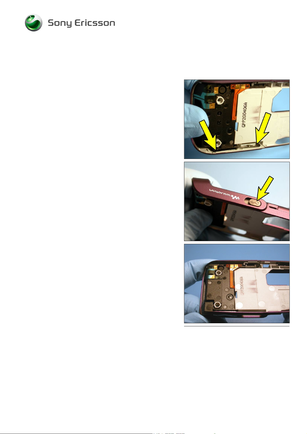
1. With the flip frame oriented as shown, locate the two
holes indicated.
2. Using style 2A tweezers, press the vibrator from its
cavity by pushing on the vibrator through the two
holes.
NOTE!
AVOID DAMAGING THE VIBRATOR’S CONTACTS.
3. Orient the flip frame so that the small display is
toward you and your hand is under the large display.
4. Using a pry tool, disconnect the main flex assembly
from the display assembly as shown.
5. Using a pry tool, disconnect the main flex assembly
from the flip flex film assembly as shown.
6. The display assembly will fall out of the flip frame
and into your hand. Set the display aside.
3/000 21-1/FEA 209 544/601 C
© Sony Ericsson Mobile Communications AB
91(101)
Page 92

Working Instruction, Mechanical
7. The flip flex assembly is adhered to the flip frame
where indicated. Use style 2A tweezers to pull it off
of the flip frame.
8. The receiver contact portion of the flip flex assembly
is adhered to the flip frame. Use style 2A tweezers
to pull it off of the flip frame.
9. Pull the vibrator and receiver contact portions of the
flip flex assembly through their holes in the flip
frame.
10. Obtain a new flip flex assembly.
3/000 21-1/FEA 209 544/601 C
© Sony Ericsson Mobile Communications AB
92(101)
Page 93

Working Instruction, Mechanical
11. Insert the receiver contact portion and the vibrator
contact portion of the flip flex assembly through their
openings in the flip frame as shown.
12. Remove the protective film from the back of the
receiver contact portion of the flip flex film.
13. Using a pry tool, press the receiver contact portion
of the flip flex film into place so that it adheres to the
flip frame as shown.
14. Fold the flip flex assembly onto the flip frame so that
it is positioned as shown.
15. Remove the protective film from the back side of
each of the side key portions of the flip flex and
position them in their flip frame cavities so that they
fit over the alignment pegs in the cavities.
16. Apply pressure to the side key portions of the flip
flex so that a good bond to the flip frame occurs.
3/000 21-1/FEA 209 544/601 C
© Sony Ericsson Mobile Communications AB
93(101)
Page 94

Working Instruction, Mechanical
17. Insert the display into the flip frame and hold it in
place.
18. Connect the main flex assembly to the display
assembly and flip flex assembly as shown.
19. Using your finger or a nylon pointer, gently press up
on the portion of the flip flex film to which the
vibrator connects so that the flex film rises out of the
vibrator cavity.
6. Position the vibrator against the flex film as shown
so that the vibrator’s contacts line up with the
corresponding pads on the flex film.
7. While holding the vibrator against the flex film, insert
the vibrator and its flex film down into the cavity as
shown.
Starting at section 3.1.1, perform the remainder of the base
portion reassembly procedure.
3/000 21-1/FEA 209 544/601 C
© Sony Ericsson Mobile Communications AB
94(101)
Page 95

Working Instruction, Mechanical
4.29 Camera Module
1. To replace the camera module, perform the main
flex film assembly replacement procedure.
4.30 Flip Frame
Perform sections 2.1.1-2.2.3 of the base portion
disassembly procedure.
1. Orient the flip frame so that the small display is
toward you and your hand is under the large display.
2. Using a pry tool, disconnect the main flex assembly
from the display assembly as shown.
3. Using a pry tool, disconnect the main flex assembly
from the flip flex film assembly as shown.
4. The display assembly will fall out of the flip frame
and into your hand. Set the display aside.
3/000 21-1/FEA 209 544/601 C
© Sony Ericsson Mobile Communications AB
95(101)
Page 96

Working Instruction, Mechanical
5. Remove the camera module from its cavity and peel
the flex film upward off of the flip frame.
6. Slide the flex film from under its retainer tab.
7. Remove the main flex from the flip frame by passing
the camera module through the opening in the
hinge.
8. With the flip frame oriented as shown, locate the two
holes indicated.
9. Using style 2A tweezers, press the vibrator from its
cavity by pushing on the vibrator through the two
holes. Set the vibrator aside.
NOTE!
BE CAREFUL TO NOT DAMAGE THE VIBRATOR
CONTACTS
.
3/000 21-1/FEA 209 544/601 C
© Sony Ericsson Mobile Communications AB
96(101)
Page 97

Working Instruction, Mechanical
10. Use style 2A tweezers to remove the magnet.
11. Obtain a new flip frame.
12. Install the magnet so that its long side matches with
the long side of the magnet cavity. The magnet
should completely fill the magnet cavity.
NOTE!
AVOID CONTAMINATING THE MAGNET’S ADHESIVE.
13. Obtain a new flip flex film and position the receiver
contact portion and the vibrator contact portion of
the flip flex assembly through their openings in the
flip frame as shown.
3/000 21-1/FEA 209 544/601 C
© Sony Ericsson Mobile Communications AB
97(101)
Page 98

Working Instruction, Mechanical
14. Use a pry tool to press the receiver contact portion
down so that it sticks to the flip frame as shown.
15. Fold the flip flex assembly onto the flip frame so that
it is positioned as shown.
16. Remove the protective film from the back side of
each of the side key portions of the flip flex and
position them in their flip frame cavities so that they
fit over the alignment pegs in the cavities.
17. Apply pressure to the side key portions of the flip
flex so that a good bond to the flip frame occurs.
18. Using your finger or a nylon pointer, gently press up
on the portion of the flip flex film to which the
vibrator connects so that the flex film rises out of the
vibrator cavity.
3/000 21-1/FEA 209 544/601 C
© Sony Ericsson Mobile Communications AB
98(101)
Page 99

Working Instruction, Mechanical
19. Position the vibrator against the flex film so that the
vibrator’s contacts line up with the corresponding
pads on the flex film.
20. While holding the vibrator against the flex film, insert
the vibrator and its flex film down into the cavity as
shown.
21. Pass the camera module through the opening in the
metal hinge.
NOTE!
BE CAREFUL TO NOT DAMAGE THE CAMERA.
3/000 21-1/FEA 209 544/601 C
© Sony Ericsson Mobile Communications AB
99(101)
Page 100

Working Instruction, Mechanical
22. Place the camera into its cavity to check that it fits.
23. Position the flex film under its retainer tab.
24. If a new main flex film is being used, remove the
camera from its cavity and lift it to remove the
protective film from the adhesive.
25. Place the camera back into its cavity and smooth
the flex film down so that its adhesive sticks to the
flip frame.
3/000 21-1/FEA 209 544/601 C
© Sony Ericsson Mobile Communications AB
100(101)
 Loading...