

Page 1
Component Replacement
- electrical -
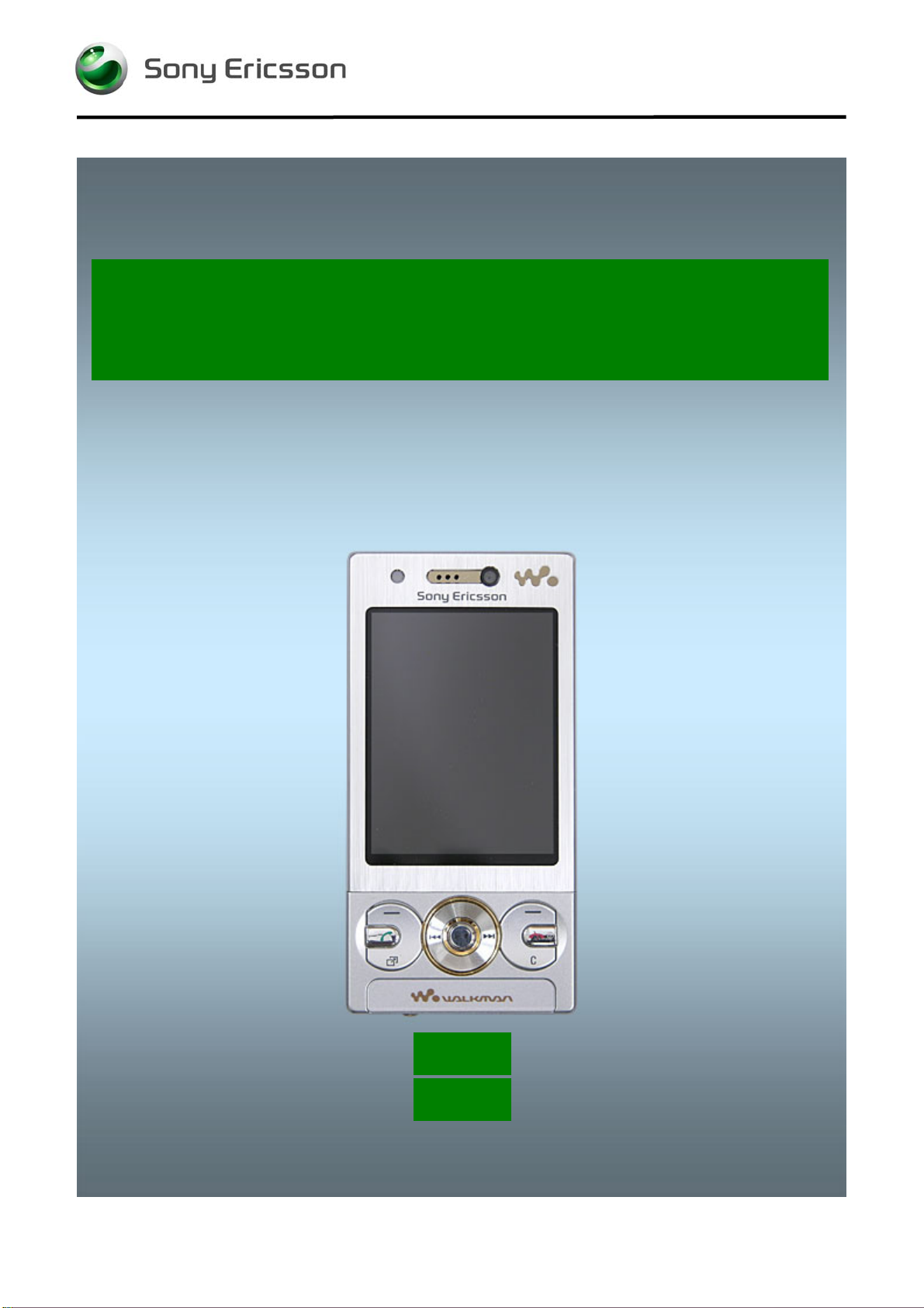
W705
W715
1225-1006 Rev 1
© Sony Ericsson Mobile Communications AB – Company Internal
Page 2
Component Replacement (elect)
CONTENTS
1 Replaceable Components ............................................................... 3
2 Component Placing .......................................................................... 5
3 Repair Actions .................................................................................. 6
3.1 Shield Can Fence Modifications ............................................................. 6
3.2 Additional Repair Info ............................................................................. 7
4 Revision History ............................................................................. 11
For general information about electrical repair related issues, refer to
1220-1336: Generic Repair Manual - electrical
1225-1006 Rev 1
© Sony Ericsson Mobile Communications AB – Company Internal
2(11)
Page 3
Component Replacement (elect)
1 Replaceable Component s
EXPLANATION OF ABBREVIATIONS USED IN THE COLUMN ‘COMMENTS’ BELOW
COMPONENT LOCATION
P = Primary side
S = Secondary side
REPAIR METHOD
HA = Hot Air (removal & mounting)
HA/ST = Hot Air for removal - Soldering Tool for mounting
BGA = BGA Station
BH= Bottom heat
ADDITIONAL INFORMATION
Ö1 (2,3,4, etc.) = Proceed to ‘Additional Repair Info’ for further instructions in the indicated section(s).
CALIBRATION
C = Calibration of the phone is required after replacing the component
Calibration to be done by authorized centers only!
Position Designation Part no. Comments
B1400
B2000
B2100
B3100
B4410
Osc TCXO 27,456 MHz Only Applicable for
W715
SMD Vibrator
Crystal 32768Hz
Microphone
MR Sensor
1200-7847
1202-9271
RTM501911/2R1A
1210-7410
RYN901920/1
C2214 Capacitor Electrolytic 70.0 mF None 3.3 V 1203-3900 P HA
L2200
L2201
L2401
L2402
L2403
L2404
L2405
L2406
L2408
L4200
N1200
N1200
N1210
N1211
N1300
N1400
N1410
N1510
N2200
N2201
N2203
N2204
N2300
Ind WW 4.7 uH K3012
120ohm 0603 2A 50mohm Bead
Inductor
Inductor
Inductor
Inductor
Inductor
Ind Chip 0, H
Inductor
22uH 20% 3x3x1.2mm 0.375A 0.63ohm
Pre-bumped Tiger Band 1,8
Tiger 1,2,5 Only Applicable for W705
IC Linear
IC Voltage Regulator
Bluetooth and RDS FM radio tuner.
A-GPS Only Applicable for W715
IC Amp P-TSLP-1-1 Only Applicable for W715
Mod Radio WLAN R041D
IC Vreg MAX8640, 1.8V
IC Vreg PLP1010-4
IC Voltage Regulator
LDO1.8 V, 200mA, low noice, CS-5
ASIC Power Management
1200-2214
REG70605/15
REG70618/20
REG70618/20
REG70618/20
REG70618/20
REG70618/20
1200-6898
REG70618/20
REG7245512/22M
1218-1880
1218-1883
1203-5870
1204-5903
1200-9840
1200-0700
1200-2407
1200-6173
1200-6420
1201-6465
RYT113997/4
RYT1137816/4
1203-2790
P HA
S HA/ST Ö1
P HA C
P BGA
P HA Ö2
P HA
P HA Ö3
S HA Ö4
S HA Ö4
S HA Ö4
S HA Ö4
S HA Ö5
S HA Ö4
S HA Ö5
P HA
P BGA C
P BGA C
P HA
P HA
S BGA
P HA
P HA
S HA
P HA
P HA Ö6
S HA Ö7
S HA Ö7
P HA
1225-1006 Rev 1
© Sony Ericsson Mobile Communications AB – Company Internal
3(11)
Page 4
Component Replacement (elect)
Position Designation Part no. Comments
N2401
N2411
N2420
N2421
N2422
N3100
N3101
R2449
R2451
R2490
S2403
S2404
S2405
S2406
V2200
V2202
V2415
V2416
V2417
V2470
V3101
V4203
X1000
X1001
X1002
X1003
X1004
X1005
X1200
X1500
X2201
X2401
X2402
X2403
X2405
X3102
X4200
X4300
Z2400
Z4200
Z4201
Z4202
Transistor
ASIC Accelerometer
IC IF ISP1508 ES3 (3.5*3.5*0.8)
IC ESD Prot UDFN 6 2x2 mm
ASIC Baseband
IC CS-9
Asic
Resistor 0, Ohm +/-50m 63 mW K0603
Resistor 0.0 Ohm +/-5% NA mW K0402
Resistor 0, Ohm +/-50m 63 mW K0603
Input Switch
Input Switch Side Push
Input Switch
Input Switch
Diode
Transistor
Diode
Diode
TVS Diode 12V 38pF
Switching Diode
Zenner Diode, ESD protection, 6.1V
Trans NPN
Conn Leaf Spring
ANT GND Connector Leaf Spring 1p
Conn Leaf Spring
Conn Leaf Spring
ANT GND Connector Leaf Spring 1p
Conn Leaf Spring
Connector
Connector
Conn Pogopin 5p
Conn BtB Receptacle 16p
Conn BtB
Memory Card Conn
System connector I/O Receptacle 12p
Conn WtB Receptacle 2p
Conn BtB Receptacle 70p
Conn Camera Socket 0p
Filter
Filter 400.0 MHz KNA16400
Filter 400.0 MHz KNA16400
Filter 400.0 MHz KNA16400
RYN901936/1
1202-1676
1200-1694
1200-6309
1201-4120
1200-9978
ROP1013074/1R1A
REP623001/0
REP622001/0
REP623001/0
RMD10116/9R1A
1206-9606
RMD10116/9R1A
RMD10116/9R1A
RKZ223911/1
RYN122910/1
1201-8440
1201-8440
1200-5130
RKZ323916/1
RKZ223922/1
1211-3641
1201-4841
1202-1053
1201-4841
1201-4841
1202-1053
1201-4841
1203-9688
1203-9688
1206-2937
1214-7370
1200-9864
RNK87147/2
1205-9723
1206-4855
1206-2940
1206-5418
1201-6833
REV50146/1
REV50146/1
REV50146/1
P HA
P HA Ö8
P HA
P HA Ö3
P HA
P HA
P HA Ö3
S HA Ö4
S HA Ö4
S HA Ö4
P HA/ST
S HA/ST
P HA/ST
P HA/ST
S HA Ö9
P HA
P HA Ö3
P HA Ö3
S HA Ö5
P HA Ö10
P HA Ö11
P HA
P HA/ST
P HA/ST Ö12
P HA/ST Ö13
P HA/ST
P HA/ST Ö14
P HA/ST Ö2
P HA/ST Ö15
P HA/ST Ö3
S BH/HA
P HA
S HA Ö16
P BGA
S HA/ST
S HA
P BGA
S HA/SI
P HA Ö3
P HA Ö8
P HA Ö8
P HA Ö8
1225-1006 Rev 1
© Sony Ericsson Mobile Communications AB – Company Internal
4(11)
Page 5

Component Replacement (elect)
2 Component Placing
To access the Component Placing document for W705, double-click the icons below.
To access the Component Placing document for W715, double-click the icons below.
1225-1006 Rev 1
© Sony Ericsson Mobile Communications AB – Company Internal
5(11)
Page 6
Component Replacement (elect)
3 Rep air Actions
Refer to the Tools Catalogue and/or Tools Matrix for information about equipment that is required
for PBA repair!
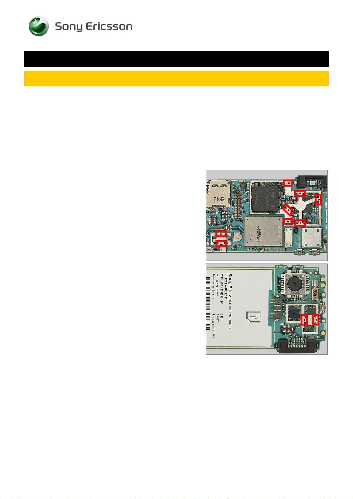
3.1 Shield Can Fence Modifications
Refer to the pictures below of the primary and secondary sides for repairs that require the Shield Can
Fence to be modified:
• the shield can lid has to be removed
• the red symbols show where the frame should be cut to enable rework
• after rework the height of the frame should not be affected
• it should not be visible that rework has been carried out when the lid has been mounted
Side A
Side B
1225-1006 Rev 1
© Sony Ericsson Mobile Communications AB – Company Internal
6(11)
Page 7
Repair Actions
3.2 Additional Repair Info
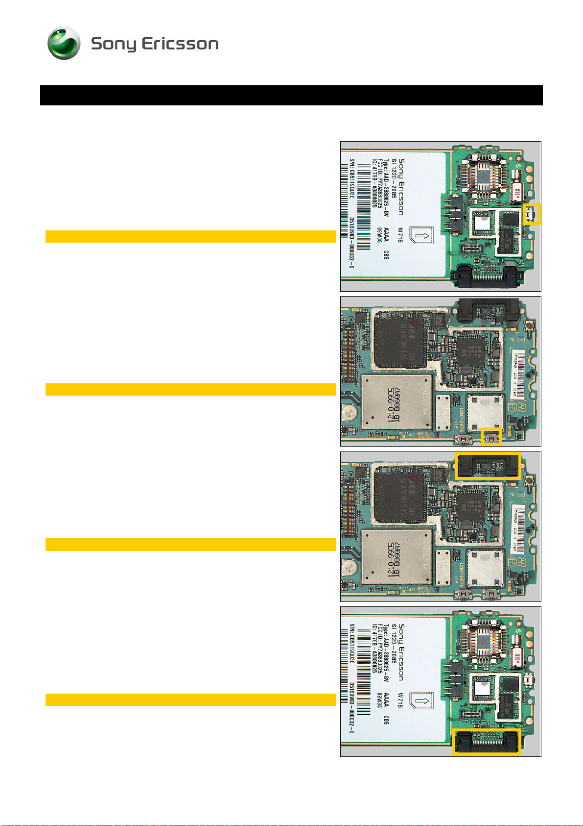
1
B2000
Protect the switch with capton tape!
Component Replacement (elect)
2
B4410, X1005
Protect the switch with capton tape!
3
L2201, N2421, N3101, V2415, V2416, X1500, Z2400
Protect the system connector with capton tape!
4
L2401-2404, L2406, R2449, R2451, R2490
Protect the system connector with capton tape!
1225-1006 Rev 1
© Sony Ericsson Mobile Communications AB – Company Internal
7(11)
Page 8
Repair Actions: Additional Repair Info
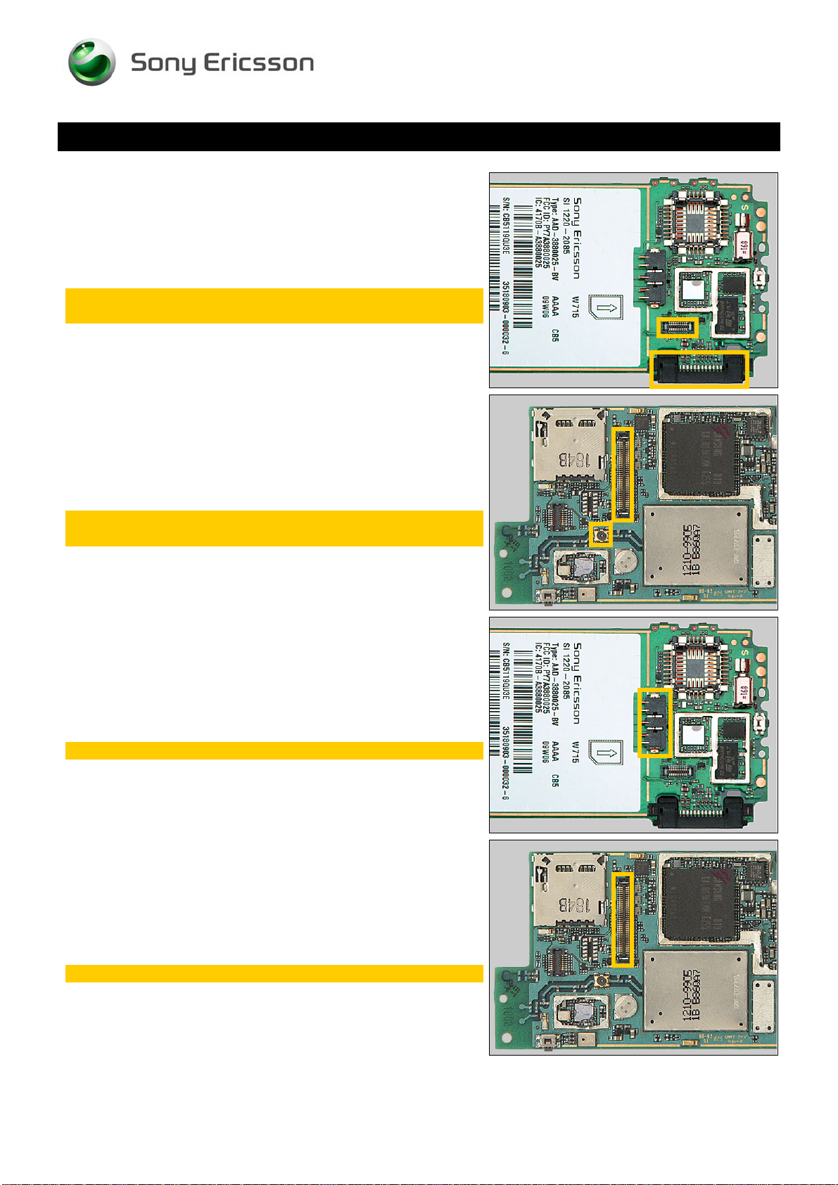
5
L2405, L2408, V2417
Protect the BtB connector and system connector with
capton tape!
Component Replacement (elect)
6
N2201
Protect the coax connector and BtB connector with
capton tape!
7
N2203, N2204
Protect the battery connector tape!
8
N2411, Z4200-Z4202
Protect the BtB connector with capton tape!
1225-1006 Rev 1
© Sony Ericsson Mobile Communications AB – Company Internal
8(11)
Page 9

Repair Actions: Additional Repair Info
9
V2200
Protect the battery connector with capton tape!
Component Replacement (elect)
10
V2470
Protect the BtB connector and coax connector with
capton tape!
11
V3101
Protect the memory card holder and BtB connector with
capton tape!
12
X1001
Protect the memory card holder with capton tape!
1225-1006 Rev 1
© Sony Ericsson Mobile Communications AB – Company Internal
9(11)
Page 10
Repair Actions: Additional Repair Info
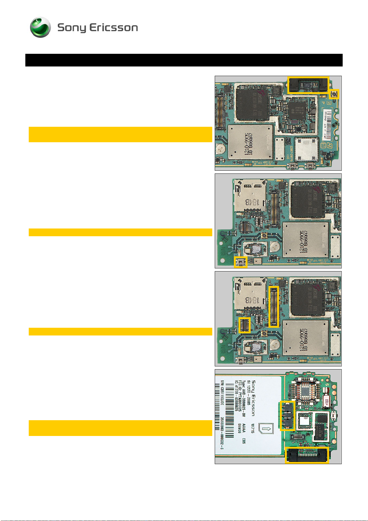
13
X1002
Protect the system connector and the coax connector
with capton tape!
Component Replacement (elect)
14
X1004
Protect the switch with capton tape!
15
X1200
Protect the two BtB connectors with capton tape!
16
X2402
Protect the battery connector and system connector
with capton tape!
1225-1006 Rev 1
© Sony Ericsson Mobile Communications AB – Company Internal
10(11)
Page 11

4 Revision History
Rev. Date Changes / Comments
1 2009-Feb-25 Initial release
Component Replacement (elect)
1225-1006 Rev 1
© Sony Ericsson Mobile Communications AB – Company Internal
11(11)
 Loading...