

Page 1

Working Instruction, SP/Mech
Working Instruction, SP/Mech
Applicable for T226, T230, T238
Contents
1
Disassembly .....................................................................................................................2
2 Reassembly ......................................................................................................................5
3 Replacement of Mechanical Parts .................................................................................8
3.1 Front Cover........................................................................................................8
3.2 Inlay................................................................................................................. 15
3.3 Microphone Grommet .....................................................................................19
3.4 Microphone .....................................................................................................20
3.5 LCD Assembly ................................................................................................ 21
3.6 Keypad.............................................................................................................24
3.7 Antenna/Antenna Cover Replacement ............................................................26
3.8 SEMC Icon ...................................................................................................... 31
3.9 Keypad PCB Assembly ...................................................................................33
3.10 Receiver and Receiver Gasket......................................................................... 34
3.11 Polyphonic Speaker and Speaker Grommet ....................................................36
3.12 Volume Switch and/or Volume Button ...........................................................38
3.13 Vibrator ...........................................................................................................41
3.14 Label Replacement ..........................................................................................42
3.15 Frame Replacement ......................................................................................... 43
4 Revision History............................................................................................................ 49
3/000 21-1/FEA 209 544/574 C
Sony Ericsson Mobile Communications AB
Page 2
Working Instruction, SP/Mech
1 Disassembly
• Tools: torque screwdriver, T6 Torx® bit, ESD-safe tweezers, orange stick, nylon pointer, front
opening tool
NOTE! Whenever the phrase “pry tool” is used, a nylon pointer, an orange stick, or a
front opening tool may be used, depending on the user’s preference.
Step-by-Step Instructions
NOTE! Keep all contact surfaces clean of dirt
and hand grease! Use finger cots or
gloves, and an ESD wrist strap!
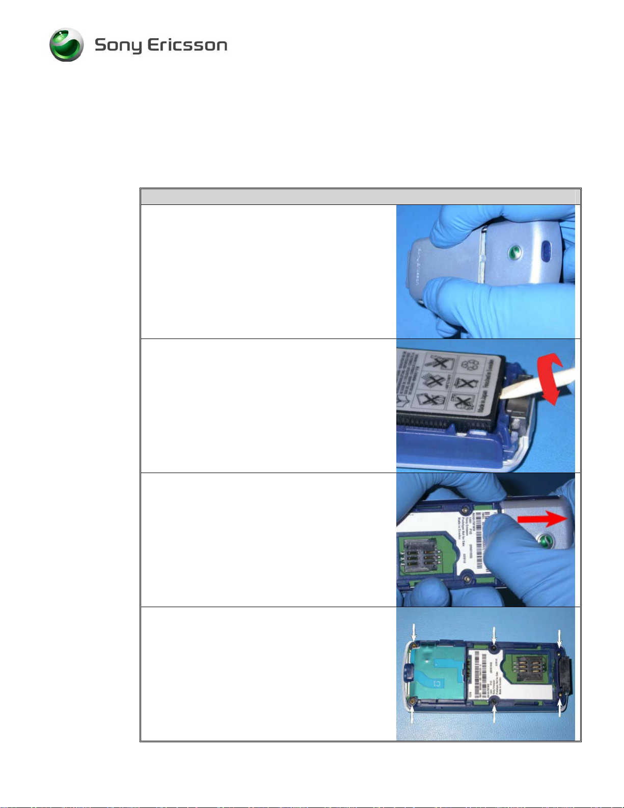
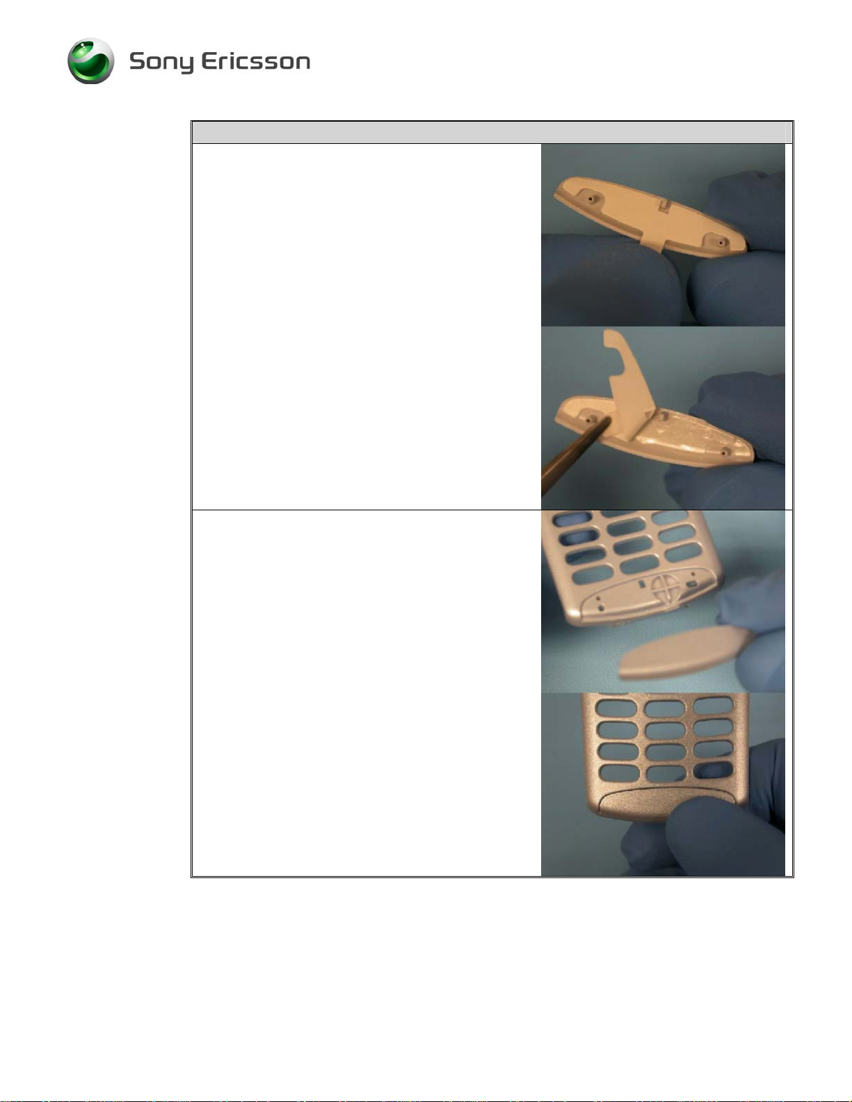
1. Remove the battery cover by sliding it down
towards the bottom of the phone and lifting it
off.
2. Remove the battery by inserting a pry tool
underneath the tab at the bottom of the battery
and rotating the pry tool so that the flat edge of
the tool moves into a vertical orientation.
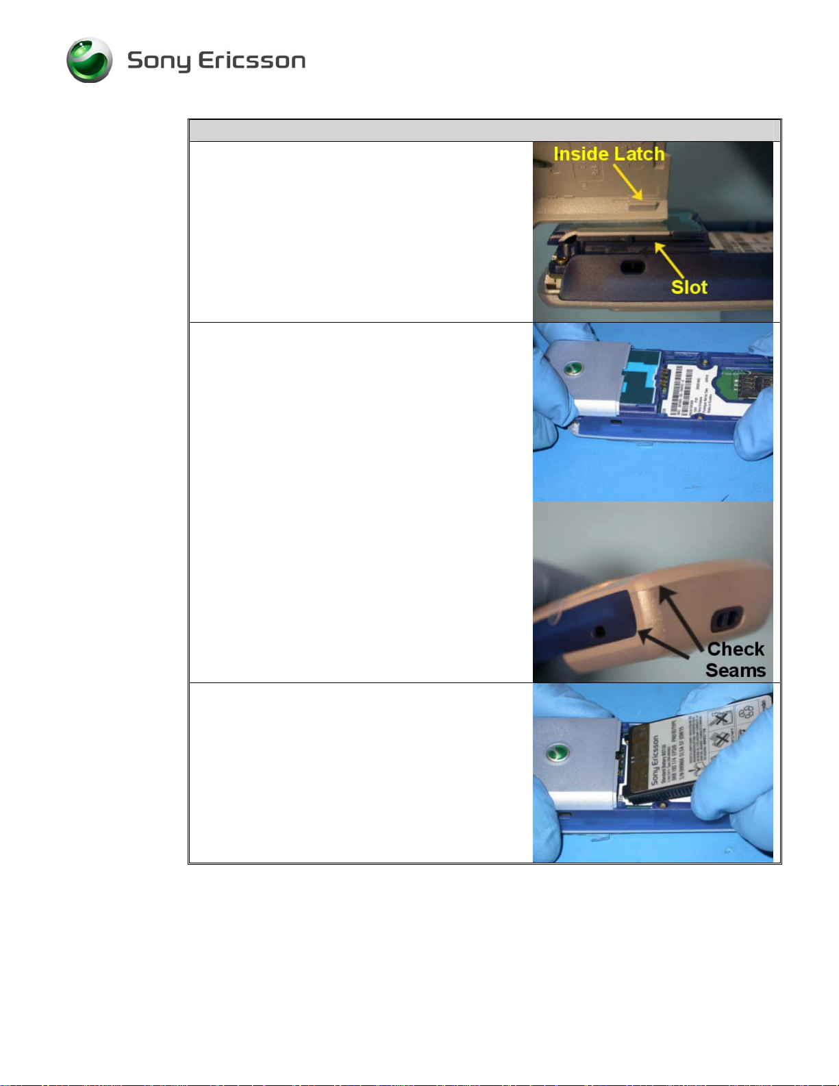
3. While lifting up the edge of the antenna cover
adjacent to the battery cavity, slide the cover
towards the top of the phone.
4. Once the antenna cover reaches the point where
it will no longer slide forward, lift the antenna
cover off of the phone.
5. Remove the six screws indicated.
3/000 21-1/FEA 209 544/574 C
Sony Ericsson Mobile Communications AB
2(49)
Page 3
Working Instruction, SP/Mech
Step-by-Step Instructions
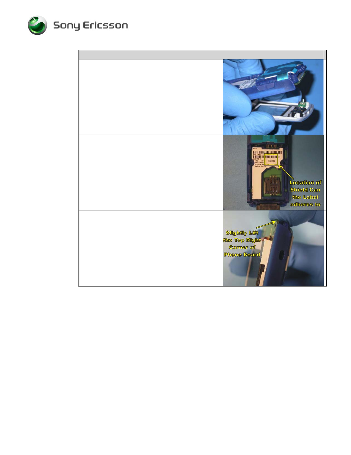
6. Remove the front cover assembly from the back
frame.
NOTE! The label tends to adhere to the top of
the shield can on the phone board that is
below the battery connector. Be careful
not to damage the label when removing
the phone board in the event that the
needed repair does not require label
replacement.
7. To remove the phone board and avoid damaging
the label, slightly lift the top corner of the phone
board that is near the speaker port.
3/000 21-1/FEA 209 544/574 C
Sony Ericsson Mobile Communications AB
3(49)
Page 4
Working Instruction, SP/Mech
Step-by-Step Instructions
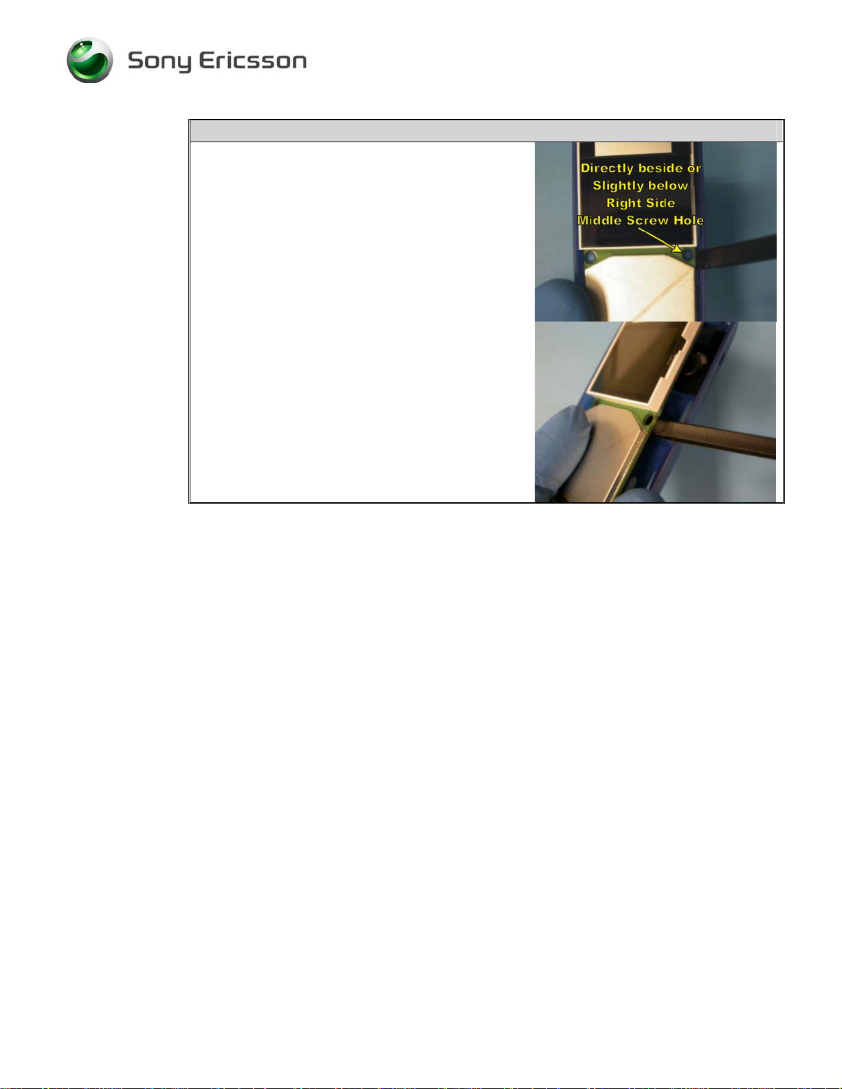
8. With the right side of the phone board slightly
lifted from the back frame, insert a pry tool
between the side of the back frame and the edge
of the board directly beside or slightly below the
middle screw holes in the board. Then gently
pry the phone board from the back frame.
3/000 21-1/FEA 209 544/574 C
Sony Ericsson Mobile Communications AB
4(49)
Page 5
Working Instruction, SP/Mech
2 Reassembly
• Tools: torque screwdriver, T6 Torx® bit, ESD-safe tweezers
Step-by-Step Instructions
NOTE! Keep all contact surfaces clean of dirt and
hand grease! Use finger cots or gloves, and an
ESD wrist strap!
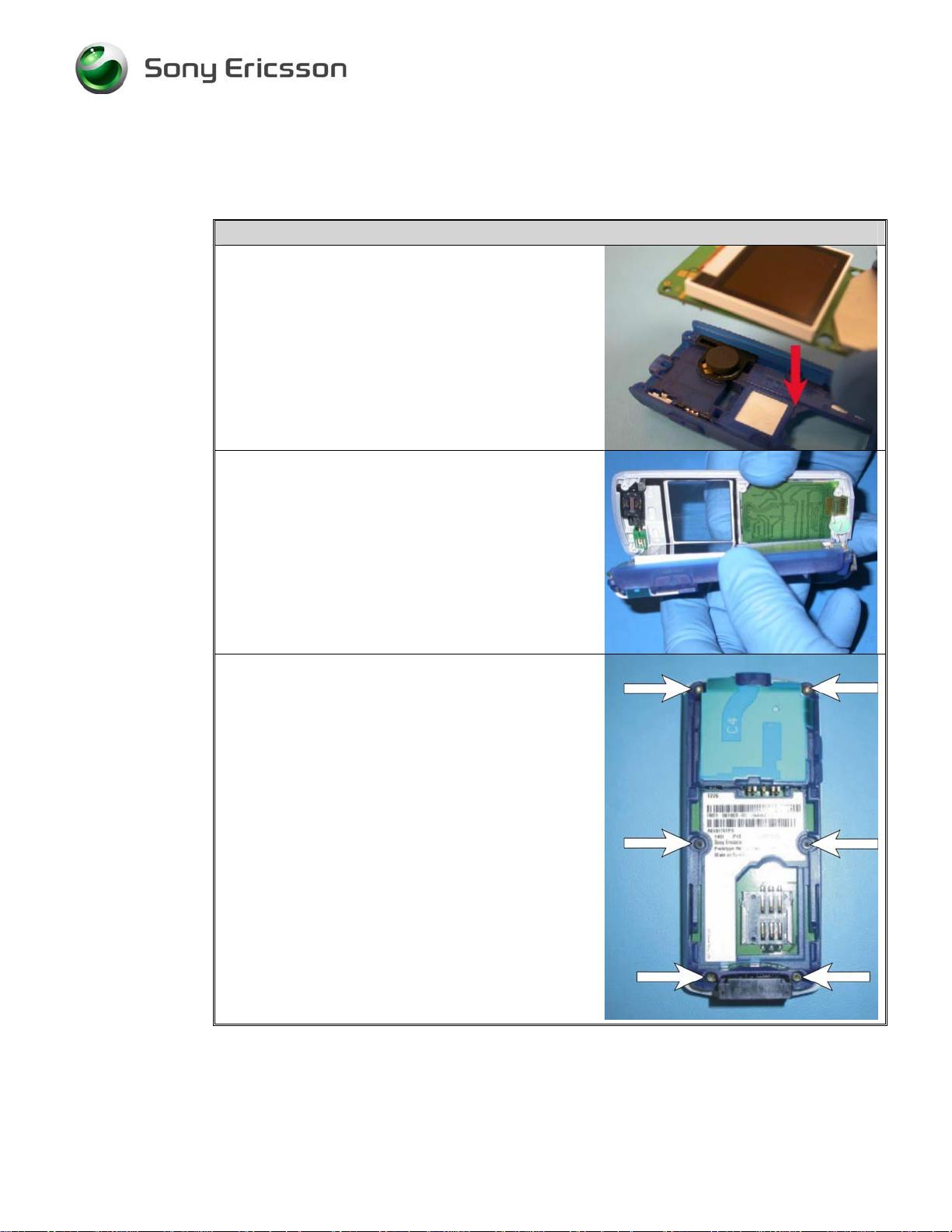
1. Place the phone board into the back frame.
2. Place the front cover and the back frame
assembly together.
NOTE! Before replacing the front cover, make sure
that there is no dust, debris, or fingerprints on
the LCD or the inside of the front cover
window!
3. Using a T6 Torx® bit in a torque driver set at 17
N-cm, reinstall the six screws in the following
order:
1 - Top Left
2 - Bottom Right
3 - Bottom Left
4 - Top Right
5 - Middle Left
6 - Middle Right
NOTE! The short black screws are used in the
middle holes. The longer gold screws are used
in the top and bottom holes.
3/000 21-1/FEA 209 544/574 C
Sony Ericsson Mobile Communications AB
5(49)
Page 6
Working Instruction, SP/Mech
Step-by-Step Instructions
4. Place the antenna cover over the antenna so the
latches on the inside surface of the antenna cover
line up with the corresponding slots in the back
frame.
5. Push the antenna cover toward the bottom of the
phone until it clicks into place.
NOTE! Check that the seam where the antenna
cover and the front cover come together is flush
and even. Also check that the seams where the
antenna cover and the back frame come together
are flush and even.
6. Starting with the top of the battery, place the
battery, label-side up, into the battery cavity.
Make sure that the tabs at the top of the battery
fit into the corresponding slots in the top of the
battery cavity.
3/000 21-1/FEA 209 544/574 C
Sony Ericsson Mobile Communications AB
6(49)
Page 7
Working Instruction, SP/Mech
Step-by-Step Instructions
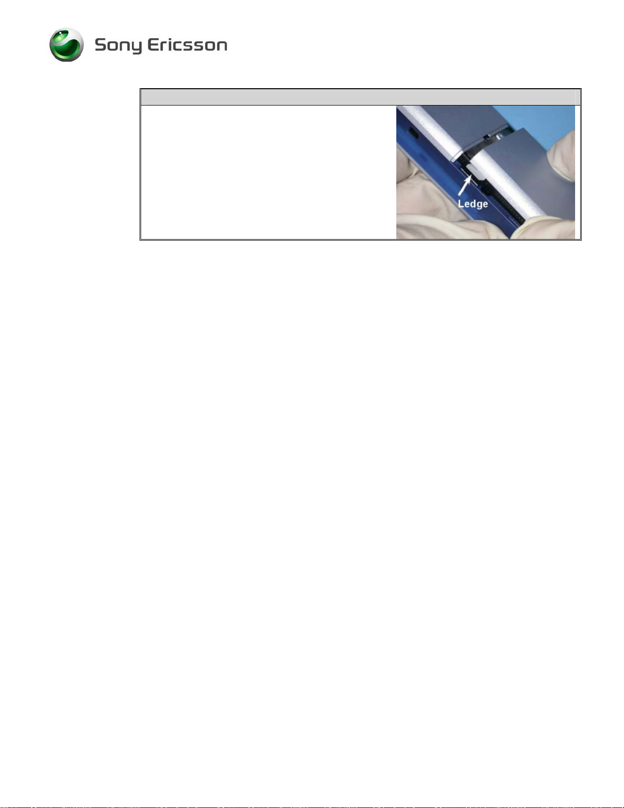
7. Place the battery cover over the battery, so that
the ledge on each side of the battery cover fits
into the corresponding slots in the back frame on
each side of the battery cavity.
8. Slide the battery cover upward until it is securely
closed.
3/000 21-1/FEA 209 544/574 C
Sony Ericsson Mobile Communications AB
7(49)
Page 8
Working Instruction, SP/Mech
3 Replacement of Mechanical Parts
3.1 Front Cover
• Tools: ESD-safe tweezers, orange stick, nylon pointer, front opening tool
NOTE! Whenever the phrase “pry tool” is used, a nylon pointer, an orange stick, or a
front opening tool may be used, depending on the user’s preference.
• Disassembly steps 1 - 5
Step-by-Step Instructions
NOTE! Keep all contact surfaces clean of dirt
and hand grease! Use finger cots or
gloves, and an ESD wrist strap!
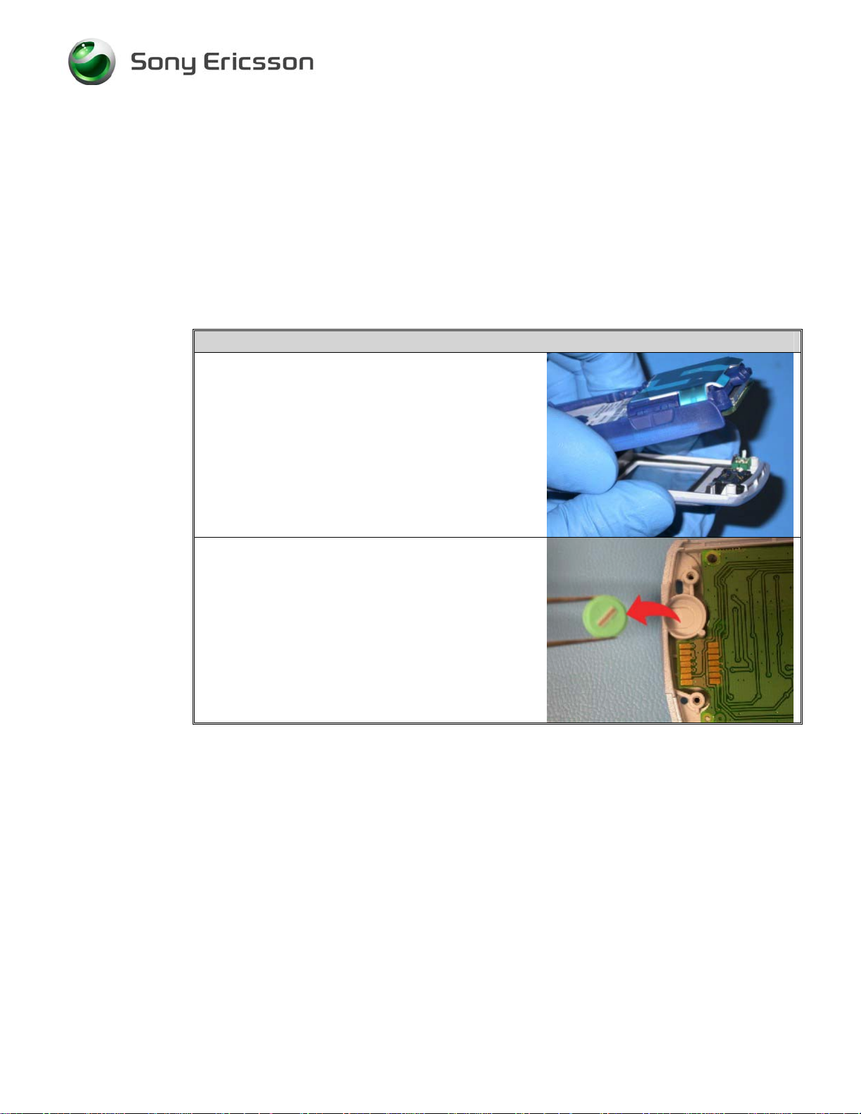
1. Remove the old front cover assembly from the
phone.
2. Remove the microphone grommet and
microphone from the microphone cavity at the
bottom of the front cover. Set the microphone
aside for safekeeping and dispose of the
microphone grommet since it cannot be reused
once the phone has been opened (screws
removed).
3/000 21-1/FEA 209 544/574 C
Sony Ericsson Mobile Communications AB
8(49)
Page 9
Working Instruction, SP/Mech
Step-by-Step Instructions
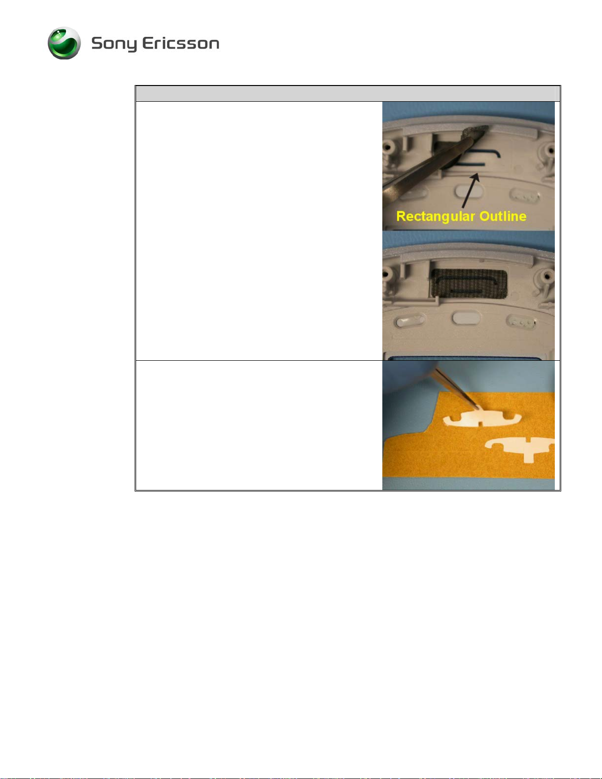
3. In a new front cover, install a speaker cloth over
the speaker ports. Make sure the speaker cloth
completely covers the speaker ports.
NOTE! The speaker cloth should lie within the
rectangular outline that is around the
speaker ports.
4. Once the speaker cloth is positioned, press
around the outer edge of the speaker cloth to
assure good adhesion to the front cover.
5. Remove an inlay adhesive film/backing
assembly from the large strip of backing
containing the adhesive film/backing assemblies.
3/000 21-1/FEA 209 544/574 C
Sony Ericsson Mobile Communications AB
9(49)
Page 10
Working Instruction, SP/Mech
Step-by-Step Instructions
6. Place the adhesive film/backing assembly on an
inlay and remove the backing from the adhesive
film.
NOTE! The three notches in the adhesive film
should line up with the three pegs on the
inlay.
7. Alien the three pegs on the inlay up with the
corresponding holes near the bottom edge of the
new front cover.
8. Apply pressure over the entire outer surface of
the inlay so that a good bond forms between the
inlay and the front cover.
3/000 21-1/FEA 209 544/574 C
Sony Ericsson Mobile Communications AB
10(49)
Page 11
Working Instruction, SP/Mech
Step-by-Step Instructions
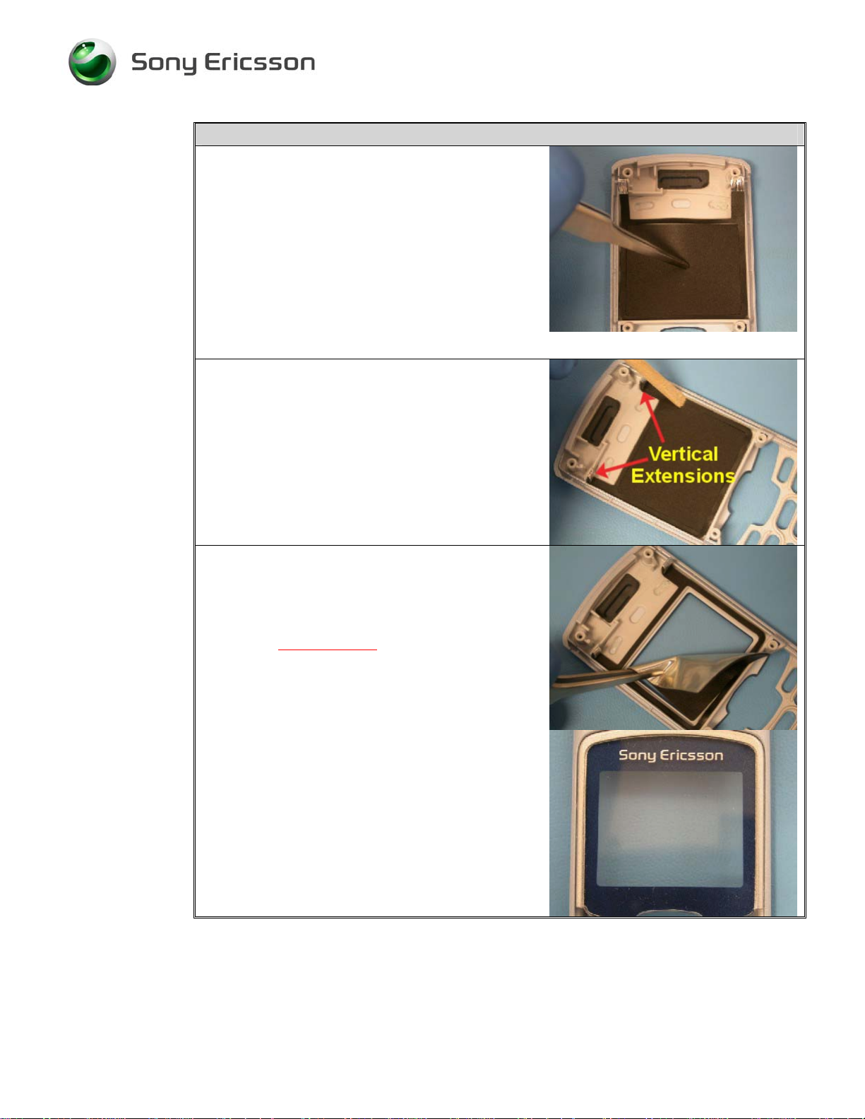
9. Remove the protective paper from the dust
gasket, but make sure to leave the paper on the
center section.
10. Holding the center section with tweezers,
carefully position the side and bottom edges of
the dust gasket adjacent to the corresponding
walls along the sides and at the bottom of the
viewing window.
NOTE! Be careful not to scratch the front cover
window with the tweezers!
11. Using the flat end of a pry tool, smooth down the
dust gasket around the window, pressing out any
air bubbles, folds, or wrinkles in the gasket.
Also press the two vertical extensions of the
gasket down into the corners and up onto the
walls they vertically adhere to.
12. Gently remove and discard the center section of
the dust gasket.
NOTE! Check to make sure that no portion of
the dust gasket is visible when viewing
straight through
the front cover window.
3/000 21-1/FEA 209 544/574 C
Sony Ericsson Mobile Communications AB
11(49)
Page 12
Working Instruction, SP/Mech
Step-by-Step Instructions
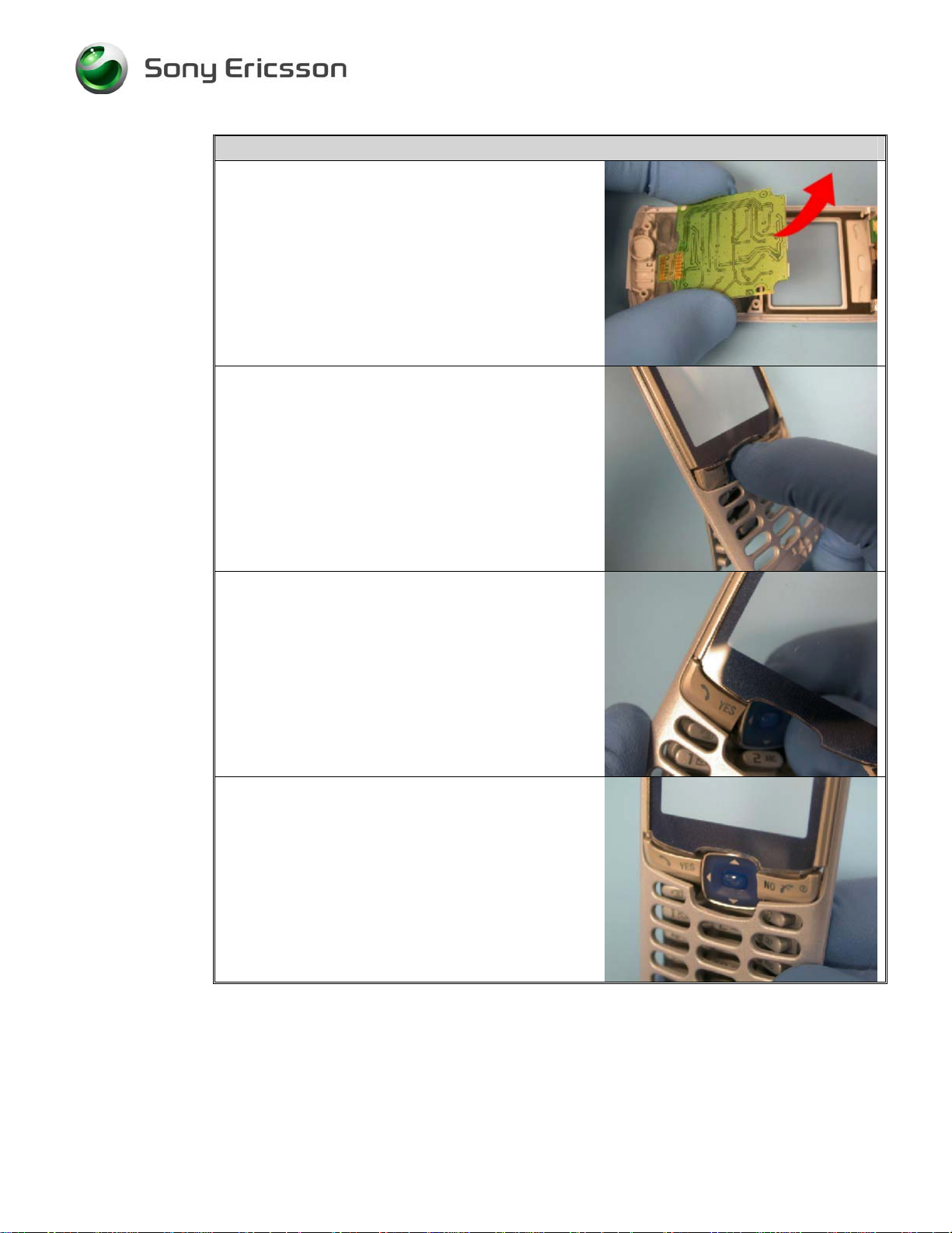
13. Lift the keypad PCB assembly out of the old
front cover.
14. Remove the keypad from the old front cover by
flexing the navigation pad inward, and pressing
out the “YES” and “NO” keys.
NOTE! Be careful not to damage the keypad by
over flexing.
15. Place the upper corner of the “Yes” key into the
appropriate location in the new front cover as
shown.
16. With the “Yes” key in place, flex the keypad so
that the “No” key will slide into its appropriate
location. Once the “Yes” and “No” keys are in
place, gently work the remaining keys into their
appropriate openings.
3/000 21-1/FEA 209 544/574 C
Sony Ericsson Mobile Communications AB
12(49)
Page 13
Working Instruction, SP/Mech
Step-by-Step Instructions
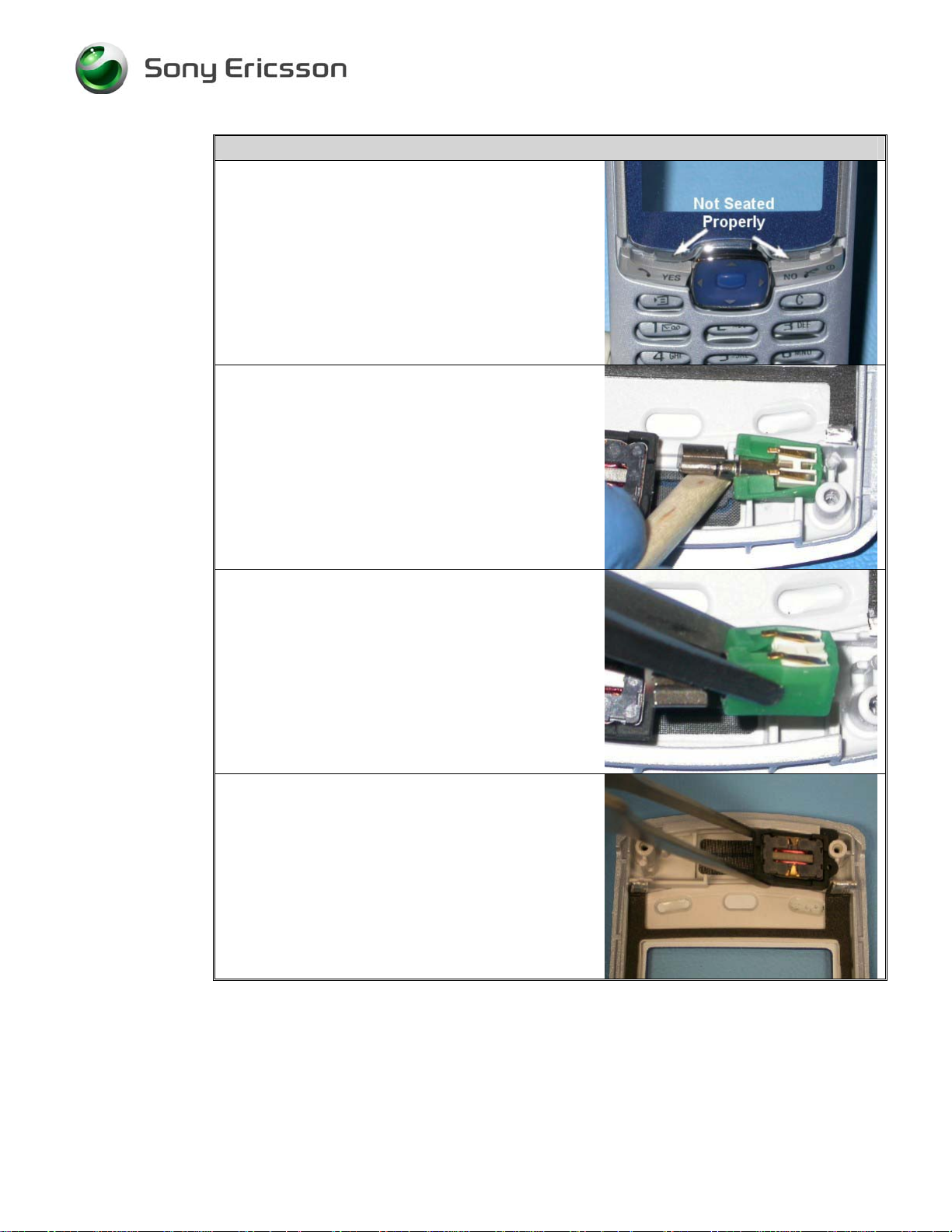
NOTE! Make sure that each key fits securely
and that the top edge of the keypad isn’t
over the edge of the front cover
window.
17. Gently pry underneath the vibrator weight to
remove it from the old front cover.
NOTE! Be careful not to damage the vibrator
contacts.
18. Place the vibrator into the new front cover as
shown. Make sure that the weight is toward the
center of the phone, and that the contacts are
facing up.
NOTE! Be careful not to damage the vibrator
contacts.
19. Remove the receiver and grommet assembly
from the old front cover.
3/000 21-1/FEA 209 544/574 C
Sony Ericsson Mobile Communications AB
13(49)
Page 14
Working Instruction, SP/Mech
Step-by-Step Instructions
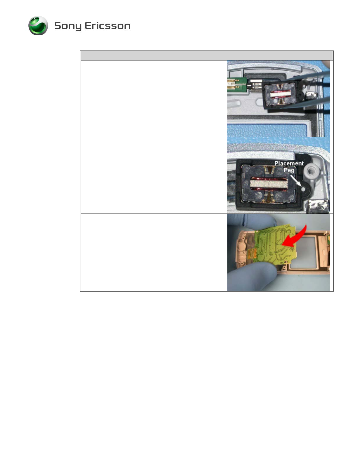
20. Place the receiver and grommet assembly into
the new front cover as shown.
NOTE! Make sure that the placement peg in the
front cover fits into the appropriate hole
in the receiver grommet.
21. Place the keypad PCB assembly into the new
front cover with the dome foil side down and the
contacts toward the bottom of the phone.
• Reassembly steps 2 – 8
3/000 21-1/FEA 209 544/574 C
Sony Ericsson Mobile Communications AB
14(49)
Page 15
Working Instruction, SP/Mech
3.2 Inlay
• Tools: Nylon pointer
• Disassembly steps 1 - 6
Step-by-Step Instructions
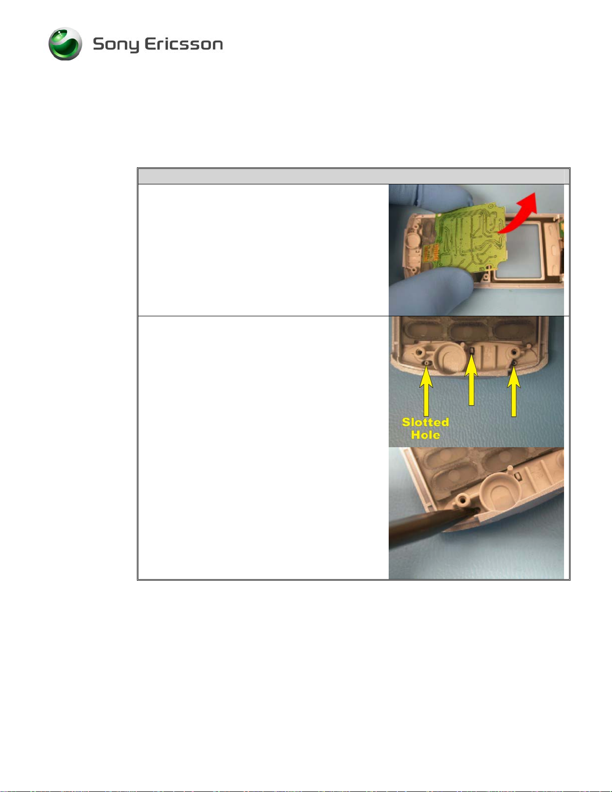
1. Lift the keypad PCB assembly out of the front
cover.
2. There are three pins that align and help hold the
inlay in place at the bottom of the front cover.
These pins can be accessed from the inside
surface of the front cover. Press out the
alignment pin that is in the slotted hole using the
pointed end of a nylon pointer.
3/000 21-1/FEA 209 544/574 C
Sony Ericsson Mobile Communications AB
15(49)
Page 16

Working Instruction, SP/Mech
Step-by-Step Instructions
3. From the outside surface of the front cover, slide
the flat end of the nylon pointer under the end of
the inlay that is now slightly raised.
4. Pry loose the inlay and remove it from the front
cover.
NOTE! Avoid scratching the front cover when
trying to remove the inlay.
5. Remove an inlay adhesive film/backing
assembly from the large strip of backing
containing the adhesive film/backing assemblies.
3/000 21-1/FEA 209 544/574 C
Sony Ericsson Mobile Communications AB
16(49)
Page 17

Working Instruction, SP/Mech
Step-by-Step Instructions
6. Place the adhesive film/backing assembly on a
new inlay and remove the backing from adhesive
film.
NOTE! The three notches in the adhesive film
should line up with the three pegs on the
inlay.
7. Alien the three pegs on the inlay up with the
corresponding holes near the bottom edge of the
front cover.
8. Apply pressure over the entire outer surface of
the inlay so that a good bond forms between the
inlay and the front cover.
3/000 21-1/FEA 209 544/574 C
Sony Ericsson Mobile Communications AB
17(49)
Page 18

Working Instruction, SP/Mech
Step-by-Step Instructions
9. Place the keypad PCB assembly into the front
cover with the dome foil side down and the
contacts toward the bottom of the phone.
• Reassembly steps 2 - 8
3/000 21-1/FEA 209 544/574 C
Sony Ericsson Mobile Communications AB
18(49)
Page 19

Working Instruction, SP/Mech
3.3 Microphone Grommet
• Tools: ESD-safe tweezers
• Disassembly steps 1 – 6
1. Remove the microphone grommet and
microphone from the microphone cavity at the
bottom of the front cover. Set the microphone
aside for safekeeping.
2. Place the old microphone into a new
microphone grommet.
NOTE! Make sure the microphone is oriented so
that the white ring on the microphone is facing
into the grommet.
3. Place the microphone assembly into the
microphone cavity at the bottom of the front
cover, with the contact side up (as shown).
• Reassembly steps 2 – 8
3/000 21-1/FEA 209 544/574 C
Sony Ericsson Mobile Communications AB
19(49)
Page 20

Working Instruction, SP/Mech
3.4 Microphone
• Tools: ESD-safe tweezers
• Disassembly steps 1 – 6
Step-by-Step Instructions
NOTE! Keep all contact surfaces clean of dirt and
hand grease! Use finger cots or gloves, and an
ESD wrist strap!
1. Remove the microphone grommet and
microphone from the cavity at the bottom of the
front cover.
2. Place a new microphone into the old microphone
grommet.
NOTE! Make sure the microphone is oriented so
that the white ring on the microphone is facing
into the grommet.
3. Place the microphone assembly into the
microphone cavity at the bottom of the front
cover, with the contact side up (as shown).
• Reassembly steps 2 – 8
3/000 21-1/FEA 209 544/574 C
Sony Ericsson Mobile Communications AB
20(49)
Page 21

Working Instruction, SP/Mech
3.5 LCD Assembly
• Tools: ESD-safe tweezers, orange stick, nylon pointer, front opening tool
NOTE! Whenever the phrase “pry tool” is used, a nylon pointer, an orange stick, or a
front opening tool may be used, depending on the user’s preference.
• Disassembly steps 1 - 8
Step-by-Step Instructions
1. Using a pry tool, dislodge the old LCD by gently
prying under its top left edge to release the
adhesive holding the LCD to the board. Once
the LCD has started coming unadhered, the LCD
should easily detach the rest of the way by hand.
NOTE! Be careful not to damage the LCD or the
flex film when prying free the LCD.
2. Once the LCD is completely unadhered, rotate
the bottom of the LCD towards the top of the
phone board to expose the flex film.
3. Remove any residual pieces of the adhesive
stripping from the phone board before
proceeding.
NOTE! If the LCD is just being temporarily
removed instead of being replaced,
avoid destroying or dirtying the
adhesive stripping along each side of the
LCD when removing the LCD or while
it is removed. Also note to ingore the
word “new” in steps 6-9 and skip step 8.
3/000 21-1/FEA 209 544/574 C
Sony Ericsson Mobile Communications AB
21(49)
Page 22

Working Instruction, SP/Mech
Step-by-Step Instructions
4. Using tweezers, push both sides of the white
retaining bar on the ZIF connector up towards
the top of the phone.
NOTE! Do not force the white retaining bar too
far up. It could become dislodged.
5. Gently slide the flex film connection upward and
out of the ZIF connector. The LCD assembly is
now free from the phone board and can be
removed or replaced as necessary.
6. To reinstall an LCD assembly, carefully slide the
flex film connection of a new LCD into the slot
between the black plastic portion of the ZIF
connector and the white retaining bar until it
reaches the bottom of the slot.
NOTE! Make sure that the white retaining bar is
still in the open position.
7. Press the white retaining bar down until it is
completely closed.
NOTE! Gently tug on the LCD flex film to
ensure that it is locked in position.
3/000 21-1/FEA 209 544/574 C
Sony Ericsson Mobile Communications AB
22(49)
Page 23

Working Instruction, SP/Mech
Step-by-Step Instructions
8. Remove the protective film from the adhesive
strips on the back of the LCD.
9. Fold the LCD down over the flex film into its
proper position against the phone board.
NOTE! The alignment pegs on the bottom of the
LCD frame should be aligned with the
appropriate holes on the phone board.
10. Once the LCD is in the correct position, gently
press the LCD against the phone board to form
an adhesive bond.
11. If present, remove the protective film from the
display portion of the LCD assembly.
• Reassembly steps 1 – 8
3/000 21-1/FEA 209 544/574 C
Sony Ericsson Mobile Communications AB
23(49)
Page 24

Working Instruction, SP/Mech
3.6 Keypad
• Disassembly steps 1 - 6
Step-by-Step Instructions
1. Lift the keypad PCB assembly out of the front
cover.
2. Remove the keypad from the old front cover by
flexing the navigation pad inward and pressing
out the “YES” and “NO” keys.
3. Install a new keypad by first placing the upper
corner of the “Yes” key into the appropriate
location in the front cover as shown.
3/000 21-1/FEA 209 544/574 C
Sony Ericsson Mobile Communications AB
24(49)
Page 25

Working Instruction, SP/Mech
Step-by-Step Instructions
4. With the “Yes” key in place, flex the keypad so
that the “No” key will slide into its appropriate
location. Once “Yes” and “No” keys are place,
gently work the remaining keys into their
appropriate openings.
NOTE! Make sure that each key fits securely
and that the top edge of the keypad isn’t
over the edge of the front cover window.
5. Place the keypad PCB assembly into the front
cover with the dome foil side down and the
contacts toward the bottom of the phone.
• Reassembly steps 2 - 8
3/000 21-1/FEA 209 544/574 C
Sony Ericsson Mobile Communications AB
25(49)
Page 26

Working Instruction, SP/Mech
3.7 Antenna/Antenna Cover Replacement
• Tools: Tools: ESD-safe tweezers, orange stick, nylon pointer, front opening tool
NOTE! Whenever the phrase “pry tool” is used, a nylon pointer, an orange stick, or a
front opening tool may be used, depending on the user’s preference.
• Disassembly steps 1 - 2
Step-by-Step Instructions
1. While lifting up the edge of the antenna cover
adjacent to the battery cavity, slide the cover
towards the top of the phone.
2. Once the antenna cover reaches the point where
it will no longer slide forward, lift the antenna
cover off of the phone.
NOTE! If replacing the antenna cover, skip to
step 9. If replacing the antenna, proceed
to step 3.
NOTE! Keep all contact surfaces clean of dirt
and hand grease! Use finger cots or
gloves, and an ESD wrist strap!
3. Use a pry tool underneath the top two tabs of the
antenna assembly to pry the old antenna
assembly loose from the back frame.
3/000 21-1/FEA 209 544/574 C
Sony Ericsson Mobile Communications AB
26(49)
Page 27

Working Instruction, SP/Mech
Step-by-Step Instructions
4. Remove the protective backing from a new
antenna assembly.
NOTE! Do not allow the adhesive film of the
antenna assembly to become
contaminated with dirt, dust, or debris.
5. Check whether the board connection portion of
the new antenna has become detached from the
antenna base. If it has become detached, press
that portion of the antenna back into place so that
it adheres to the antenna base as shown.
3/000 21-1/FEA 209 544/574 C
Sony Ericsson Mobile Communications AB
27(49)
Page 28

Working Instruction, SP/Mech
Step-by-Step Instructions
6. When placing an antenna assembly, align the
notch in the antenna assembly with the
corresponding alignment features along the top
edge of the back frame’s battery cavity.
7. Once aligned, rotate the antenna assembly down
into place on the back frame. Make sure that the
antenna assembly’s board connection fits
securely into the appropriate opening at the top
right side of the back frame.
8. Apply pressure over the entire surface of the
antenna assembly to ensure a good adhesive
bond to the back frame.
3/000 21-1/FEA 209 544/574 C
Sony Ericsson Mobile Communications AB
28(49)
Page 29

Working Instruction, SP/Mech
Step-by-Step Instructions
9. If a new antenna cover is needed:
a) Remove the backing from a SEMC icon and
place the icon in the corresponding cavity in
the new antenna cover.
NOTE! Make sure to align the peg on the icon
with its corresponding hole in the
antenna cover’s icon cavity.
b) Apply gentle pressure to the icon to ensure a
good adhesive bond to the antenna cover.
10. Place the antenna cover over the antenna so the
latches on the inside surface of the antenna cover
line up with the corresponding slots in the back
frame.
3/000 21-1/FEA 209 544/574 C
Sony Ericsson Mobile Communications AB
29(49)
Page 30

Working Instruction, SP/Mech
Step-by-Step Instructions
11. Push the antenna cover toward the bottom of the
phone until it clicks into place.
i) Check that the seams where the antenna
cover and the front cover and the
antenna cover and the back frame come
together are flush and even.
• Reassembly steps 6 - 8
3/000 21-1/FEA 209 544/574 C
Sony Ericsson Mobile Communications AB
30(49)
Page 31

Working Instruction, SP/Mech
3.8 SEMC Icon
• Tools: Tools: ESD-safe tweezers, nylon pointer
• Disassembly steps 1- 4
Step-by-Step Instructions
1. Looking at the inside surface of the antenna
cover, locate the SEMC icon’s alignment pin.
Press the alignment pin out of the hole in the
antenna cover. This can be accomplished by
using the pointed end of a nylon pointer.
2. Slide the flat end of the nylon pointer under the
icon’s lifted edge and pry the icon out of the
cavity in the antenna cover.
NOTE! Avoid scratching the antenna cover
when trying to remove the icon.
3. Remove the backing from a new SEMC icon and
place the icon in the corresponding cavity in the
antenna cover.
NOTE! Make sure to align the peg on the icon
with its corresponding hole in the
antenna cover’s icon cavity.
3/000 21-1/FEA 209 544/574 C
Sony Ericsson Mobile Communications AB
31(49)
Page 32

Working Instruction, SP/Mech
Step-by-Step Instructions
4. Apply gentle pressure to the icon to ensure a
good adhesive bond to the antenna cover.
• Reassembly steps 4 - 8
3/000 21-1/FEA 209 544/574 C
Sony Ericsson Mobile Communications AB
32(49)
Page 33

Working Instruction, SP/Mech
3.9 Keypad PCB Assembly
• Disassembly steps 1 - 6
Step-by-Step Instructions
1. Lift the old keypad PCB assembly out of the
front cover.
2. Place a new keypad PCB assembly into the front
cover with the dome foil side oriented towards
the front cover and the contact pads on the
keypad PCB assembly oriented toward the
bottom of the phone.
• Reassembly steps 2 - 8
3/000 21-1/FEA 209 544/574 C
Sony Ericsson Mobile Communications AB
33(49)
Page 34

Working Instruction, SP/Mech
3.10 Receiver and Receiver Gasket
• Tools: ESD-safe tweezers
• Disassembly steps 1- 6
Step-by-Step Instructions
NOTE! Keep all contact surfaces clean of dirt
and hand grease! Use finger cots or
gloves, and an ESD wrist strap!
1. Remove the old receiver and receiver gasket
from the front cover.
2. Separate the receiver from the receiver gasket.
3. Replace the receiver and/or the receiver gasket
as necessary.
4. Mount the good receiver into the good receiver
gasket. The receiver’s contacts should be facing
out.
NOTE! Be careful not to damage the contacts.
3/000 21-1/FEA 209 544/574 C
Sony Ericsson Mobile Communications AB
34(49)
Page 35

Working Instruction, SP/Mech
Step-by-Step Instructions
5. Place the good receiver/gasket assembly into the
front cover.
NOTE! Make sure that the placement peg in the
front cover fits into the appropriate hole
in the receiver gasket.
• Reassembly steps 2 - 8
3/000 21-1/FEA 209 544/574 C
Sony Ericsson Mobile Communications AB
35(49)
Page 36

Working Instruction, SP/Mech
3.11 Polyphonic Speaker and Speaker Grommet
• Tools: ESD-safe tweezers
• Disassembly steps 1 - 8
Step-by-Step Instructions
NOTE! Keep all contact surfaces clean of dirt
and hand grease! Use finger cots or
gloves, and an ESD wrist strap!
1. Remove the polyphonic speaker/grommet
assembly from the back frame.
2. Separate the polyphonic speaker from its
grommet.
3. Replace the polyphonic speaker and/or the
speaker grommet as necessary.
4. Install the good speaker into the good speaker
grommet. The speaker’s contacts should be
oriented so that they line up with the
corresponding notch in the grommet.
NOTE! Make sure that the lips of the grommet
are overlapping the speaker.
5. If the polyphonic speaker was replaced, install a
speaker pad over the back of the new speaker as
shown.
3/000 21-1/FEA 209 544/574 C
Sony Ericsson Mobile Communications AB
36(49)
Page 37

Working Instruction, SP/Mech
Step-by-Step Instructions
6. Place the speaker/grommet assembly into its
appropriate cavity in the back frame.
NOTE! Look through the buzzer sound opening
on the side of the back frame and make
sure that the grommet is not blocking the
opening.
• Reassembly steps 1- 8
3/000 21-1/FEA 209 544/574 C
Sony Ericsson Mobile Communications AB
37(49)
Page 38

Working Instruction, SP/Mech
3.12 Volume Switch and/or Volume Button
• Tools: ESD-safe tweezers
• Disassembly steps 1- 8
Step-by-Step Instructions
NOTE! Keep all contact surfaces clean of dirt
and hand grease! Use finger cots or
gloves, and an ESD wrist strap!
1. Using tweezers, gently pull the volume switch
out of the back frame.
NOTE! If only the volume switch is being
replaced, skip to step 5. If replacing the
volume button, proceed to step 2.
2. From the portion of the volume button that is
externally accessible, press the volume button
inward and upward (away from the antenna) to
dislodge it from its position in the back frame.
3. From the inside of the back frame, lift the
volume button out of its cavity.
3/000 21-1/FEA 209 544/574 C
Sony Ericsson Mobile Communications AB
38(49)
Page 39

Working Instruction, SP/Mech
Step-by-Step Instructions
4. Place a new volume button into the cavity and
push the retaining hole down onto the alignment
peg inside of the cavity.
NOTE! Make sure that the button is oriented
properly. The contour of the button and
its exterior access hole in the back frame
should match.
3/000 21-1/FEA 209 544/574 C
Sony Ericsson Mobile Communications AB
39(49)
Page 40

Working Instruction, SP/Mech
Step-by-Step Instructions
5. Replace the old volume switch if determined to
be necessary.
NOTE! The contacts should be facing out
toward the wall of the back frame.
6. Push the volume switch into the gap behind the
volume button.
NOTE! Be careful not to bend or damage the
spring fingers on the volume switch
when installing it.
• Reassembly steps 1 - 8
3/000 21-1/FEA 209 544/574 C
Sony Ericsson Mobile Communications AB
40(49)
Page 41

Working Instruction, SP/Mech
3.13 Vibrator
• Tools: ESD-safe tweezers, orange stick, nylon pointer, front opening tool
NOTE! Whenever the phrase “pry tool” is used, a nylon pointer, an orange stick, or a
front opening tool may be used, depending on the user’s preference.
• Disassembly steps 1- 6
Step-by-Step Instructions
NOTE! Keep all contact surfaces clean of dirt
and hand grease! Use finger cots or
gloves, and an ESD wrist strap!
1. Gently pry underneath the vibrator weight to
remove it from the front cover.
2. Place a new vibrator into the front cover as
shown. Make sure that the weight is toward the
center of the phone, and that the contacts are
facing up.
NOTE! Be careful not to damage the vibrator
contacts.
• Reassembly steps 2 - 8
3/000 21-1/FEA 209 544/574 C
Sony Ericsson Mobile Communications AB
41(49)
Page 42

Working Instruction, SP/Mech
3.14 Label Replacement
• Tools: ESD-safe tweezers, hot air gun
• Disassembly steps 1- 2
Step-by-Step Instructions
NOTE! This instruction should be used when
exchanging an old label or mounting a
new one.
1. Print a new label.
NOTE! The text must be fully readable manually
and mechanically.
NOTE! If one label or less is present on the
phone, proceed to step 3. If two or more
labels are on the phone, proceed to Step
2.
2. Carefully remove the old labels.
NOTE! If difficulty in removing the old labels is
experienced, try heating up the old
label(s) with a hot air gun to loosen the
adhesive bond.
NOTE! Avoid scratching the frame when trying
to peel off of the labels.
NOTE! Make sure that all adhesive residue is
removed. Carefully clean off any
residue in the label area.
NOTE! No more than two labels are allowed
on the battery cavity.
3. Place the new label into the battery cavity.
Center the label so that the notches in the label
are lined up to the center screw openings, the
battery connection at the top of the battery
cavity, and the edges of the SIM card opening.
4. Once the label is correctly positioned, carefully
smooth the label into place.
• Reassembly steps 6 - 8
3/000 21-1/FEA 209 544/574 C
Sony Ericsson Mobile Communications AB
42(49)
Page 43

Working Instruction, SP/Mech
3.15 Frame Replacement
• Tools: ESD-safe tweezers, orange stick, nylon pointer, front opening tool
NOTE! Whenever the phrase “pry tool” is used, a nylon pointer, an orange stick, or a
front opening tool may be used, depending on the user’s preference.
• Disassembly steps 1 - 8
Step-by-Step Instructions
NOTE! Keep all contact surfaces clean of dirt
and hand grease! Use finger cots or
gloves, and an ESD wrist strap!
1. Use a pry tool underneath the top two tabs of the
antenna assembly to pry it loose from the old
back frame.
NOTE! Do not allow the adhesive film of the
antenna assembly to become
contaminated with dirt, dust, or debris
while the antenna assembly is removed.
3/000 21-1/FEA 209 544/574 C
Sony Ericsson Mobile Communications AB
43(49)
Page 44

Working Instruction, SP/Mech
Step-by-Step Instructions
2. Before installing the antenna assembly onto
the new back frame, check whether the
board connection portion of the antenna has
become detached from the antenna base. If
it has become detached, press that portion of
the antenna back into place so that it adheres
to the antenna base as shown.
3/000 21-1/FEA 209 544/574 C
Sony Ericsson Mobile Communications AB
44(49)
Page 45

Working Instruction, SP/Mech
Step-by-Step Instructions
3. When placing the antenna assembly, align the
notch in the antenna assembly with the
corresponding alignment features along the top
edge of the new back frame’s battery cavity.
4. Once aligned, rotate the antenna assembly down
into place on the back frame. Make sure that the
board connection portion of the antenna
assembly fits securely into the appropriate
opening at the top right side of the back frame.
5. Apply pressure over the entire surface of the
antenna assembly to ensure a good adhesive
bond to the back frame.
6. Remove the polyphonic speaker/grommet
assembly from the old back frame.
3/000 21-1/FEA 209 544/574 C
Sony Ericsson Mobile Communications AB
45(49)
Page 46

Working Instruction, SP/Mech
Step-by-Step Instructions
7. Place the polyphonic speaker/grommet
assembly into its appropriate cavity in the new
back frame.
NOTE! Look through the buzzer sound opening
on the side of the back frame and make
sure that the grommet is not blocking
the opening.
8. Using tweezers, gently pull the volume switch
out of the old back frame.
NOTE! Be careful not to bend or damage the
spring fingers.
3/000 21-1/FEA 209 544/574 C
Sony Ericsson Mobile Communications AB
46(49)
Page 47

Working Instruction, SP/Mech
Step-by-Step Instructions
9. From the portion of the volume button that is
externally accessible, press the volume button
inward and upward (away from the side of the
back frame the antenna attaches too) to
dislodge it from its position in the back frame.
10. From the inside of the back frame, lift the
volume button out of its cavity.
3/000 21-1/FEA 209 544/574 C
Sony Ericsson Mobile Communications AB
47(49)
Page 48

Working Instruction, SP/Mech
Step-by-Step Instructions
11. Place the volume button into the appropriate
cavity in the new back frame and push the
retaining hole down onto the alignment peg
inside of the cavity.
NOTE! Make sure that the button is oriented
properly. The contour of the button and
its exterior access hole in the back
frame should match.
3/000 21-1/FEA 209 544/574 C
Sony Ericsson Mobile Communications AB
48(49)
Page 49

Working Instruction, SP/Mech
Step-by-Step Instructions
NOTE! The volume switch’s contacts should be
facing out toward the wall of the back
frame.
12. Push the volume switch into the gap behind the
volume button.
NOTE! Be careful not to bend or damage the
spring fingers on the volume switch
when installing it.
13. Print a new label.
NOTE! The text must be fully readable
manually and mechanically.
14. Place the new label into the battery cavity.
Center the label so that the notches in the label
are lined up to the center screw openings, the
battery connection at the top of the battery
cavity, and the edges of the SIM card opening.
15. Once the label is correctly positioned, carefully
smooth the label into place.
• Reassembly steps 1 - 8
4 Revision History
Rev. Date Changes / Comments
PA1 2003-05-20 First draft
A 2003-08-04 Initial Release
B 2003-09-16
C 2003-10-31
• Added “front opening tool” option where applicable
• Updated content to clarify document
• Removed shield can inspection
• Removed mandatory replacement of microphone grommet. Mandatory
replacement is no longer required. Replace as necessary.
3/000 21-1/FEA 209 544/574 C
Sony Ericsson Mobile Communications AB
49(49)
 Loading...