

Page 1

Trouble Shooting Guide, Mechanical
Trouble Shooting Guide, Mechanical
Applicable for S700i, S700c
Contents
1
Explanations ....................................................................................................................2
1.1 Service functions in the software.......................................................................2
1.2 Misuse and other no warranty issues.................................................................2
1.2.1 Action ................................................................................................................ 2
1.2.2 Water indicator label .........................................................................................4
1.2.3 Action ................................................................................................................ 5
2 Appearance Problem ...................................................................................................... 6
3 Alert Problem ..................................................................................................................9
3.1 Vibrator .............................................................................................................9
3.2 Speaker .............................................................................................................. 9
4 Audio Problem ..............................................................................................................11
4.1 Receiver...........................................................................................................11
4.2 Microphone......................................................................................................11
5 Charging/Capacity........................................................................................................13
5.1 Charging .......................................................................................................... 13
5.2 Capacity...........................................................................................................13
6 Data Communication Problem .................................................................................... 13
7 Key/Flip..........................................................................................................................14
7.1 Keyboard .........................................................................................................14
7.2 Side keys..........................................................................................................15
7.3 Hinge ............................................................................................................... 16
8 LCD/Illumination.......................................................................................................... 18
8.1 LCD .................................................................................................................18
8.2 Illumination .....................................................................................................18
8.2.1 Main keyboard................................................................................................. 18
8.2.2 Navigation keys ...............................................................................................19
9 Network..........................................................................................................................20
10 On/Off ............................................................................................................................21
10.1 Battery .............................................................................................................21
10.2 On/Off key....................................................................................................... 21
11 Other ..............................................................................................................................23
11.1 Camera Problem .............................................................................................. 23
11.2 Camera shutter................................................................................................. 23
12 Software Problem..........................................................................................................25
13 Revision History............................................................................................................ 26
4/00021-1/FEA 209 544/89 A
Company Internal
Sony Ericsson Mobile Communications AB
Approved according to 000 21-LXE 107 42/1
Page 2

Trouble Shooting Guide, Mechanical
1 Explanations
1.1 Service functions in the software
The service menu will be accessed with the following key combination. Use the joystick.
⇒*⇐⇐*⇐*
They are as follows:
Service info
Service tests
Text labels
The phones software has a built in service functionality that allows you to test some of the
phones functions. (See point 2 above) It looks like this:
Main display
Camera
LED/illumination
Flash LED
Keyboard
Vibrator
Earphone
Speaker
Microphone
Real time clock
FM radio (You need a headset to test)
Total call time
1.2 Misuse and other no warranty issues
Misuse is not covered by warranty. This chapter will explain what’s not covered by warranty.
Phones that have been exposed to misuse will not be covered by warranty.
This means: if it is possible to repair the phone, the customer will have to pay for the repair.
SEMC will not allow any of these phones to be claimed into WCMS. Some local perspectives
may interfere with this. Please reference to local directives.
1.2.1 Action
Make a general visual inspection for misuse.
Below are some examples of what is not covered by warranty.
4/00021-1/FEA 209 544/89 A
Company Internal
Sony Ericsson Mobile Communications AB
2(26)
Page 3

Trouble Shooting Guide, Mechanical
Front window broken due
to misuse.
LCD cracked due to
drop.
Clear scratches
Mark after drop Plugs are not covered by warranty.
Corrosion components on the
PCB.
System connector damaged by
liquid
4/00021-1/FEA 209 544/89 A
Company Internal
Sony Ericsson Mobile Communications AB
Corrosion components on the
PCB.
Components around system
connector damaged by liquid
SIM reader damaged by
liquid.
System connector pad(s) damaged
by liquid
3(26)
Page 4
Trouble Shooting Guide, Mechanical
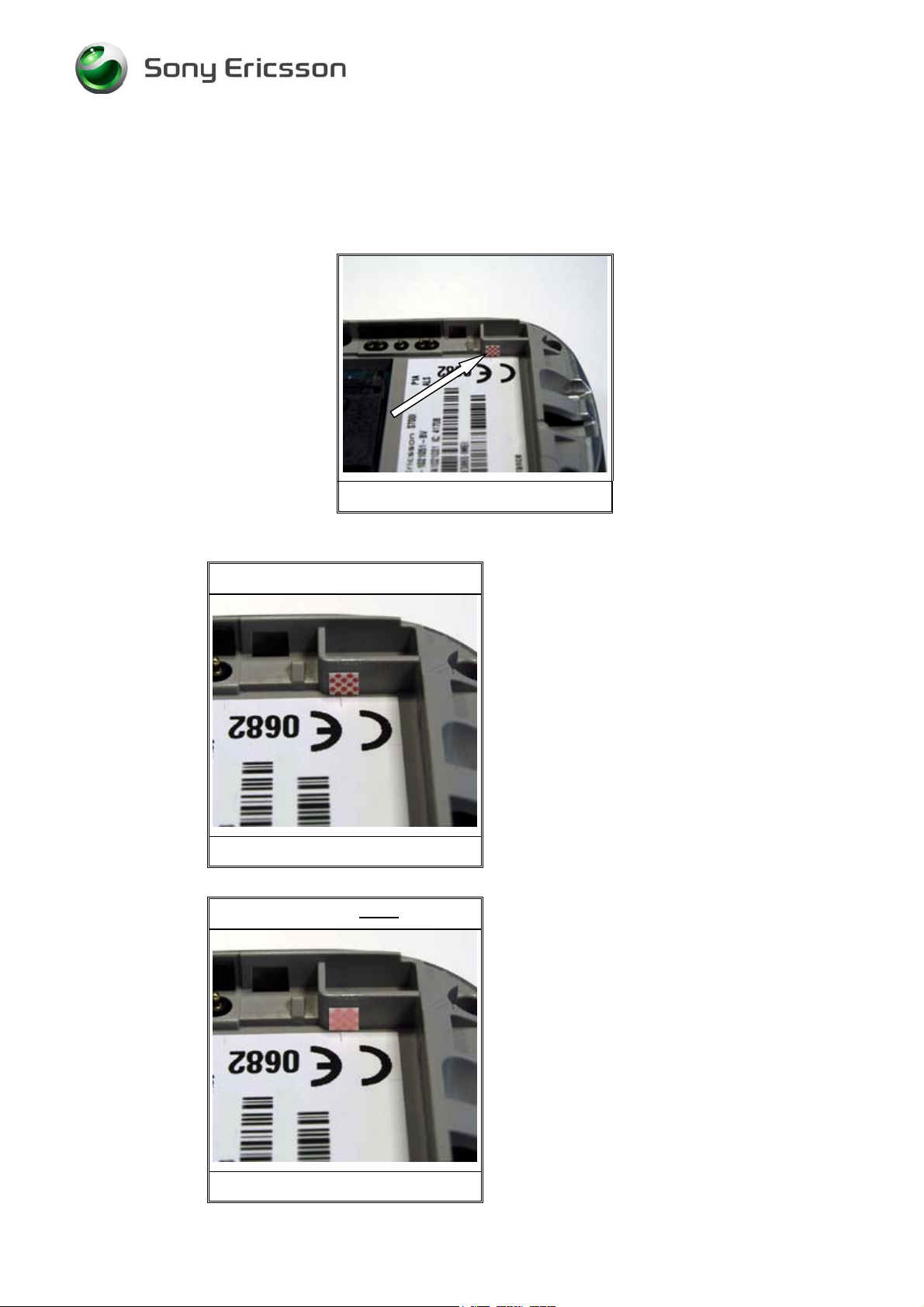
1.2.2 Water indicator label
In the phone there is placed a sticker that can give you a hint to see if the phone is damage by
liquid or not. This sticker is located near the type label (Fig. 1.2.1) and it is possible to see it
without disassemble the phone.
Fig. 1.2.1
On the pictures below you will see the different between a sticker that has been in contact
with liquid (Fig. 1.2.3) and with one that hasn’t (Fig. 1.2.2).
This sticker is ok
This sticker has not been in contact with
liquid.
Fig. 1.2.2
This sticker is not
ok
This sticker has been in contact with liquid. As you
can see it has turn into a red or pink label. In this
case you should check the phone for liquid damage
(See point 1.2.2).
Note: There must be clear marks after liquid on the
PCB before rejecting the phone for repair.
4/00021-1/FEA 209 544/89 A
Company Internal
Sony Ericsson Mobile Communications AB
Fig. 1.2.3
4(26)
Page 5

Trouble Shooting Guide, Mechanical
1.2.3 Action
Make a general visual inspection for corrosion or oxidation from liquid damage. No further
action should be taken for a liquid damaged phone. Handle the unit according to local
directives.
4/00021-1/FEA 209 544/89 A
Company Internal
Sony Ericsson Mobile Communications AB
5(26)
Page 6
Trouble Shooting Guide, Mechanical
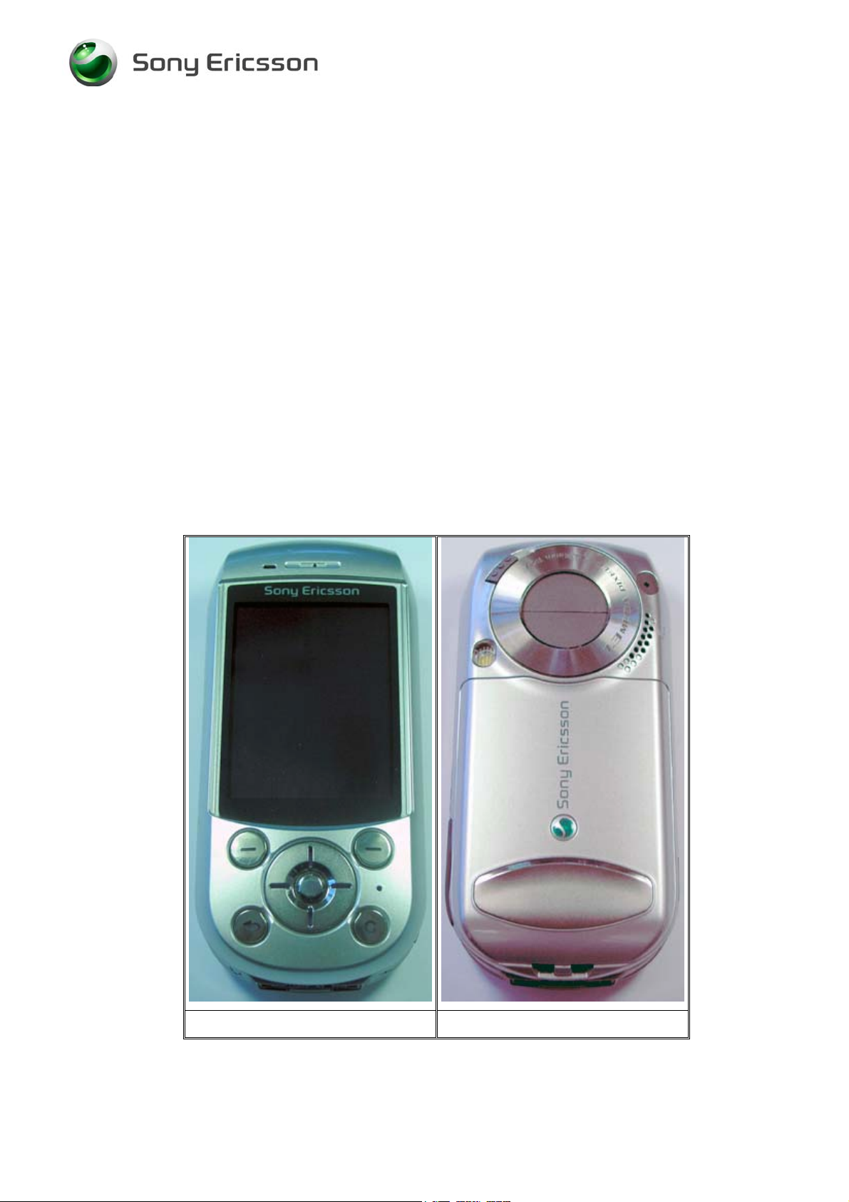
2 Appearance Problem
• Make a general visual inspection for misuse, corrosion or oxidation from liquid damage
according to point 1.2
• Check the Case LCD front (Fig. 2.1), the Case Key rear (Fig. 2.2), the Case LCD rear
(Fig. 2.3), the Case Key front (Fig. 2.4) The Panel LCD rear (Fig. 2.3), the Panel LCD
front (Fig. 2.4) and the battery cover (Fig. 2.2) for damage, scratches and if the parts fit
correct. Replace the faulty component(s) if necessary.
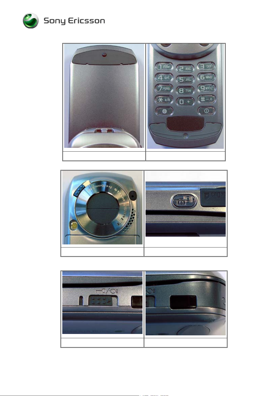
• Check the Panel Camera, (Fig. 2.5) and the Cover Camera left and right (Fig. 2.5) for
damage, scratches and if the parts fit correct. Replace the faulty component(s) if
necessary.
• Check the button key (Fig. 2.4), the button LCD top, side and centre (Fig. 2.1), the button
shutter (Fig. 2.6) and the button lock switch (Fig.2.7) for damage, scratches and if the
parts fit correct. Replace the faulty component(s) if necessary.
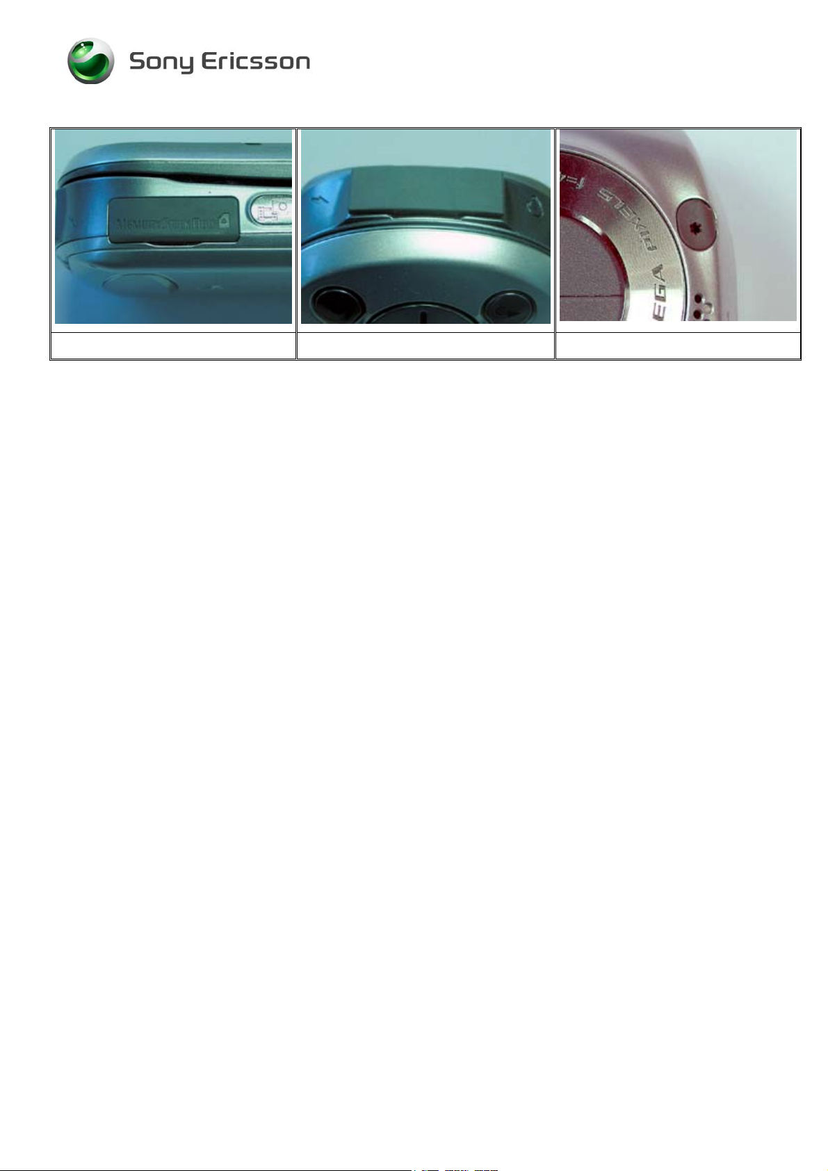
• Check the panel IRDA (Fig. 2.8), the light guide (Fig. 2.7), the cover MS (Fig. 2.9), the
cover system connector I/O (Fig. 2.10) and the cover R/F (Fig. 2.11) for damage, scratches
and if the parts fit correct. Replace the faulty component(s) if necessary.
If the failure still occurs, handle the unit according to the local directives.
4/00021-1/FEA 209 544/89 A
Company Internal
Sony Ericsson Mobile Communications AB
Fig. 2.1 Fig. 2.2
6(26)
Page 7
Trouble Shooting Guide, Mechanical
Fig. 2.3 Fig. 2.4
Fig. 2.5 Fig.2.6
4/00021-1/FEA 209 544/89 A
Company Internal
Sony Ericsson Mobile Communications AB
Fig. 2.7 Fig.2.8
7(26)
Page 8
Trouble Shooting Guide, Mechanical
Fig. 2.9 Fig. 2.10 Fig. 2.11
4/00021-1/FEA 209 544/89 A
Company Internal
Sony Ericsson Mobile Communications AB
8(26)
Page 9

Trouble Shooting Guide, Mechanical
3 Alert Problem
• Make a general visual inspection for misuse, corrosion or oxidation from liquid damage
according to point 1.2
3.1 Vibrator
• Turn on the phone. Go to the service test menu; choose “Vibrator”. Press any key to check
the vibrator works properly.
• Check if the vibrator pads (Fig. 3.1) are dirty or oxidized. Clean them if necessary.
• Check if the vibrator (Fig. 3.2) is mechanical damaged, dirty or oxidized. Replace it if
necessary.
• Check if the Frame RF (Fig. 3.3) is mechanical damaged. Replace it if necessary.
If the fault still occurs, try to update the phone to the latest available software version. If this
doesn’t solve the problem, handle the unit according to the local directives.
Fig. 3.1 Fig. 3.2 Fig. 3.3
3.2 Speaker
• Turn on the phone. Go to the service test menu; choose “Speaker”. Press any key to check
the speaker works properly.
• Check if the keyboard flex-film is fitting correct into the FPC connector (Fig. 3.4) and
check if the FPC connector is closed.
• Check if the key FPC (Fig. 3.5) is mechanical damage, dirty or oxidized. Replace it if
necessary.
If the fault still occurs, try to update the phone to the latest available software version. If this
doesn’t solve the problem, handle the unit according to the local directives.
4/00021-1/FEA 209 544/89 A
Company Internal
Sony Ericsson Mobile Communications AB
9(26)
Page 10

Trouble Shooting Guide, Mechanical
Fig. 3.4 Fig. 3.5
4/00021-1/FEA 209 544/89 A
Company Internal
Sony Ericsson Mobile Communications AB
10(26)
Page 11

Trouble Shooting Guide, Mechanical
4 Audio Problem
• Make a general visual inspection for misuse, corrosion or oxidation from liquid damage
according to point 1.2
4.1 Receiver
• Turn on the phone. Go to the service test menu; choose “Earphone” press any key to check
the speaker works properly.
• Check if the receiver pads (Fig. 4.1) is dirty or oxidized. Clean or replace the FPC hinge if
necessary.
• Check if the receiver (Fig. 4.2) is mechanical damaged, dirty or oxidized. Replace it if
necessary.
If the fault still occurs, try to update the phone to the latest available software version. If this
doesn’t solve the problem, handle the unit according to the local directives.
Fig. 4.1 Fig. 4.2
4.2 Microphone
• Turn on the phone. Go to the service test menu; choose “Microphone”. Check if the
microphone works properly.
• Check if the microphone pads (Fig. 4.3) are dirty or oxidized. Clean or replace the FPC
hinge if necessary.
• Check if the microphone (Fig. 4.4) is mechanical damaged, dirty or oxidized. Replace it if
necessary.
If the fault still occurs, try to update the phone to the latest available software version. If this
doesn’t solve the problem, handle the unit according to the local directives.
4/00021-1/FEA 209 544/89 A
Company Internal
Sony Ericsson Mobile Communications AB
11(26)
Page 12

Trouble Shooting Guide, Mechanical
Fig. 4.3 Fig. 4.4
4/00021-1/FEA 209 544/89 A
Company Internal
Sony Ericsson Mobile Communications AB
12(26)
Page 13

Trouble Shooting Guide, Mechanical
5 Charging/Capacity
• Make a general visual inspection for misuse, corrosion or oxidation from liquid damage
according to point 1.2
5.1 Charging
• Insert a working battery and connect a working charger to the phone. If the battery voltage
is too low the phone will charge the battery without turning on the phone (this will usually
take less than 10 minutes) and when the battery voltage is high enough the phone will be
able to turn on and show charging in the LCD.
• Check if the system connector (Fig 6.1) is mechanical damaged, dirty or oxidized. Replace
it if necessary.
If the fault still occurs, try to update the phone to the latest available software version. If this
doesn’t solve the problem, handle the unit according to the local directives.
5.2 Capacity
• The standby time will be reduced if, the light is turned on all the time, the bluetooth is
turned on, or if the infrared is turned on.
6 Data Communication Problem
• Make a general visual inspection for misuse, corrosion or oxidation from liquid damage
according to point 1.2
• If there is a problem with the communication through the system connector, e.g. if it is not
possible to synchronizing with MS Outlook, check if the system connector (Fig. 6.1) is
mechanical damaged, dirty or oxidized. Replace it if necessary.
• Check if there is a problem with bluetooth communication. Replace the BT Antenna (Fig.
6.2) if necessary.
If the fault still occurs, try to update the phone to the latest available software version. If this
doesn’t solve the problem, handle the unit according to the local directives.
4/00021-1/FEA 209 544/89 A
Company Internal
Sony Ericsson Mobile Communications AB
Fig. 6.1 Fig. 6.2
13(26)
Page 14

Trouble Shooting Guide, Mechanical
7 Key/Flip
• Make a general visual inspection for misuse, corrosion or oxidation from liquid damage
according to point 1.2
7.1 Keyboard
• Turn on the phone. Go to the service test menu; choose “Keyboard”. Press all the keys.
The pressed key will be indicated in the LCD and a DTMF tone is heard.
• Check if the mechanically response feels normal and that all the keys have been showed in
the LCD.
• Check if the button LCD top, side, base and centre (Fig. 7.1) or the button key (Fig. 7.2) is
mechanical damaged or dirty. Replace the faulty necessary.
• Check if the key flex sheet (Fig. 7.3) or the LCD flex sheet (Fig.7.4) is mechanical
damaged, dirty or oxidized. Replace the faulty component if necessary.
• Check if the key FPC (Fig. 7.5) or the FPC hinge (Fig.7.6) is mechanical damaged, dirty
or oxidized. Replace the faulty component if necessary.
• Check if the keyboard flex-film is fitting correct into the FPC connector (Fig. 7.7) and
check if the FPC connector is closed.
If the fault still occurs, try to update the phone to the latest available software version. If this
doesn’t solve the problem, handle the unit according to the local directives.
4/00021-1/FEA 209 544/89 A
Company Internal
Sony Ericsson Mobile Communications AB
Fig. 7.1 Fig. 7.2
14(26)
Page 15

Trouble Shooting Guide, Mechanical
Fig. 7.3 Fig. 7.4 Fig. 7.5
Fig. 7.6 Fig. 7.7
7.2 Side keys
• Turn on the phone. Go to the service test menu; choose “Keyboard”. Press all the side
keys. The pressed key will be indicated in the LCD and a DTMF tone is heard.
• Check if the Button lock switch (Fig. 7.8) and the button shutter (Fig.7.9) is working
properly and if the mechanical response feels normal. Replace the faulty component if
necessary.
• Check if the key flex sheet (Fig. 7.10) is mechanical damaged, dirty or oxidized. Replace
it if necessary.
• Check if the key FPC (Fig. 7.11) is mechanical damaged, dirty or oxidized. Replace it if
necessary.
• Check if the FPC Connectors (Fig. 7.12) are closed properly and if the flex films are
mounted right in the FPC connectors.
If the fault still occurs, try to update the phone to the latest available software version. If this
doesn’t solve the problem, handle the unit according to the local directives.
4/00021-1/FEA 209 544/89 A
Company Internal
Sony Ericsson Mobile Communications AB
15(26)
Page 16

Trouble Shooting Guide, Mechanical
Fig. 7.8 Fig. 7.9
Fig. 7.10 Fig. 7.11 Fig. 7.12
7.3 Hinge
• Check if the mechanically response feels normal and if the hinge is loose. Replace the
hinge (Fig. 7.13), the panel LCD rear (Fig. 7.14) or the panel LCD front (Fig. 7.15) if
necessary.
• Check if the electrical response when opening the flip works. Replace the magnet (Fig.
7.16) if necessary. If the fault still occurs replace the key FPC (Fig. 7.17).
If the fault still occurs, try to update the phone to the latest available software version. If this
doesn’t solve the problem, handle the unit according to the local directives.
4/00021-1/FEA 209 544/89 A
Company Internal
Sony Ericsson Mobile Communications AB
Fig. 7.13 Fig. 7.14
16(26)
Page 17

Trouble Shooting Guide, Mechanical
Fig. 7.15 Fig. 7.16 Fig. 7.17
4/00021-1/FEA 209 544/89 A
Company Internal
Sony Ericsson Mobile Communications AB
17(26)
Page 18

Trouble Shooting Guide, Mechanical
8 LCD/Illumination
• Make a general visual inspection for misuse, corrosion or oxidation from liquid damage
according to point 1.2
8.1 LCD
• Turn on the phone. Go to service test menu; choose “Display”. You should see a colour
pattern.
• Check if the LCD unit (Fig. 8.1) works properly and if there are missing lines or
discolours. Replace it if necessary.
• Check if the LCD flex-film is fitting correct into the FPC connector (Fig. 8.2) and check if
the FPC connector is closed.
• Check if the harness (Fig. 8.3) is mechanical damaged, dirty or oxidized. Replace it if
necessary.
If the fault still occurs, try to update the phone to the latest available software version. If this
doesn’t solve the problem, handle the unit according to the local directives.
Fig. 8.1 Fig. 8.2 Fig. 8.3
8.2 Illumination
• Turn on the phone. Go to service test menu; choose “LED/Illumination”. The illumination
should start blinking ~1Hz.
• Check if the LCD unit (Fig. 8.1) is lighting up properly. Replace it if necessary.
• Check if the harness (Fig. 8.3) is mechanical damaged, dirty or oxidized. Replace it if
necessary.
8.2.1 Main keyboard
4/00021-1/FEA 209 544/89 A
Company Internal
Sony Ericsson Mobile Communications AB
18(26)
Page 19

Trouble Shooting Guide, Mechanical
• Check if the entire 10 key LED’s (Fig. 8.5) is lighting in the same strength. Replace the
key FPC if necessary.
• Check if the key FPC is fitting correct into the FPC connector (Fig. 8.4) and check if the
FPC connector is closed.
8.2.2 Navigation keys
• Check if the entire 4 key LED’s (Fig. 8.6) is lighting in the same strength. Replace the
FPC hinge if necessary.
• Check if the harness (Fig. 8.3) is mechanical damaged, dirty or oxidized. Replace it if
necessary.
If the fault still occurs, try to update the phone to the latest available software version. If this
doesn’t solve the problem, handle the unit according to the local directives.
Fig. 8.4 Fig. 8.5 Fig. 8.6
4/00021-1/FEA 209 544/89 A
Company Internal
Sony Ericsson Mobile Communications AB
19(26)
Page 20

Trouble Shooting Guide, Mechanical
9 Network
• Make a general visual inspection for misuse, corrosion or oxidation from liquid damage
according to point 1.2
• Insert a correct working SIM-card in the phone and turn it on. Check if the phone gets
service and if the signal strength indicator shows a correct value at the display. Compare
the value with a working phone.
• Check if the antenna flex (Fig. 9.1-9.2) is mechanical damaged, dirty or oxidized. Replace
it if necessary.
If the fault still occurs, try to update the phone to the latest available software version. If this
doesn’t solve the problem, handle the unit according to the local directives.
Fig. 9.1 Fig. 9.2
4/00021-1/FEA 209 544/89 A
Company Internal
Sony Ericsson Mobile Communications AB
20(26)
Page 21

Trouble Shooting Guide, Mechanical
10 On/Off
• Make a general visual inspection for misuse, corrosion or oxidation from liquid damage
according to point 1.2
10.1 Battery
• Insert a working battery and connect a working charger to the phone. If the battery voltage
is too low the phone will charge the battery without turning on the phone (this will usually
take less than 10 minutes) and when the battery voltage is high enough the phone will be
able to turn on and show charging in the LCD.
If the fault still occurs, try to update the phone to the latest available software version. If this
doesn’t solve the problem, handle the unit according to the local directives.
10.2 On/Off key
• Insert a fully charged battery and turn the phone on. If it fails;
• Check if the button key (Fig. 10.1) is mechanical damaged or dirty. Replace it if
necessary.
• Check if the key flex sheet (Fig. 10.2) is mechanical damaged, dirty or oxidized. Replace
it if necessary.
• Check if the key FPC (Fig. 10.3) is mechanical damaged, dirty or oxidized. Replace it if
necessary.
• Check if the keyboard flex-film is fitting correct into the FPC connector (Fig. 10.5) and
check if the FPC connector is closed.
If the fault still occurs, try to update the phone to the latest available software version. If this
doesn’t solve the problem, handle the unit according to the local directives.
4/00021-1/FEA 209 544/89 A
Company Internal
Sony Ericsson Mobile Communications AB
Fig. 10.1 Fig. 10.2
21(26)
Page 22

Trouble Shooting Guide, Mechanical
Fig. 10.3 Fig. 10.4
4/00021-1/FEA 209 544/89 A
Company Internal
Sony Ericsson Mobile Communications AB
22(26)
Page 23

Trouble Shooting Guide, Mechanical
11 Other
11.1 Camera Problem
• Make a general visual inspection for misuse, corrosion or oxidation from liquid damage
according to point 1.2
• Turn on the phone. Go to the service test menu; choose “Camera” and open the shutter.
The viewfinder will be visible in the LCD.
Note: if the flip is open the picture will be upside down
• Check if the 1.3M CCD camera (Fig. 11.1) is working properly; verify the viewfinder
functionality in the LCD.
• Check if the camera flex film is fitting correct into the FPC connector (Fig. 11.2) and
check if the connector is closed.
• Check if there are black spots and if the picture is in focus. Replace the camera module if
necessary.
If the fault still occurs, try to update the phone to the latest available software version. If this
doesn’t solve the problem, handle the unit according to the local directives.
Fig. 11.1 Fig. 11.2
11.2 Camera shutter
• Make a general visual inspection for misuse, corrosion or oxidation from liquid damage
according to point 1.2
• Check if the camera shutter works properly. Check if it loose and if it will close tight.
Replace the frame camera cover (Fig. 11.3) and the cover camera right & left (Fig. 11.4) if
necessary.
4/00021-1/FEA 209 544/89 A
Company Internal
Sony Ericsson Mobile Communications AB
23(26)
Page 24

Trouble Shooting Guide, Mechanical
Fig. 11.3 Fig. 11.4
4/00021-1/FEA 209 544/89 A
Company Internal
Sony Ericsson Mobile Communications AB
24(26)
Page 25

Trouble Shooting Guide, Mechanical
12 Software Problem
• If there are problems with the response of the keypad commands, or spelling errors in the
menu, if they are not related to mechanical damage, make a master reset and flash the
phone with the latest software from EMMA II.
• Checking the software revision can be done in the Service info, see chapter Service
functions in the software.
Choose: Service info / SW information.
The Software revision and date will be shown in the display.
• If a flash upgrade is interrupted for some reason, EMMA II will prompt "Error in
sequence". After which the phone will not start up. In order to restore functionality you
need to run "S700x Flash Recovery". The script can be found under "Flash" in EMMA II.
After a successful recovery you need to re-flash the phone with correct signalling software
before start up.
Note: Do a SW upgrade before sending the unit to a higher level. Do not
hasn’t been upgraded.
If the failure still occurs, handle the unit according to the local directives.
scrap a phone that
4/00021-1/FEA 209 544/89 A
Company Internal
Sony Ericsson Mobile Communications AB
25(26)
Page 26

Trouble Shooting Guide, Mechanical
13 Revision History
Rev. Date Changes / Comments
A 2004-09-24 Initial Release
4/00021-1/FEA 209 544/89 A
Company Internal
Sony Ericsson Mobile Communications AB
26(26)
 Loading...