

Page 1

Working Instruction, Mechanical
Working Instruction, Mechanical
Applicable for S700i and S700c
Disassembly .....................................................................................................................3
1
2 Reassembly ....................................................................................................................12
3 Replacement of Mechanical Parts ...............................................................................20
3.1 Case key rear ...................................................................................................20
3.2 Case key front..................................................................................................20
3.3 Case LCD front................................................................................................20
3.4 Case LCD rear ................................................................................................. 21
3.5 Hinge and Bush hinge .....................................................................................21
3.6 Harness (Main cables) .....................................................................................21
3.7 Battery cover assembly....................................................................................21
3.8 Panel key front................................................................................................. 21
3.9 Panel LCD rear ................................................................................................ 21
3.10 Adhesives ........................................................................................................22
3.11 Cover RF .........................................................................................................22
3.12 Sheet absorption A ..........................................................................................23
3.13 Cover system connector I/O ............................................................................23
3.14 Cover MS ........................................................................................................ 24
3.15 Button lock switch assy ...................................................................................24
3.16 System Connector............................................................................................25
3.17 Cushion LCD hinge ......................................................................................... 26
3.18 LCD unit..........................................................................................................27
3.19 Cushion frame LCD ........................................................................................28
3.20 FPC hinge ........................................................................................................29
3.21 LCD flex sheet key .......................................................................................... 30
3.22 Frame LCD......................................................................................................30
3.23 Frame RF ......................................................................................................... 31
3.24 Vibrator ...........................................................................................................32
3.25 Key FPC ..........................................................................................................33
3.26 Frame BB ........................................................................................................34
3.27 Spring, A .........................................................................................................35
3.28 Key flex sheet key (Domes) ............................................................................36
3.29 Operator badge ................................................................................................36
3.30 Receiver ........................................................................................................... 37
3.31 Microphone......................................................................................................37
3.32 Buttons LCD (Top, Side, Base and Center) ....................................................38
3.33 Button shutter ..................................................................................................39
3.34 Light Guide (Charge LED)..............................................................................40
3.35 Liquid intrusion indicator ................................................................................40
3.36 Camera 1,3M CCD (MCX-CC5)..................................................................... 41
3.37 Magnet.............................................................................................................42
3.38 Panel IRDA .....................................................................................................42
3.39 Button key .......................................................................................................43
3.40 Panel camera....................................................................................................44
3/00021-1/FEA 209 544/89 B
Company Internal
Sony Ericsson Mobile Communications AB
Approved according to 000 21-LXE 107 42/1
Page 2

Working Instruction, Mechanical
3.41 Frame camera cover ........................................................................................45
3.42 Cover camera R, Cover camera L ...................................................................46
3.43 GSM Antenna .................................................................................................. 46
3.44 BT Antenna .....................................................................................................47
4 Label............................................................................................................................... 48
5 Dummy Battery Cover .................................................................................................49
6 Revision History ............................................................................................................ 51
3/00021-1/FEA 209 544/89 B
Company Internal
Sony Ericsson Mobile Communications AB
2(51)
Page 3
Working Instruction, Mechanical
1 Disassembly
Tools
• Torque screwdriver, set to 9, 14, 17 and 20 Ncm ± 6%. Bits NTZ 112 1052
• Flex film assembly tool NTZ 112 521
• Blunt pair of tweezers, pair of tweezers
• Front opening tool NTZ 112 302/2
• Dentist hook
• Slot screwdriver
Equipment
• ESD-gloves (cotton gloves)
• ESD-wristband
Instruction
• Keep all contact surfaces clean of dirt and hand-grease
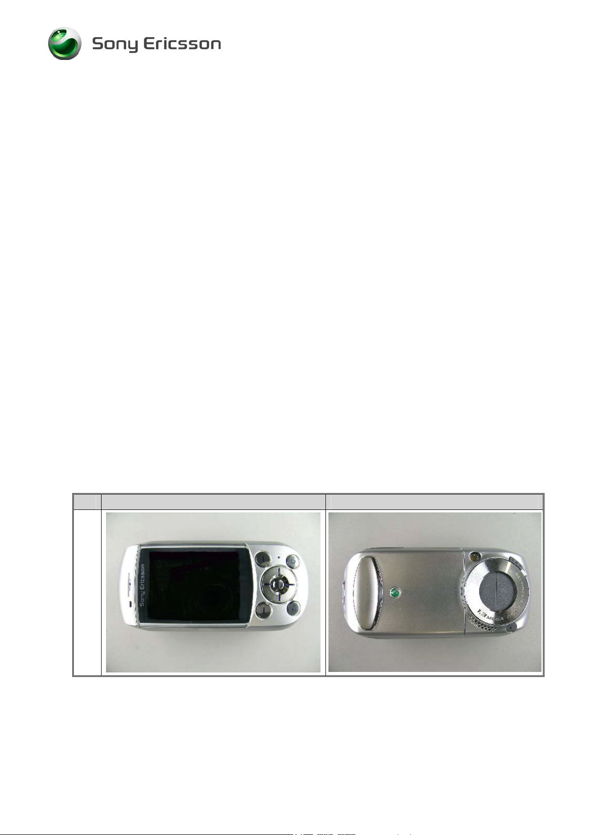
Phone views
Front view Back view
3/00021-1/FEA 209 544/89 B
Company Internal
Sony Ericsson Mobile Communications AB
3(51)
Page 4
Working Instruction, Mechanical
Step-by-Step Instructions
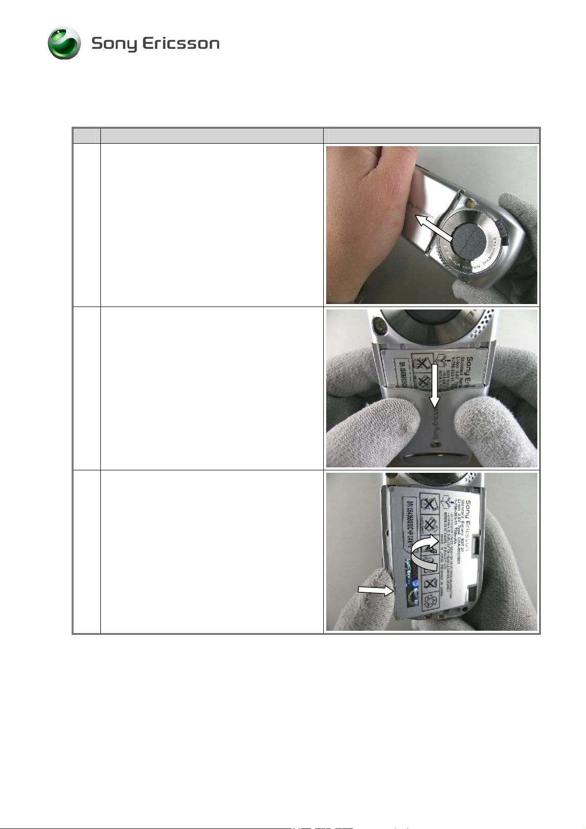
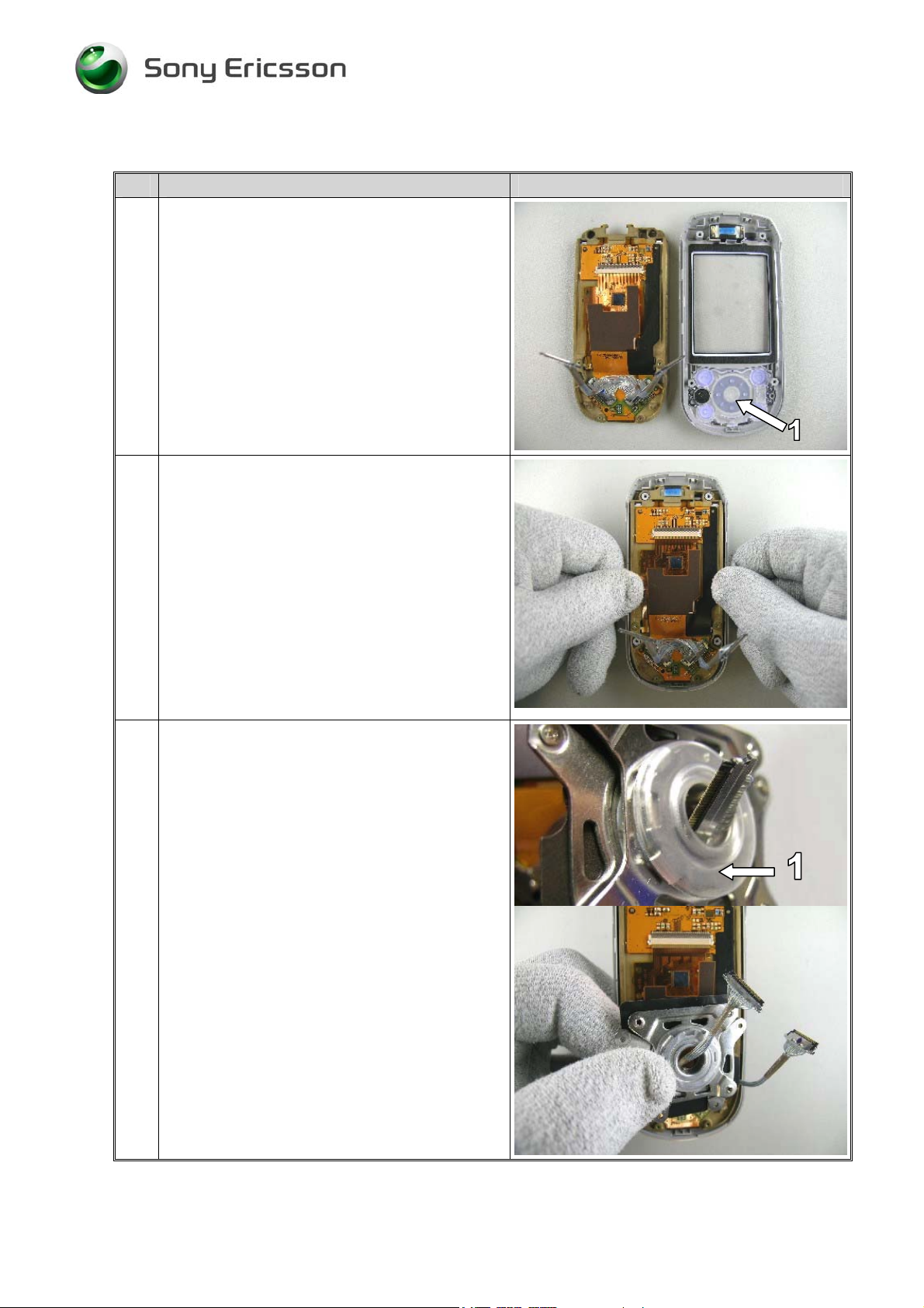
1 NOTE!
Turn off the phone.
If there is a memory stick duo inside the
phone – Please remove the MS before you
start to disassemble.
Remove the battery cover with your hand. Force
the battery cover to slide from its mounted
position towards the end of the phone.
2 Slide down the battery cover completely and
remove it.
3 Remove the battery from the phone with your
fingers. Start like the picture show.
NOTE!
Open out the phone 180º
3/00021-1/FEA 209 544/89 B
Company Internal
Sony Ericsson Mobile Communications AB
4(51)
Page 5
Working Instruction, Mechanical
Step-by-Step Instructions
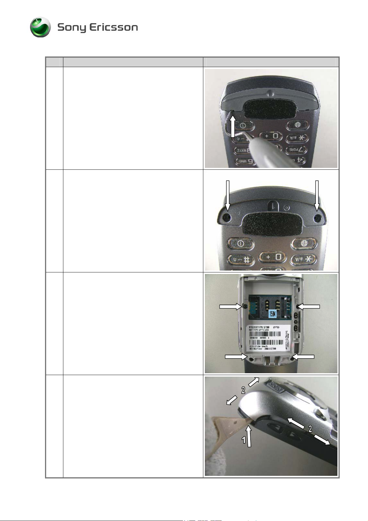
4 NOTE!
Be careful with the dentist hook. It`s easy to
scratch the frame.
Use the dentist hook to gently bend/remove the
panel key front.
NOTE!
If necessary – clean the surface of the panel key
front cavity with Isopropyl alcohol.
5 Remove the two case key front screws at the
bottom of the phone.
NOTE!
1.Removed screws cannot be reused and must be
scrapped.
2. Turn the phone around.
6 Remove the four case key rear screws .
NOTE!
Removed screws cannot be reused and must be
scrapped.
7 NOTE!
Be careful not to scratch the phone with the
opening tool.
Open the phone with the front opening tool
Begin as the picture shows (1).
Then gently move the tool along the gap both
ways until the case key rear is loose on all sides
(2).
If necessary do the same thing on the other side.
3/00021-1/FEA 209 544/89 B
Company Internal
Sony Ericsson Mobile Communications AB
5(51)
Page 6
Working Instruction, Mechanical
Step-by-Step Instructions
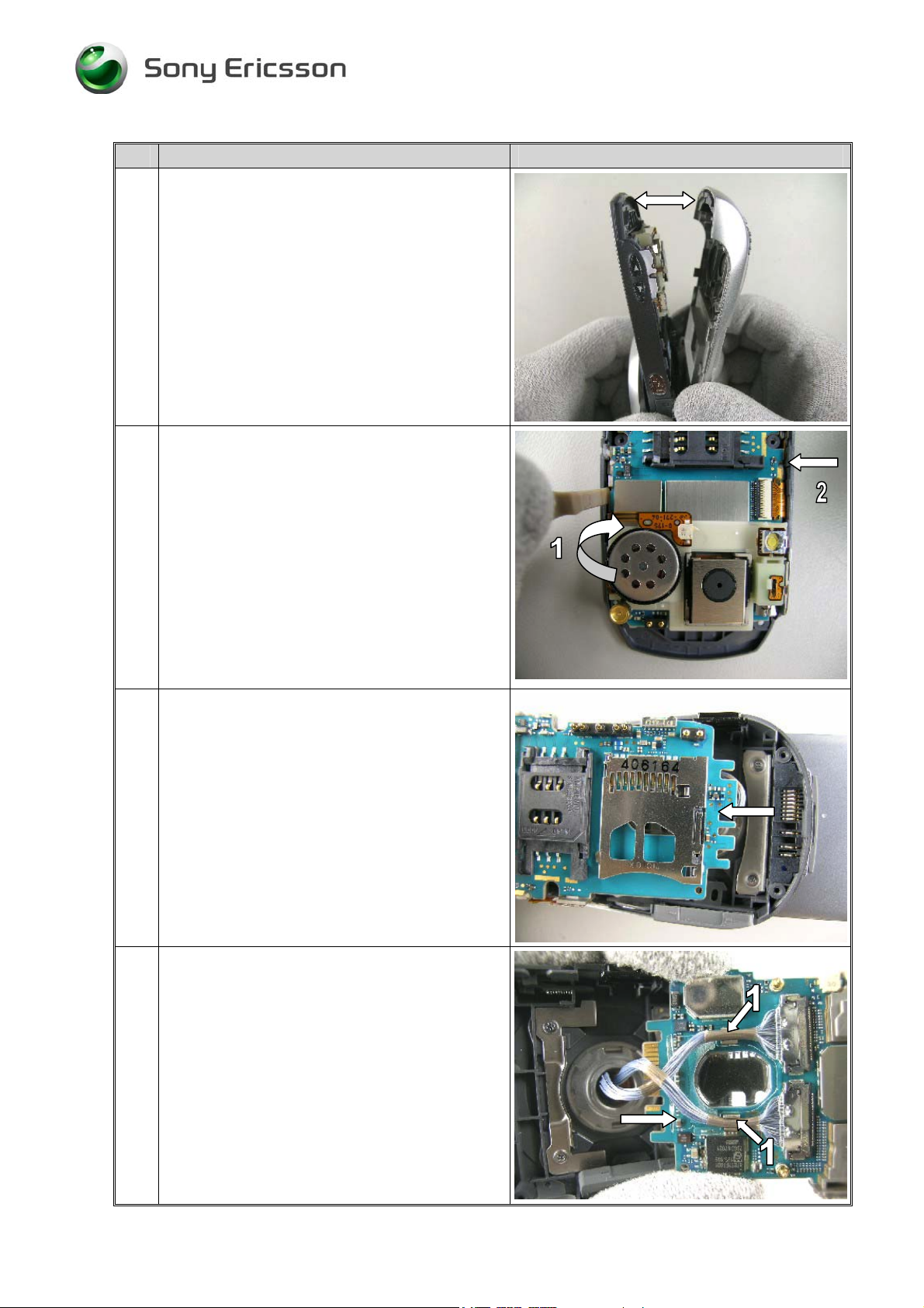
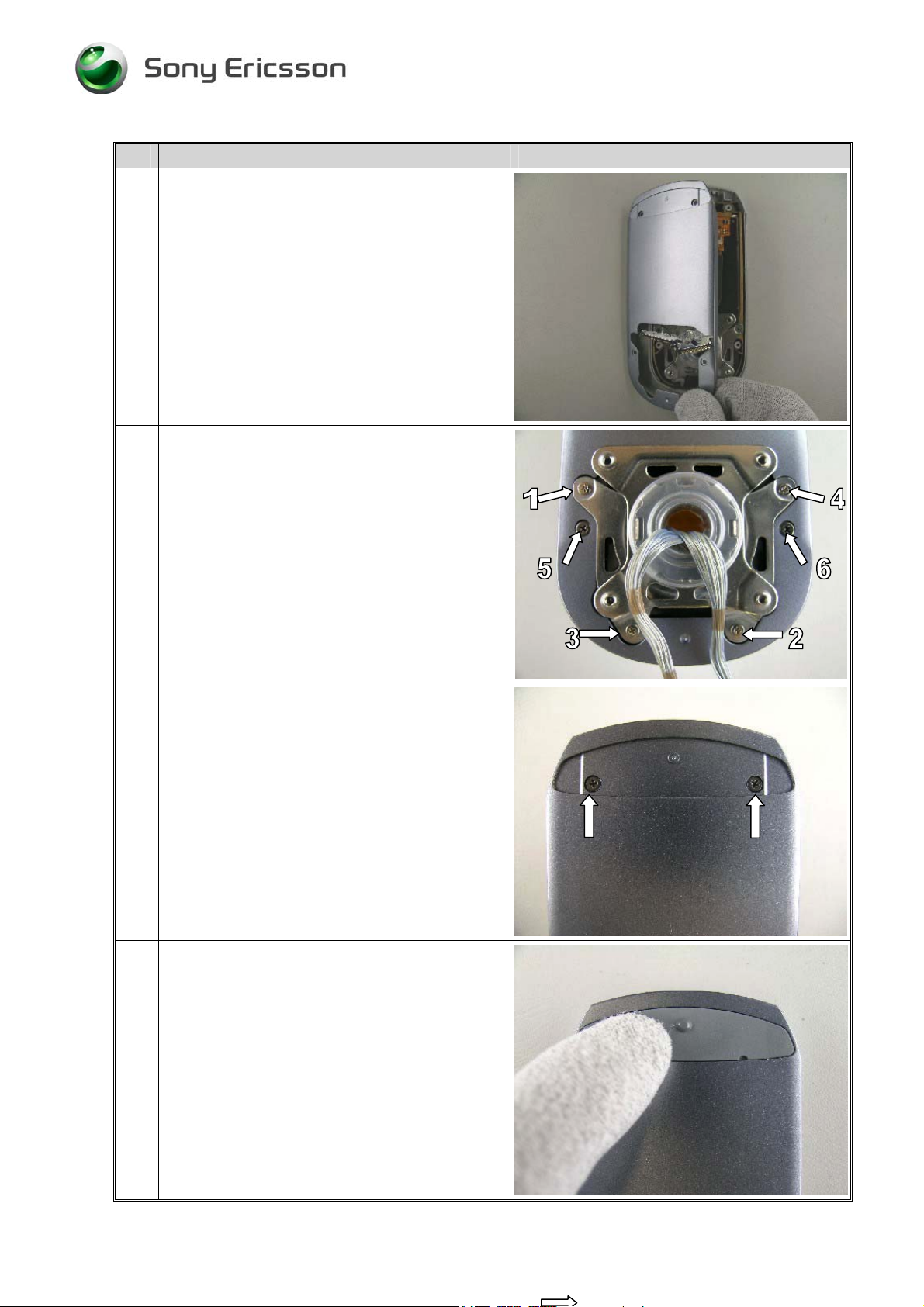
8 Open the lower cabinet cautiously.
9 NOTE!
Be careful not to damage the circuit board with
the opening tool.
With the front opening tool, release catches that
hols the main PBA in the case key front. Start
like the picture show (1).
If necessary do the same thing on the other side
(2). (make sure to avoid prying on the flex films)
NOTE!
Sometimes it helps if you bend the frame a little
side to side.
10
To remove the main PBA, lift the camera end of
the circuit board away from the case key front as
high as it will easily move.
With the PBA in the lifted position, wiggle the
board back and forth while pulling the board
away from the system connector.
NOTE!
Don’t bend the circuit board to much upwards.
11 NOTE!
Always be careful with the “two main cables”
(Harness) (1).
Open out the main PBA from the frame
NOTE! VERY IMPORTANT!
Remember how the two main cables (Harness)
are assembled “with a twist/crossover” to the
main PBA
3/00021-1/FEA 209 544/89 B
Company Internal
Sony Ericsson Mobile Communications AB
6(51)
Page 7
Working Instruction, Mechanical
Step-by-Step Instructions
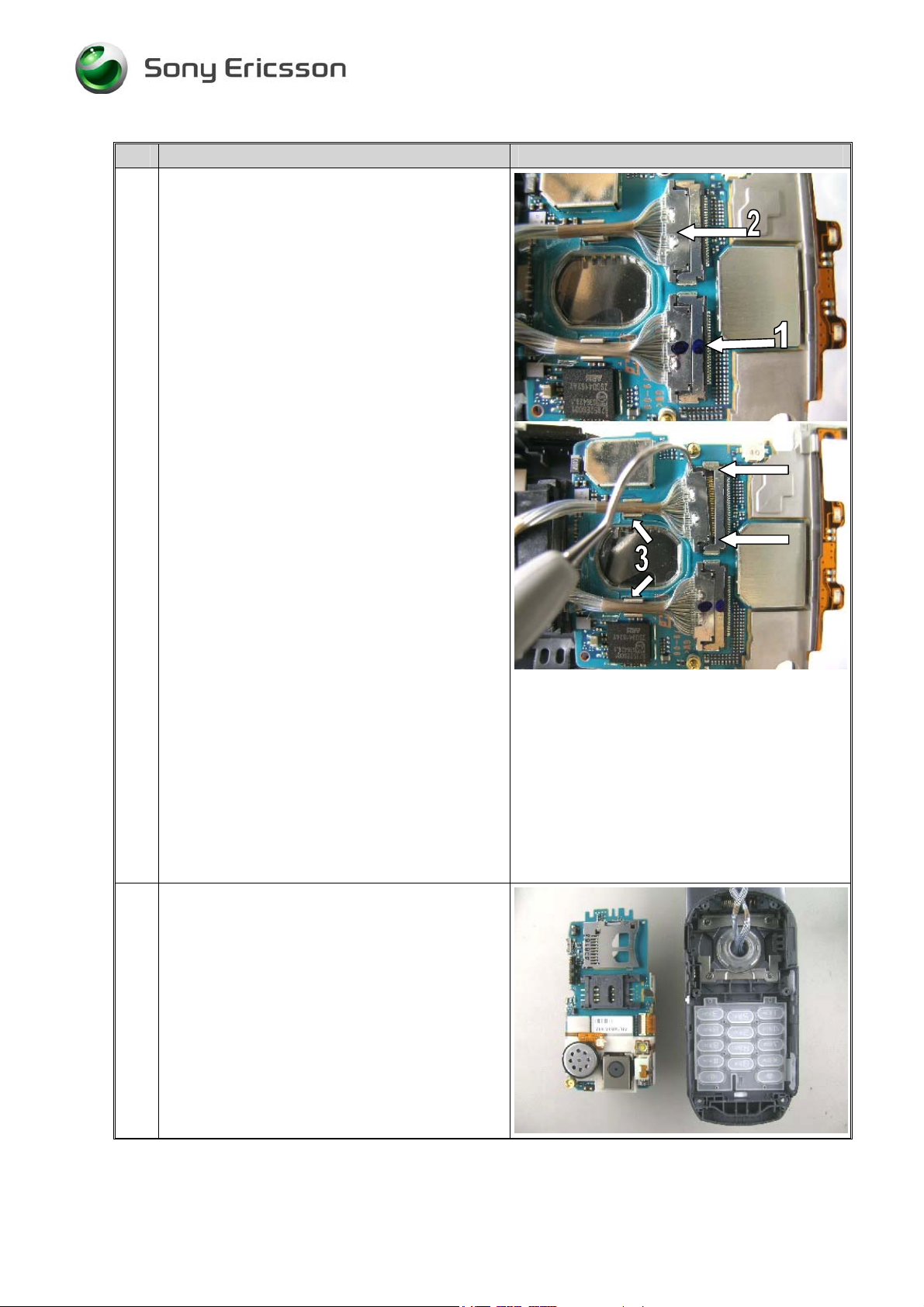
12 Mark one of the contacts with a colour marker
(1). Otherwise it’s easy to mix up the cables
when reassembling the phone.
NOTE!
Notice the two small “knobs” (2) on the UPPER
side on the connector – they must be directed
like the pictures shows when they are
reassembled.
NOTE!
Remove the two cables from their clips (3).
NOTE!
Be careful not to damage the two cable
connections when unplugging the connections
using the dentist hook.
NOTE!
Do not pull on the mass of cables that make up
the cable assembly.
At one of the cable/board connections, use the
dentist hook to unplug the cable connection from
the board. There are two locations that the
connector must be alternately pulled at to free
the cable from its mating board connector. The
location at the two parallel arrows, are the
two pulling locations. The cable should be
pulled towards the end of the circuit board in
which the system connector mounts.
Remove both connectors.
13
Case key rear and circuit board
disassembled.
3/00021-1/FEA 209 544/89 B
Company Internal
Sony Ericsson Mobile Communications AB
7(51)
Page 8
Working Instruction, Mechanical
Step-by-Step Instructions
14 Sometimes the camera button (1) and the light
guide (2) falls out after the main PBA is
removed. If necessary remove the button and the
light guide with a blunt pair of tweezers.
.
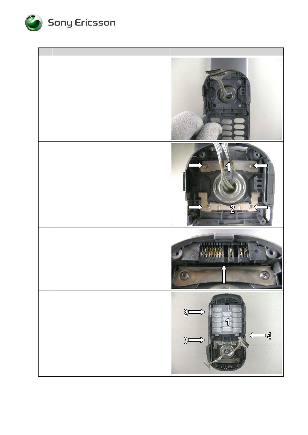
15 Remove the button key by hand or with a blunt
pair of tweezers.
16 NOTE!
Be careful with the dentist hook. It`s easy to
scratch the frame.
Use the dentist hook to gently bend/remove the
panel LCD rear from the case LCD rear.
17 Remove the two case LCD rear screws at the
bottom of the phone.
NOTE!
Removed screws cannot be reused and must be
scrapped.
3/00021-1/FEA 209 544/89 B
Company Internal
Sony Ericsson Mobile Communications AB
8(51)
Page 9
Working Instruction, Mechanical
Step-by-Step Instructions
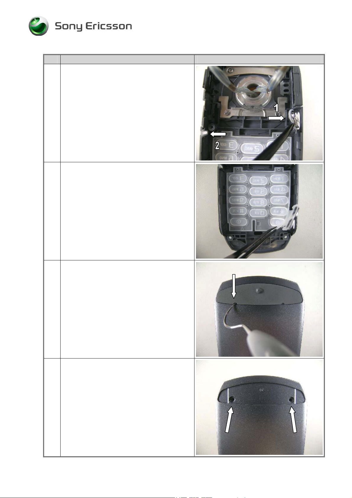
18 Remove the four hinge frame screws at the
bottom of the case key front.
NOTE!
Keep track of the different sizes of screws used
inside the phone.
NOTE!
The four removed screws cannot be reused.
19 Remove the upper (1) and lower (2) hinge frame
holdings with the flex film assembly tool.
20 NOTE!
Be careful not to damage the two cable
assemblies when removing the inner half of the
case key front.
Remove the case key front.
21 Remove the four hinge screws (1), then the two
case LCD rear screws (2).
NOTE!
Keep track of the different sizes of the screws.
Removed screws cannot be reused and must be
scrapped.
3/00021-1/FEA 209 544/89 B
Company Internal
Sony Ericsson Mobile Communications AB
9(51)
Page 10
Working Instruction, Mechanical
Step-by-Step Instructions
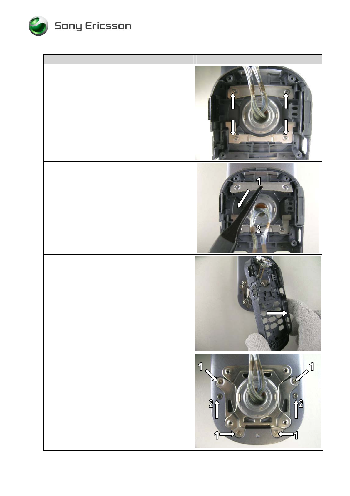
22 NOTE!
Be careful not to damage the two main cables
when folding them.
Lift the hinge assembly from the display case
and work the end of each cable assembly one at
a time through the hole in the hinge assembly.
(1).
The Bush Hinge , transparent, (2) may fall off
from the hingemechanism – put it back on the
hinge-mechanism so you can keep a track on it.
23 NOTE!
Be careful not to scratch the phone with the
opening tool.
Open the LCD case with the opening tool. Begin
like the pictures show (1).
Then gently move the tool along the gap both
ways until the front is loose on all sides (2).
If necessary do the same thing on the other side.
24 NOTE!
Be careful not to damage the case key front and
the case LCD rear.
Open the upper cabinet with caution.
Remove the case LCD front from the case LCD
rear (1).
3/00021-1/FEA 209 544/89 B
Company Internal
Sony Ericsson Mobile Communications AB
10(51)
Page 11

Working Instruction, Mechanical
Step-by-Step Instructions
25 NOTE!
1. Be careful not to damage the LCD unit with
the opening tool.
2. When handling the main LCD be careful and
do not ever touch the display glass.
With the front opening tool, gently release the
display carrier from the Case key front. If
necessary do the same thing on the other side.
NOTE!
Sometimes it helps if you bend the frame a little
side to side.
26 Remove the the LCD unit (with the frame) from
the case key front.
27
Case LCD front and LCD unit disassembled.
3/00021-1/FEA 209 544/89 B
Company Internal
Sony Ericsson Mobile Communications AB
11(51)
Page 12

Working Instruction, Mechanical
2 Reassembly
Tools
• Torque screwdriver, set to 9, 14, 17 and 20 Ncm ± 6%. Bits NTZ 112 1052
• Flex film assembly tool NTZ 112 521
• Blunt pair of tweezers, pair of tweezers
• Front opening tool NTZ 112 302/2
• Dentist hook
Equipment
• ESD-gloves (cotton gloves)
• ESD-wristband
Instruction
Keep all contact surfaces clean of dirt and hand-grease
3/00021-1/FEA 209 544/89 B
Company Internal
Sony Ericsson Mobile Communications AB
12(51)
Page 13
Working Instruction, Mechanical
Step-by-Step Instructions
1 Start like this when reassembling the upper
cabinet.
NOTE!
Make sure that all of the LCD buttons (1) are
correctly assembled.
2 NOTE!
Make sure that the front glas is clean.
Use air blow equipment if necessary.
Place the LCD unit in the case LCD front by
hand
NOTE!
If you are going to assemble a new front:
Don`t forget to remove the protection foil
inside the front, with a pair of tweezers. Be
careful not to scratch the glass with the
tweezers.
3 NOTE!
Be careful not to damage the two main cables
when sliding them through the hinge
mechanism.
NOTE!
Don’t forget the bush hinge (1)
Gently fold each end of the cables until they can
slide through the center hole of the
hingemechanism.
3/00021-1/FEA 209 544/89 B
Company Internal
Sony Ericsson Mobile Communications AB
13(51)
Page 14
Working Instruction, Mechanical
Step-by-Step Instructions
4 Slide on the case LCD rear over the cables,
hinge and on to the case LCD front and snap
them together.
NOTE!
Check so the lower cabinet is properly
assembled – there should be no gaps along the
sides.
5 NOTE!
Use 9 Ncm of torque for the LCD hinge screws
(1, 2, 3, and 4).
Use 17 Ncm of torque for the LCD cabinet
screws (5, 6).
Assemble six new screws. Tighten the upper
cabinet screws according to screw sequence
shown in the picture.
6 NOTE!
Use 17 Ncm of torque for the screws.
Assemble two new screws in the case LCD rear
cavity.
7 NOTE!
If necessary – clean the surface of the panel
LCD rear cavity with Isopropyl alcohol.
Assemble the panel LCD rear (comes with a
new adhesive) with your fingers.
Upper cabinet resassembled.
3/00021-1/FEA 209 544/89 B
Company Internal
Sony Ericsson Mobile Communications AB
14(51)
Page 15
Working Instruction, Mechanical
Step-by-Step Instructions
8 NOTE!
Be careful not to damage the two cables.
Slide both cables through the hole in the case
key front.
9 NOTE!
Use 14 Ncm of torque for the key hinge screws.
Assemble the two upper (1) and lower (2) hinge
frame holdings together with four new screws
10 NOTE!
If you have assembled a new case key front
doesn’t forget to assemble a new system
connector.
The picture shows a correctly mounted system
connector.
11
NOTE!
Close the phone together 180º.
If necessary, place a new keyboard inside the
case key front by hand (1).
NOTE!
Make sure that the keyboard (1), volume keys
(2), kamera key (3) and the light guide (4) are
assembled and in the right position.
3/00021-1/FEA 209 544/89 B
Company Internal
Sony Ericsson Mobile Communications AB
15(51)
Page 16
Working Instruction, Mechanical
Step-by-Step Instructions
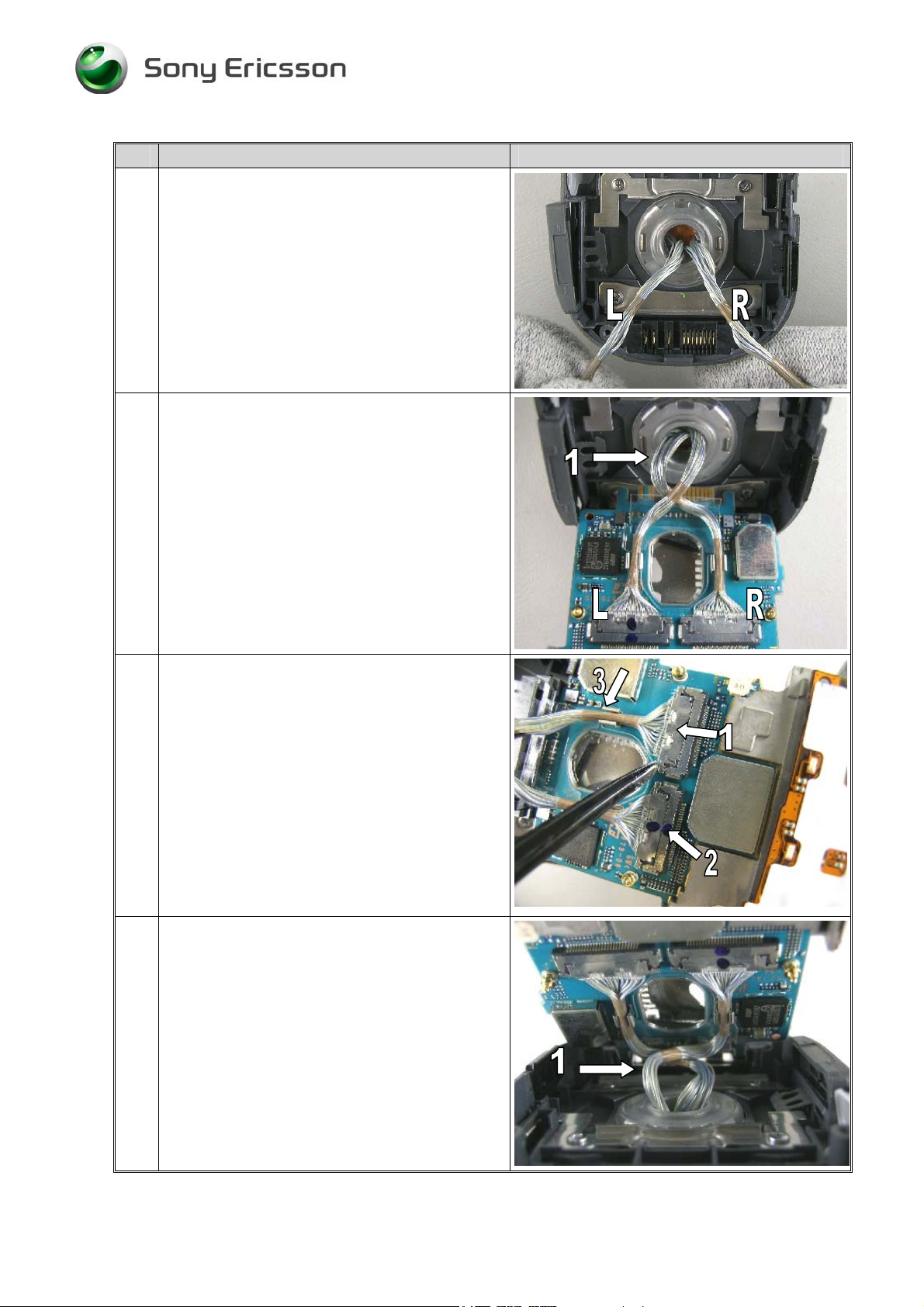
12 NOTE!
When reassembling the two main cables
(harness) to the main PBA start like the picture
shows.
The left cable (L) should go to the left connector
on the PBA (See picture 13).
The right cable (R) should go to the right
connector on the PBA (See picture 13).
13 Place the main PBA against the case key front
like the picture shows; start to connect the two
cables to respectively left and right ZIF
connector.
Take notice of the “crossover” (1).
14 NOTE!
1. Be careful not to damage the two main cables
and the connectors with the tweezers.
2. Notice on the two small “knobs” (1) on the
UPPER side on the connector – they must be
directed like the pictures shows when they are
reassembled.
Assemble the two main cables with a blunt pair
of tweezers. Use your markings so they don’t get
mixed up (2).
Gently assemble the two cables in their clips (3).
15 NOTE!
After reassembling of the two ZIF-connectors it
should look like this “with a crossover” (1)
before you completely fold down the main PBA
towards the case key front.
Then carefully fold the main PBA over towards
the case key front and start to slide it into the
system connector.
3/00021-1/FEA 209 544/89 B
Company Internal
Sony Ericsson Mobile Communications AB
16(51)
Page 17

Working Instruction, Mechanical
Step-by-Step Instructions
16 NOTE!
Before you slide the main PBA to the bottom of
the system connector, check all flexfilm
connections, key buttons and the two main
cables are folded correctly so nothing get
squeezed or damaged between the PBA and the
case key front frame.
Slide the main PBA into the system connector.
17 Place the main PBA completely into the case
key front.
Press gently on the PBA edges with your hand
(by the arrows).
NOTE!
Make sure that the main PBA is mounted
correctly in the case key front.
18
NOTE!
Open out the phone 180º.
Assemble the case key rear over the case key
front and gently snap them together.
NOTE!
Check so the lower cabinet is properly
assembled – there should be no gaps along the
sides.
19 NOTE!
Use 20 Ncm of torque for the case key rear
screws.
Assemble four new screws. Tighten the case key
rear screws according to screw sequence shown
in the picture.
Turn the phone around.
3/00021-1/FEA 209 544/89 B
Company Internal
Sony Ericsson Mobile Communications AB
17(51)
Page 18

Working Instruction, Mechanical
Step-by-Step Instructions
20 NOTE!
Use 20 Ncm of torque for the case key front
screws.
Assemble two new screws in the case key front
cavity.
21 NOTE!
If necessary – clean the surface of the case key
front cavity with Isopropyl alcohol.
Assemble the panel key front (comes with a new
adhesive) with your fingers.
22 Place the battery like the picture show.
23 Slide on the battery cover like the picture show.
3/00021-1/FEA 209 544/89 B
Company Internal
Sony Ericsson Mobile Communications AB
18(51)
Page 19

Working Instruction, Mechanical
Step-by-Step Instructions
24
Upper and lower cabinet unit reassembled.
3/00021-1/FEA 209 544/89 B
Company Internal
Sony Ericsson Mobile Communications AB
19(51)
Page 20

Working Instruction, Mechanical
3 Replacement of Mechanical Parts
Equipment
• ESD-gloves (cotton gloves)
• ESD-wristband
• Dentist hook
• Slot screwdriver
• Blunt pair of tweezers
• Flex film assembly tool NTZ 112 521
• Front opening tool NTZ 112 302/2
• Torque screwdriver, set to 9, 14, 17 and 20 Ncm ± 6%. Bits NTZ 112 1052
Instruction
• Keep all contact surfaces clean of dirt and hand-grease
3.1 Case key rear
Replacement of case key rear: Check Disassembly and Reassembly headings and draw
attention to the Note comments.
3.2 Case key front
Replacement of case key front: Check Disassembly and Reassembly headings and draw
attention to the Note comments.
3.3 Case LCD front
Replacement of the case LCD front: Check Disassembly and Reassembly headings and
draw attention to the Note comments.
3/00021-1/FEA 209 544/89 B
Company Internal
Sony Ericsson Mobile Communications AB
20(51)
Page 21

Working Instruction, Mechanical
3.4 Case LCD rear
Replacement of the case LCD rear: Check Disassembly and Reassembly headings and
draw attention to the Note comments.
3.5 Hinge and Bush hinge
Replacement of the hinge and bush hinge: Check Disassembly and Reassembly headings
and draw attention to the Note comments.
3.6 Harness (Main cables)
Replacement of the harness (main cables): Check Disassembly and Reassembly headings
and draw attention to the Note comments.
3.7 Battery cover assembly
Replacement of the battery cover assembly: Check Disassembly and Reassembly
headings and draw attention to the Note comment.
3.8 Panel key front
Replacement of the panel key front: Check Disassembly and Reassembly headings and
draw attention to the Note comment.
3.9 Panel LCD rear
Replacement of the panel LCD rear: Check Disassembly and Reassembly headings and
draw attention to the Note comment.
3/00021-1/FEA 209 544/89 B
Company Internal
Sony Ericsson Mobile Communications AB
21(51)
Page 22

Working Instruction, Mechanical
3.10 Adhesives
NOTE!
If necessary – clean the surface where the adhesive was assembled with Isopropyl alcohol.
Replacement of all the Adhesives. Use a dentist hook or a blunt pair of tweezers to
remove the old used adhesive and replace it with a new one.
3.11 Cover RF
Step-by-Step Instructions
1 Remove the external antenna plug with the
dentist hook.
Assemble a new external antenna plug with your
fingers.
3/00021-1/FEA 209 544/89 B
Company Internal
Sony Ericsson Mobile Communications AB
22(51)
Page 23

Working Instruction, Mechanical
3.12 Sheet absorption A
• Disassemble the phone as described in 1 Disassembly.
Step-by-Step Instructions
1 Remove the sheet absorption A with a blunt pair
of tweezers.
Assemble a new sheet absorption A with the
tweezers.
• Assemble the phone as described in 2 Reassembly.
3.13 Cover system connector I/O
Step-by-Step Instructions
1 Remove the cover system connector I/O with
your fingers.
Assemble a new cover by hand.
3/00021-1/FEA 209 544/89 B
Company Internal
Sony Ericsson Mobile Communications AB
23(51)
Page 24

Working Instruction, Mechanical
3.14 Cover MS
Step-by-Step Instructions
1 Remove the cover MS with your fingers.
Assemble a new cover by hand.
3.15 Button lock switch assy
• Disassemble the phone as described in 1 Disassembly.
Step-by-Step Instructions
1 NOTE!
Be careful with the spring (1).
Remove the button lock switch assy with a blunt
pair of tweezers (2).
Assemble a new button lock switch assy with
your fingers and with the tweezers.
• Assemble the phone as described in 2 Reassembly.
3/00021-1/FEA 209 544/89 B
Company Internal
Sony Ericsson Mobile Communications AB
24(51)
Page 25

Working Instruction, Mechanical
3.16 System Connector
• Disassemble the phone as described in 1 Disassembly.
Step-by-Step Instructions
1 Slide the main PBA backwards from the system
connector with your fingers.
NOTE!
Don’t bend the PBA to much upwards.
2 NOTE!
Sometimes it needs quite a lot of force until the
system connector become loose.
With a slot screwdriver gently bend against the
hinge frame holding (under the system
connector) until the system connector become
loose.
3 Remove the old system connector with a blunt
pair of tweezers.
Assemble a new system connector with your
fingers.
NOTE!
Press the system connector firmly to the bottom
of the case key front cavity.
4 Correctly mounted system connector.
NOTE!
Don’t forget to reassemble the cover system
connector I/O (3.13).
• Assemble the phone as described in 2 Reassembly.
3/00021-1/FEA 209 544/89 B
Company Internal
Sony Ericsson Mobile Communications AB
25(51)
Page 26

Working Instruction, Mechanical
3.17 Cushion LCD hinge
• Disassemble the phone as described in 1 Disassembly.
Step-by-Step Instructions
1 Remove the cushion LCD hinge by hand or with
a blunt pair of tweezers.
2 NOTE!
1. If necessary – clean the surface of the cushion
LCD hinge with Isopropyl alcohol.
2. The cushion LCD hinge should be aligned
like the picture shows.
Assemble a new cushion LCD hinge with your
fingers or with the tweezers.
• Assemble the phone as described in 2 Reassembly.
3/00021-1/FEA 209 544/89 B
Company Internal
Sony Ericsson Mobile Communications AB
26(51)
Page 27

Working Instruction, Mechanical
3.18 LCD unit
• Disassemble the phone as described in 1 Disassembly.
Step-by-Step Instructions
1
NOTE!
Be very careful not to damage the FPC
connector clamp when closing it. The clamp
may fall off and then the connector must be
replaced (electrical repair).
Open the FPC connector with the
flex film assembly tool.
2 NOTE!
Do not touch the display glass with your fingers.
Gently fold the LCD forward by hand.
3 NOTE!
Be careful with the LCD flexfilm.
Slide the LCD screen and the flexfilm through
and away from the LCD frame.
Assemble a new LCD unit in the reverse
direction.
NOTE!
Don`t forget to remove the protection foil. Be
careful not to scratch the glass.
• Assemble the phone as described in 2 Reassembly.
3/00021-1/FEA 209 544/89 B
Company Internal
Sony Ericsson Mobile Communications AB
27(51)
Page 28

Working Instruction, Mechanical
3.19 Cushion frame LCD
• Disassemble the phone as described in 1 Disassembly.
Step-by-Step Instructions
1 NOTE!
1. If necessary – clean the surface of the frame
LCD with Isopropyl alcohol.
2. The cushion frame LCD should be assembled
like the picture shows.
Remove the old cushion frame LCD with a blunt
pair of tweezers.
Assemble a new one with with the tweezers.
• Assemble the phone as described in 2 Reassembly.
3/00021-1/FEA 209 544/89 B
Company Internal
Sony Ericsson Mobile Communications AB
28(51)
Page 29

Working Instruction, Mechanical
3.20 FPC hinge
• Disassemble the phone as described in 1 Disassembly.
Step-by-Step Instructions
1 NOTE!
1. Notice how the FPC hinge is assembled
before you remove it.
2. Be careful with the tweezers.
Gently bend with a blunt pair of tweezers under
the FPC hinge until it become loose.
2 Turn the LCD frame around and do the same
thing again on the other side.
3 NOTE!
If necessary, clean the surface of the frame with
Isopropyl alcohol before you assemble new
adhesives.
The picture shows the FPC hinge separated from
the LCD unit frame.
Assemble a new FPC hinge in the reverse
direction.
• Assemble the phone as described in 2 Reassembly.
3/00021-1/FEA 209 544/89 B
Company Internal
Sony Ericsson Mobile Communications AB
29(51)
Page 30

Working Instruction, Mechanical
3.21 LCD flex sheet key
• Disassemble the phone as described in 1 Disassembly.
Step-by-Step Instructions
1 Remove the old LCD flex sheet key with a blunt
pair of tweezers (1) and with your hands.
NOTE!
1. If necessary – clean the surface of the FPC
hinge with Isopropyl alcohol.
2. The LCD flex sheet key should be aligned to
the three holes on the FPC hinge (2).
Assemble a new one with your fingers or with
the tweezers.
• Assemble the phone as described in 2 Reassembly.
3.22 Frame LCD
• Disassemble the phone as described in 1 Disassembly.
Step-by-Step Instructions
1 NOTE!
1. Remove the LCD unit (3.18) and the FPC
hinge (3.20) first.
Replace the old LCD frame with a new one.
NOTE!
Don’t forget to assemble a new Cushion frame
LCD (3.19) and all the adhesives.
• Assemble the phone as described in 2 Reassembly.
3/00021-1/FEA 209 544/89 B
Company Internal
Sony Ericsson Mobile Communications AB
30(51)
Page 31

Working Instruction, Mechanical
3.23 Frame RF
• Disassemble the phone as described in 1 Disassembly.
Step-by-Step Instructions
1 NOTE!
Be careful with the tweezers.
Remove the speaker (1), flex shutter (2), flex
up/down (3) and flex p/light (4) with a blunt pair
of tweezers.
2 NOTE!
Be very careful with the FPC key (Flexfilm).and
the three hooks – they are very fragile.
Gently bend the three RF frame hooks away
from the main PBA with your fingers until the
RF frame became loose.
3 Lift away the old RF frame and replace it with a
new one.
NOTE!
If necessary, clean the surface with Isopropyl
alcohol before you assemble new adhesives.
• Assemble the phone as described in 2 Reassembly.
3/00021-1/FEA 209 544/89 B
Company Internal
Sony Ericsson Mobile Communications AB
31(51)
Page 32

Working Instruction, Mechanical
3.24 Vibrator
• Disassemble the phone as described in 1 Disassembly.
Step-by-Step Instructions
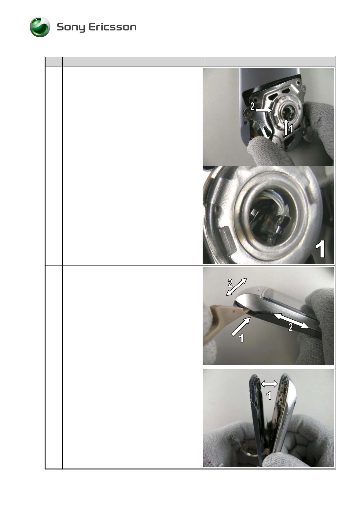
1 NOTE!
1. Remove the Frame RF (3.23) first.
Push the vibrator out from the RF frame with a
blunt pair of tweezers
2 NOTE!
Do not touch the vibrator contact springs or
damage the flywheel.
Lift up the vibrator motor with the tweezers like
the picture shows.
Assemble a new vibrator in the reverse
direction.
NOTE!
Press the vibrator to the bottom of the cavity
gently with a blunt pair of tweezers.
• Assemble the phone as described in 2 Reassembly.
3/00021-1/FEA 209 544/89 B
Company Internal
Sony Ericsson Mobile Communications AB
32(51)
Page 33

Working Instruction, Mechanical
3.25 Key FPC
• Disassemble the phone as described in 1 Disassembly.
Step-by-Step Instructions
1
NOTE!
Remove all the FPC key equipment connected
by a adhesive with a blunt pair of tweezers like
the pictures shows.
Be very careful not to damage the FPC
connector clamp when closing it. The clamp
may fall off and then the connector must be
replaced (electrical repair).
Open the FPC connector with the
flex film assembly tool and remove the flexfilm
from the connector.
2 The FPC key is held in place to the frame BB
with three hooks (by the arrows)
3 Gently remove the old FPC key with a blunt pair
of tweezers and with your hands like the picture
shows.
3/00021-1/FEA 209 544/89 B
Company Internal
Sony Ericsson Mobile Communications AB
33(51)
Page 34

Working Instruction, Mechanical
Step-by-Step Instructions
4 NOTE!
The key FPC should be aligned to the frame BB
by the two guide pins (1) and to the three hooks
(2).
Assemble a new key FPC in the reverse
direction.
• Assemble the phone as described in 2 Reassembly.
3.26 Frame BB
• Disassemble the phone as described in 1 Disassembly
Step-by-Step Instructions
1 NOTE!
1. Remove the Frame RF (3.23) and the Key
FPC (3.25) first.
2. Be careful with the camera assembly
3. Be very careful with the four little hooks.
Remove the frame. It`s attatched to the PBA
with four small hooks on the edges (1).
Just bend with your hand until the frame become
loose.
• Assemble the phone as described in 2 Reassembly.
3/00021-1/FEA 209 544/89 B
Company Internal
Sony Ericsson Mobile Communications AB
34(51)
Page 35

Working Instruction, Mechanical
3.27 Spring, A
• Disassemble the phone as described in 1 Disassembly.
Step-by-Step Instructions
1 NOTE!
Remove the Frame RF (3.23), Key FPC (3.25)
and the Frame BB (3.26) first.
Replace the old Spring, A with new ones, use a
blunt pair of tweezers.
• Assemble the phone as described in 2 Reassembly.
3/00021-1/FEA 209 544/89 B
Company Internal
Sony Ericsson Mobile Communications AB
35(51)
Page 36

Working Instruction, Mechanical
3.28 Key flex sheet key (Domes)
• Disassemble the phone as described in 1 Disassembly.
Step-by-Step Instructions
1 Remove the old key flex sheet key with a blunt
pair of tweezers.
NOTE!
1. If necessary – clean the surface of the key
FPC with Isopropyl alcohol.
2. The Key flex sheet key should be aligned to
the markings and the holes on the key FPC.
Assemble a new one with your fingers or with
the tweezers.
• Assemble the phone as described in 2 Reassembly.
3.29 Operator badge
Step-by-Step Instructions
1 NOTE!
Be careful not to scratch the front with the
dentist hook.
If necessary – clean the surface of the cobranded cavity with Isopropyl alcohol.
Gently remove the old brand badge with a
dentist hook like the picture shows.
Assemble a new brand badge with a blunt pair of
tweezers.
3/00021-1/FEA 209 544/89 B
Company Internal
Sony Ericsson Mobile Communications AB
36(51)
Page 37

Working Instruction, Mechanical
3.30 Receiver
• Disassemble the phone as described in 1 Disassembly.
Step-by-Step Instructions
1 NOTE!
1. Be careful with the tweezers.
2. Do not touch or damage the dual receiver
contact springs with your fingers or with the
assembly tools.
Remove the old receiver with a blunt pair of
tweezers.
Place a new receiver into the frame cavity. Press
gently on the receiver with the tweezers to
secure a good fit.
NOTE!
Press the receiver to the bottom of the cavity.
• Assemble the phone as described in 2 Reassembly.
3.31 Microphone
• Disassemble the phone as described in 1 Disassembly.
Step-by-Step Instructions
1 Remove the old microphone with a dentist hook.
NOTE!
1. Do not press in the center of the microphone
(damage may occur).
2. Do not touch or damage the dual microphone
contact springs with your fingers or with the
assembly tools.
Place a new microphone into the frame cavity.
Press gently on the microphone edges with a
blunt pair of tweezers to secure a good fit.
NOTE!
Press the microphone to the bottom of the
cavity.
• Assemble the phone as described in 2 Reassembly.
3/00021-1/FEA 209 544/89 B
Company Internal
Sony Ericsson Mobile Communications AB
37(51)
Page 38

Working Instruction, Mechanical
3.32 Buttons LCD (Top, Side, Base and Center)
• Disassemble the phone as described in 1 Disassembly.
Step-by-Step Instructions
1 Remove the old LCD base button with a blunt
pair of tweezers.
Assemble a new base button with the tweezers
or by hand.
2 Remove the old LCD side button with a blunt
pair of tweezers.
Assemble a new side button with the tweezers or
by hand.
3 NOTE!
Notice the LCD button position before removal.
Remove the old LCD top button with a blunt
pair of tweezers.
Assemble a new top button by hand or with the
tweezers.
• Assemble the phone as described in 2 Reassembly.
3/00021-1/FEA 209 544/89 B
Company Internal
Sony Ericsson Mobile Communications AB
38(51)
Page 39

Working Instruction, Mechanical
3.33 Button shutter
• Disassemble the phone as described in 1 Disassembly.
Step-by-Step Instructions
1 NOTE!
Remove the main PBA first (See chapter 1.
Disassembly).
Remove the old shutter button with a blunt pair
of tweezers.
Assemble a new one with the tweezers.
2 Use the guide pin (1) when reassembling the
button shutter.
NOTE!
Make sure that the button shutter is assembled in
the right position.
• Assemble the phone as described in 2 Reassembly.
3/00021-1/FEA 209 544/89 B
Company Internal
Sony Ericsson Mobile Communications AB
39(51)
Page 40

Working Instruction, Mechanical
3.34 Light Guide (Charge LED)
• Disassemble the phone as described in 1 Disassembly.
Step-by-Step Instructions
1 NOTE!
Be careful not to scratch the light guide with the
tweezers.
Remove the old light guide with a blunt pair of
tweezers.
Assemble a new one with the tweezers.
• Assemble the phone as described in 2 Reassembly.
3.35 Liquid intrusion indicator
• Disassemble the phone as described in 1 Disassembly.
Step-by-Step Instructions
1 NOTE!
Notice the liquid intrusion indicator position on
the phone.
If necessary clean the frame surface with
Isopropyl alcohol before you assemble the new
indicator.
Remove the old liquid intrusion indicator and
replace it with a new one.
• Assemble the phone as described in 2 Reassembly.
3/00021-1/FEA 209 544/89 B
Company Internal
Sony Ericsson Mobile Communications AB
40(51)
Page 41

Working Instruction, Mechanical
3.36 Camera 1,3M CCD (MCX-CC5)
• Disassemble the phone as described in 1 Disassembly
Step-by-Step Instructions
2
NOTE!
Remove the Frame RF (3.23), Key FPC (3.25)
and the Frame BB (3.26) first.
Be very careful not to damage the FPC
connector clamp when opening or closing it.
The clamp may fall off and then the
connector must be replaced (electrical
repair).
Open the FPC connector with the
flex film assembly tool.
3 NOTE!
Be careful with the camera assembly and
flexfilm.
Remove the old camera assembly.
Assemble a new camera assembly, press it to the
bottom of the FPC connector and close it with
the flex film assembly tool.
• Assemble the phone as described in 2 Reassembly.
3/00021-1/FEA 209 544/89 B
Company Internal
Sony Ericsson Mobile Communications AB
41(51)
Page 42

Working Instruction, Mechanical
3.37 Magnet
• Disassemble the phone as described in 1 Disassembly
Step-by-Step Instructions
1 NOTE!
If necessary clean the surface of the LCD rear
case with Isopropyl alcohol before you assemble
a new adhesive.
Remove the old magnet with a dentist hook.
Assemble a new magnet with a blunt pair of
tweezers.
• Assemble the phone as described in 2 Reassembly.
3.38 Panel IRDA
• Disassemble the phone as described in 1 Disassembly
Step-by-Step Instructions
1 NOTE!
Be careful with the tweezers so you don`t
scratch the IRDA panel.
Remove the old IRDA panel with a blunt pair of
tweezers.
Assemble a new one with the tweezers.
• Assemble the phone as described in 2 Reassembly.
3/00021-1/FEA 209 544/89 B
Company Internal
Sony Ericsson Mobile Communications AB
42(51)
Page 43

Working Instruction, Mechanical
3.39 Button key
• Disassemble the phone as described in 1 Disassembly
Step-by-Step Instructions
1 NOTE!
Be careful not to damage the button key with the
tweezers.
Remove the old button key with a blunt pair of
tweezers or by hand.
Assemble a new one by hand.
2 NOTE!
Check so the button key is correctly assembled.
• Assemble the phone as described in 2 Reassembly.
3/00021-1/FEA 209 544/89 B
Company Internal
Sony Ericsson Mobile Communications AB
43(51)
Page 44

Working Instruction, Mechanical
3.40 Panel camera
• Disassemble the phone as described in 1 Disassembly
Step-by-Step Instructions
1 NOTE!
Be careful with the dentist hook. It`s easy to
scratch the frame.
Remove the old panel camera with a dentist
hook.
NOTE!
If necessary clean the surface of the case key
rear with Isopropyl alcohol before you assemble
new adhesives.
2 NOTE!
Notice the tap (1) on the camera panel that
should be inserted into the case key rear.
Assemble a new panel camera by hand.
• Assemble the phone as described in 2 Reassembly.
3/00021-1/FEA 209 544/89 B
Company Internal
Sony Ericsson Mobile Communications AB
44(51)
Page 45

Working Instruction, Mechanical
3.41 Frame camera cover
• Disassemble the phone as described in 1 Disassembly
Step-by-Step Instructions
1 NOTE!
Be careful not to damage the frame camera
cover with the tweezers.
Remove the old frame camera cover with a blunt
pair of tweezers.
Assemble a new one with the tweezers.
• Assemble the phone as described in 2 Reassembly.
3/00021-1/FEA 209 544/89 B
Company Internal
Sony Ericsson Mobile Communications AB
45(51)
Page 46

Working Instruction, Mechanical
3.42 Cover camera R, Cover camera L
• Disassemble the phone as described in 1 Disassembly
Step-by-Step Instructions
1 NOTE!
Notice which is left and right before removal,
they are marked with an L and R on the back of
the plastic.
Remove the camera covers with a blunt pair of
tweezers or by hand.
Assemble new ones with the tweezers or by
hand.
• Assemble the phone as described in 2 Reassembly
3.43 GSM Antenna
• Disassemble the phone as described in 1 Disassembly.
Step-by-Step Instructions
1 NOTE!
Be very careful with the antenna screw and
don’t over tighten.
Remove the old GSM antenna with a
screwdriver and with your fingers.
Assemble a new antenna and screw.
• Assemble the phone as described in 2 Reassembly.
3/00021-1/FEA 209 544/89 B
Company Internal
Sony Ericsson Mobile Communications AB
46(51)
Page 47

Working Instruction, Mechanical
3.44 BT Antenna
• Disassemble the phone as described in 1 Disassembly.
Step-by-Step Instructions
1 NOTE!
Notice the BT antenna position on the picture.
Remove the old BT antenna with a dentist hook.
Assemble a new antenna with a blunt pair of
tweezers.
• Assemble the phone as described in 2 Reassembly.
3/00021-1/FEA 209 544/89 B
Company Internal
Sony Ericsson Mobile Communications AB
47(51)
Page 48

Working Instruction, Mechanical
4 Label
Tools
• Hot air flow solder station
• Blunt pair of tweezers
• Zebra printer and computer
Instruction
This instruction should be used when you are intending to exchange an old label or assemble
a new one.
NOTE!
Notice the position of the label before removal.
Only one label is allowed on the frame.
1. Read the old label and/or write the information into the Labelmake program.
2. Heat up the label with a hot air flow solder station, if needed.
3. Carefully remove the label, make sure that all residues are gone. If necessary clean the
surface with Isopropyl alcohol. Do not scratch the frame.
4. Check that the right label format is loaded in the Zebra printer.
5. Write a new label by using the program Labelmake. Check that the printing is ok.
6. Take the new label and place it onto the frame according to Fig 1. Make sure that the
label is placed in the right position.
Fig 1.
3/00021-1/FEA 209 544/89 B
Company Internal
Sony Ericsson Mobile Communications AB
48(51)
Page 49

Working Instruction, Mechanical
5 Dummy Battery Cover
Tools
• Color marker
• Pair of scissors
• Side cutter
Instruction
Step-by-Step Instructions
1 Take a new battery cover.
2 Turn the battery cover around.
Mark with some color were you gonna cut the
opening.
3 Cut the opening, for the dummy battery cables
with the sissors (white lines).
3/00021-1/FEA 209 544/89 B
Company Internal
Sony Ericsson Mobile Communications AB
49(51)
Page 50

Working Instruction, Mechanical
Step-by-Step Instructions
4 Bend the part like the picture shows.
NOTE!
Bend as the picture shows, so that the edge
doesn´t damage the dummy battery cables.
5 Cut off the part like the picture shows.
6 Dummy battery cover ready.
7 Dummy battery cover in use.
3/00021-1/FEA 209 544/89 B
Company Internal
Sony Ericsson Mobile Communications AB
50(51)
Page 51

Working Instruction, Mechanical
6 Revision History
Rev. Date Changes / Comments
A 2004-09-13 First release
B 2004-10-13 Updated Harness cables mounting info (Page 16), Updated with
instruction for dummy battery cover (chapter 5)
3/00021-1/FEA 209 544/89 B
Company Internal
Sony Ericsson Mobile Communications AB
51(51)
 Loading...