

Page 1

Working Instruction, Mechanical
Working Instruction, Mechanical
Applicable for S500, W580
CONTENTS
1 Introduction ..............................................................................3
1.1 View of S500 and W580............................................................3
1.2 Tools and Equipment...............................................................4
1.3 General Cautions......................................................................5
1.4 Adhesives .................................................................................5
1.5 Using Hand and ESD Protection.............................................5
1.6 Protection of Displays, Lenses, and Windows......................5
1.7 Acceptable Pry Tools...............................................................5
2 Disassembly .............................................................................6
2.1 Overview ...................................................................................6
2.1.1 Battery Cover Removal.........................................................7
2.1.2 Battery Removal....................................................................7
2.1.3 Label Removal ......................................................................8
2.1.4 Front Cover Removal............................................................9
2.1.5 Camera Cover Removal......................................................11
2.1.6 Front Cover Screw Removal (6 screws)..............................12
2.1.7 Front Frame Removal .........................................................13
2.1.8 Upper Rear Cover Removal................................................17
2.1.9 Rear Frame Screw Removal (4 screws)..............................18
2.1.10 Chin Cover Removal...........................................................19
2.1.11 Hinge Assembly Removal from Rear Frame.......................20
2.1.12 PC Board/Antenna assembly Removal from Rear Frame...21
2.1.13 Antenna/Cable Assembly Removal from PC Board ............22
3 Part Replacement...................................................................23
3.1 Bluetooth Antenna.................................................................23
3.2 Bonzer Flex.............................................................................24
3.3 Camera ....................................................................................28
3.4 Camera Cover.........................................................................29
3.5 Chin Cover ..............................................................................29
3.6 Coaxial Cable and Antenna...................................................30
3.7 Front Cover.............................................................................30
3.8 Front Frame ............................................................................31
3.9 Hinge Assembly .....................................................................32
3.10 Keypad ....................................................................................33
3.11 LCD Assembly........................................................................34
3/000 21-1/FEA 209 544/603 F
Company Internal
Communications AB
© Sony Ericsson Mobile
1(73)
Page 2

Working Instruction, Mechanical
3.12 Liquid Intrusion Indicator......................................................38
3.13 Main Keypad Flex...................................................................38
3.14 Memory Stick Cover...............................................................42
3.15 Microphone.............................................................................44
3.16 Microphone Gasket................................................................45
3.17 Navigation Keypad.................................................................45
3.18 Power Key...............................................................................46
3.19 Rear Frame / Pad....................................................................46
3.20 Receiver and Gasket..............................................................47
3.21 System Connector..................................................................48
3.22 Upper Rear Cover...................................................................48
3.23 Vibrator....................................................................................49
3.24 Volume Key.............................................................................50
3.25 Wear Strips .............................................................................51
4 Reassembly ............................................................................52
4.1 Overview .................................................................................52
4.1.1 Antenna/Cable Assembly Installation to PC Board..............53
4.1.2 PC Board and Antenna Installation .....................................54
4.1.3 Hinge Assembly Installation to Rear Frame........................56
4.1.4 Rear Frame Screw Installation (4 Screws)..........................57
4.1.5 Upper Rear Cover Installation.............................................58
4.1.6 Chin Cover Installation........................................................60
4.1.7 Front Frame Installation ......................................................61
4.1.8 Front Frame Screw Installation (6 Screws) .........................65
4.1.9 Camera Cover Installation...................................................65
4.1.10 Front Cover Installation.......................................................67
4.1.11 Label Installation .................................................................71
4.1.12 Battery Installation...............................................................71
4.1.13 Battery Cover Installation....................................................72
5 Revision History.....................................................................73
3/000 21-1/FEA 209 544/603 F
© Sony Ericsson Mobile Communications AB
2(73)
Page 3
Working Instruction, Mechanical
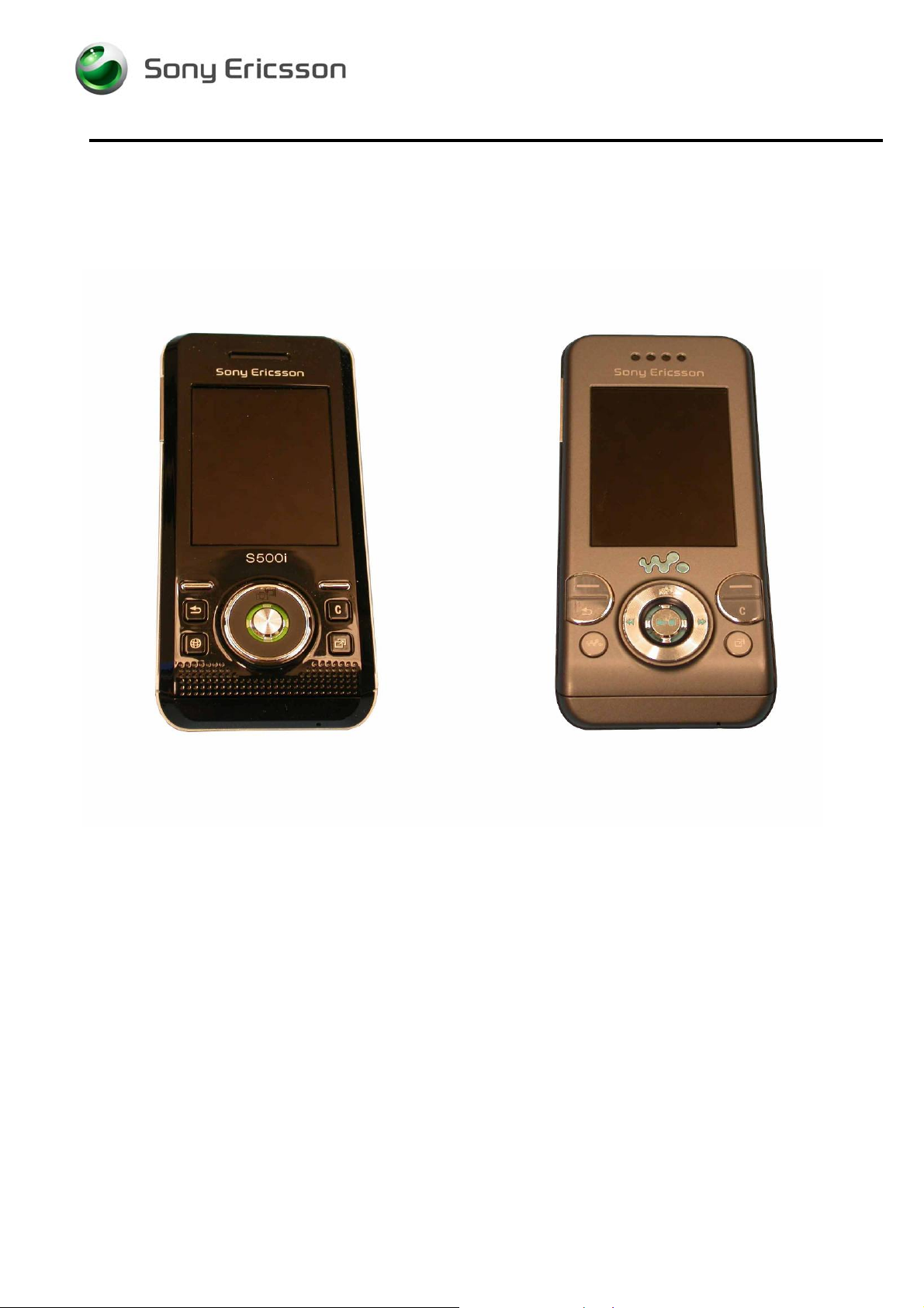
1 Introduction
1.1 View of S500 and W580
S500 W580
3/000 21-1/FEA 209 544/603 F
Company Internal
Communications AB
© Sony Ericsson Mobile
3(73)
Page 4

Working Instruction, Mechanical
1.2 Tools and Equipment
The following tools and equipment should be available while performing the procedures.
STANDARD TOOLS
• Style 2A Tweezers – Rounded Tip
• Nylon Pointer
• Torque Driver
• Dental Hook
• Plectrum
PRODUCT SPECIFIC TOOLS
• Coaxial Cable Removal Tool
• JCIS No. 0 Screw Bit
ESD EQUIPMENT
Protect the phone from ESD damages whenever it has
been opened by using:
• ESD-wristband
• ESD-gloves
LABEL EQUIPMENT
The following special equipment is required when replacing
or installing a new label:
• Hot air device
• Zebra printer connected to computer
3/000 21-1/FEA 209 544/603 F
Company Internal
Communications AB
© Sony Ericsson Mobile
4(73)
Page 5

Working Instruction, Mechanical
1.3 General Cautions
The following cautions are considered to be generic for all products and will not be repeated in the
Disassembly, Reassembly, and Replacements sections:
• S
WITCH OFF THE PHONE AND REMOVE ANY MEMORY STICK BEFORE THE START OF THE DISASSEMBLY!
• KEEP ALL CONTACT SURFACES CLEAN!
• BE CAREFUL WHEN USING TOOLS LIKE THE DENTIST HOOK, TWEEZERS, PRY TOOLS, ETC. TO AVOID
SCRATCHES OR DAMAGE TO THE EXTERIOR AND INTERIOR PARTS OF THE PHONE!
E CAREFUL NOT TO DAMAGE ANY CONTACT SPRINGS!
• B
• REMEMBER TO REMOVE THE PROTECTION FILMS ON NEW PARTS SUCH AS THE FRONT COVER AND LCD!
• NEVER TOUCH THE DISPLAY GLASS!
1.4 Adhesives
Use a dentist hook, the tweezers, and/or a nylon pointer to remove old adhesives.
Clean the surface with isopropyl alcohol before attaching new adhesives.
1.5 Using Hand and ESD Protection
When handling this product, keep all surfaces clean of dirt, dust, debris, and hand oil. Use
appropriate ESD precautions when working on this product. The use of finger cots or gloves, an ESD
mat, and an ESD wrist strap are required at minimum.
1.6 Protection of Displays, Lenses, and Windows
Any time the screen portion of a display assembly, the windows of a display cover, or a camera lens
is unprotected and exposed, add a protective film over the exposed part to reduce the amount of
dust, finger prints, debris, and/or damage that the part may obtain.
1.7 Acceptable Pry Tools
Whenever the phrase “pry tool” is used, a nylon pointer or a front opening tool may be used
depending on the user’s preference.
3/000 21-1/FEA 209 544/603 F
© Sony Ericsson Mobile Communications AB
5(73)
Page 6
Working Instruction, Mechanical
2 Disassembly
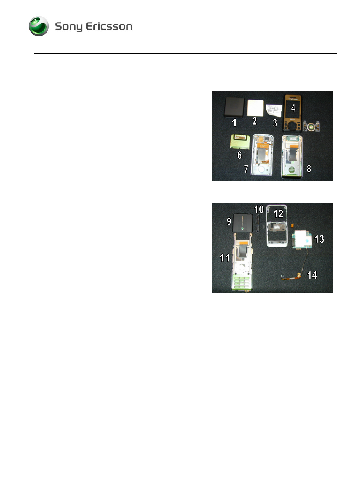
2.1 Overview
Perform the disassembly in the following order:
Upper Half of Phone
• Remove Battery Cover (1)
• Remove Battery (2)
• Remove Label (3)
• Remove Front Cover (4)
• Remove Camera Cover (6)
• Remove 6 Front Cover Screws (not shown)
• Separate Front Frame (7) and Rear Frame / Hinge
Assembly (8)
Lower Half of Phone
• Remove Upper Rear Cover (9)
• Remove 4 Rear Frame Screws (not shown)
• Remove Chin Cover (10)
• Remove Hinge Assembly (11) from Rear Frame (12)
• Remove PC Board/Antenna Assembly (13 &14) from
Rear Frame (12)
• Remove Antenna/cable Assembly (14) from
PC Board (13)
3/000 21-1/FEA 209 544/603 F
Company Internal
Communications AB
© Sony Ericsson Mobile
6(73)
Page 7
Working Instruction, Mechanical
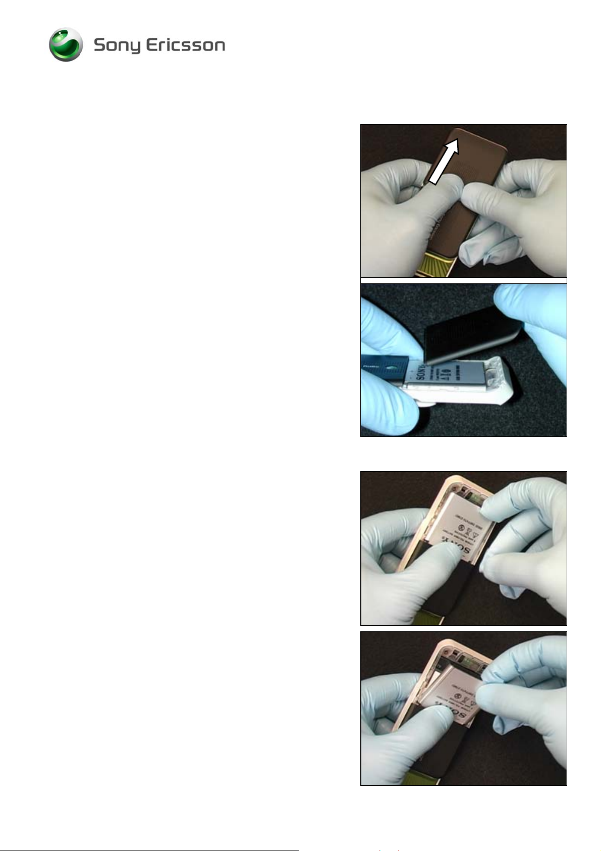
2.1.1 Battery Cover Removal
Use thumbs to push the battery cover down until it stops.
Lift the end of the battery cover to remove it.
2.1.2 Battery Removal
Use a finger to lift the battery up.
Pull the battery out of the battery cavity.
3/000 21-1/FEA 209 544/603 F
© Sony Ericsson Mobile Communications AB
7(73)
Page 8
Working Instruction, Mechanical
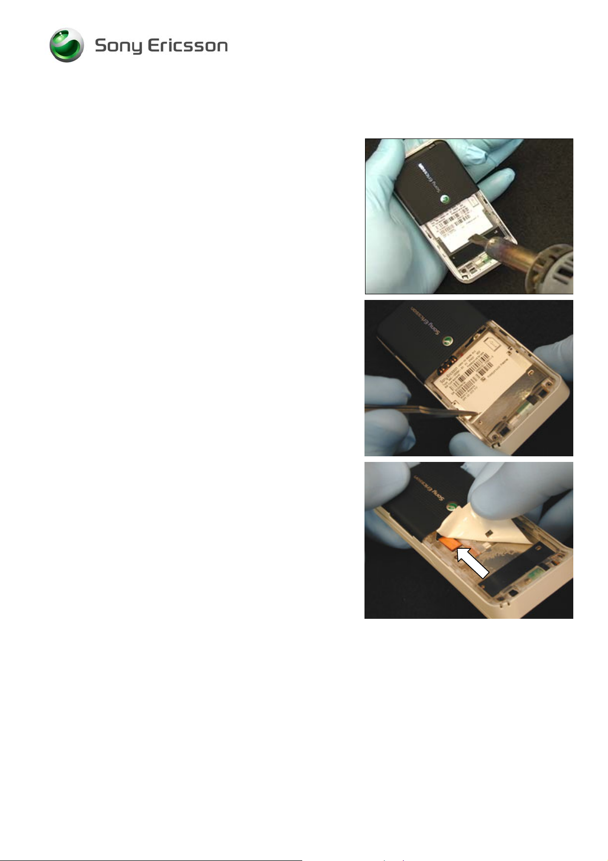
2.1.3 Label Removal
Apply hot air to soften the adhesive.
NOTE: THE USE OF HOT AIR IS OPTIONAL.
Use rounded tip tweezers to start the peeling up of the
label.
Once the peeling of the label is started, use your fingers to
remove the label.
NOTE: BE CAREFUL WHEN PULLING THE LABEL OFF
THE FLEX CONNECTOR.
3/000 21-1/FEA 209 544/603 F
© Sony Ericsson Mobile Communications AB
8(73)
Page 9
Working Instruction, Mechanical
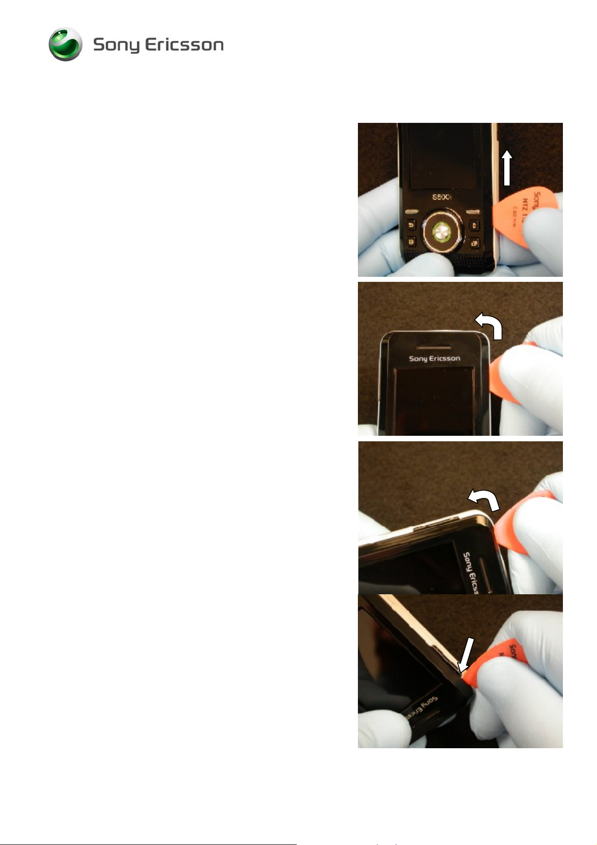
2.1.4 Front Cover Removal
Insert the plectrum in the front cover/ frame seam directly
beside the upper right navigation key.
Slide the plectrum toward the top corner to release the right
side latch.
Slide the plectrum around the top corner to release the
upper right corner latch.
Continue around the top left corner to release the upper left
corner latch.
Once the top of the volume key is reached remove the
plectrum from the seam.
STOP
HERE
3/000 21-1/FEA 209 544/603 F
© Sony Ericsson Mobile Communications AB
9(73)
Page 10

Working Instruction, Mechanical
STOP
Insert the plectrum in the front cover/ frame seam directly
beside the upper left navigation key.
Slide the plectrum toward the bottom of the volume key to
release the left side latch.
Slide the phone in the open position.
Rotate the upper end of the front cover away from the
phone just enough that the side latches are clear of the
frame
Then slide the cover down towards the keypad and off of
the frame.
NOTE: DO NOT ROTATE THE FRONT COVER TOO FAR
OR THE BOTTOM PEGS WILL BE DAMAGED.
Separate the navigation keypad from the front cover.
3/000 21-1/FEA 209 544/603 F
© Sony Ericsson Mobile Communications AB
10(73)
Page 11

Working Instruction, Mechanical
2.1.5 Camera Cover Removal
Locate the two tabs that hold the camera cover in place.
Use a rounded tipped tweezers to bend the metal tabs up.
Insert a plectrum between the camera cover and the frame
in the location shown to pry the cover up.
Pull the lifted end of the camera cover as shown to remove
the camera cover.
NOTE: ONCE THE CAMERA COVER IS REMOVED
THERE IS AN INCREASED RISK OF DAMAGING THE
SLIDING TEFLON TAPE ON THE HINGE. OPEN AND
CLOSE THE HINGE ONLY WHEN NECESSARY. KEEP
BOTH HALVES OF THE HINGE AS PARALLEL AS
POSSIBLE WHEN OPENING AND CLOSEING.
3/000 21-1/FEA 209 544/603 F
© Sony Ericsson Mobile Communications AB
11(73)
Page 12
Working Instruction, Mechanical
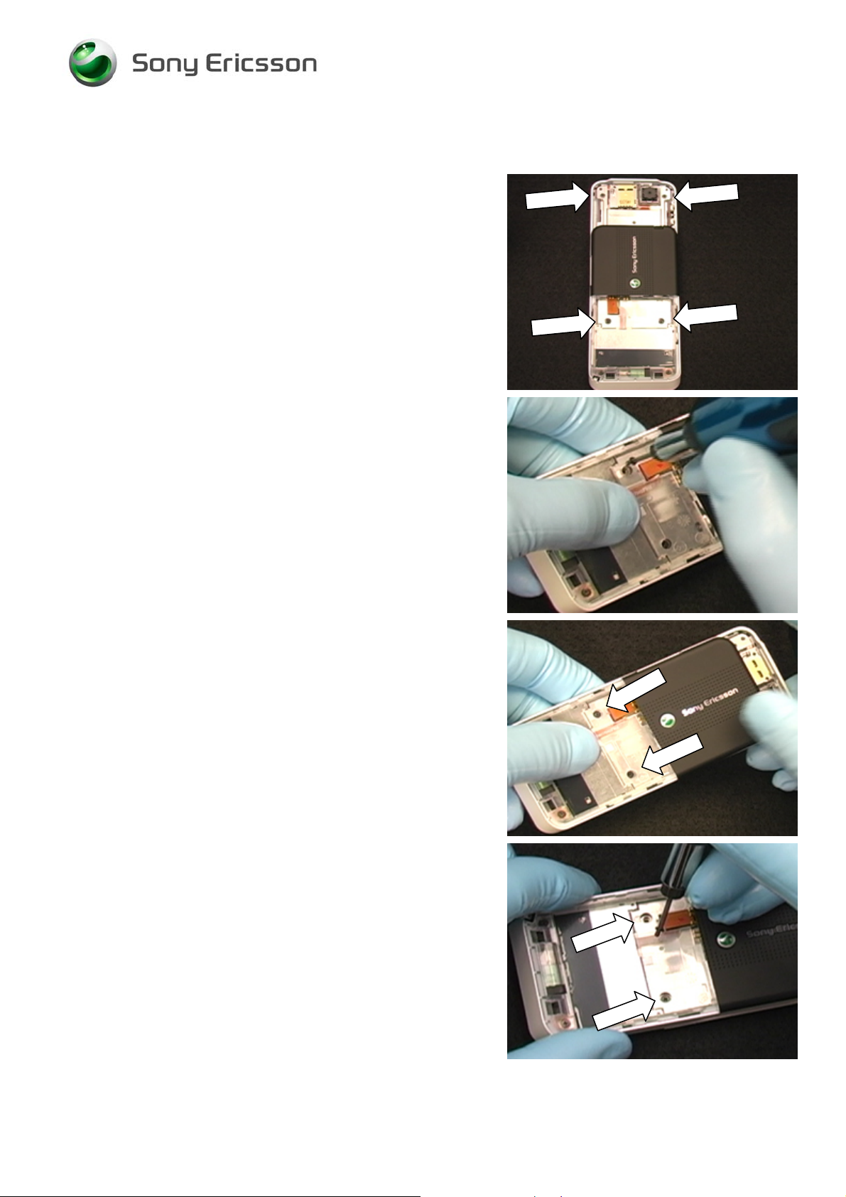
2.1.6 Front Cover Screw Removal (6 screws)
Slide the hinge into the open position, and then use a
torque wrench and a JCIS-0 bit to remove the 4 visible
screws.
NOTE: DO NOT REUSE THE SCREWS.
Use the magnetism of the wrench to pull the bottom screws
up through the hole in the hinge.
Slide the hinge partially closed until the remaining 2 screws
are visible.
NOTE: OPEN AND CLOSE THE HINGE ONLY WHEN
NECESSARY. KEEP BOTH HALVES OF THE HINGE AS
PARALLEL AS POSSIBLE WHEN OPENING AND
CLOSEING.
While holding the hinge in the partially closed position,
remove the screws.
NOTE: DO NOT REUSE THE SCREWS.
3/000 21-1/FEA 209 544/603 F
© Sony Ericsson Mobile Communications AB
12(73)
Page 13
Working Instruction, Mechanical
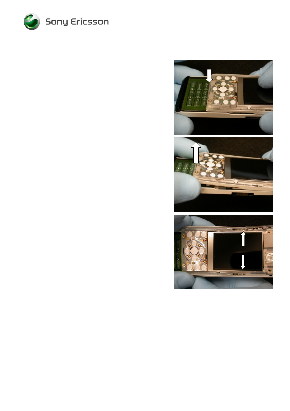
2.1.7 Front Frame Removal
Align
Slide the phone so that the bottom edge of the phone’s
upper half is aligned with the top edge of the 4, 5,& 6 row of
keys.
NOTE: THE TWO HALVES OF THE PHONE WILL HAVE
TO BE HELD IN PLACE TO MAINTAIN THIS
ALIGNMENT.
Lift the bottom edge of the phone’s upper half
approximately 10-15 mm.
NOTE: DO NOT SLIDE THE HINGE WHILE THE
BOTTOM END IS LIFTED. THIS COULD DAMAGE THE
TEFLON SLIDING TAPE
With the bottom edge the phone’s upper half lifted, locate
the two side latches holding the front frame on the hinge.
Latches
3/000 21-1/FEA 209 544/603 F
© Sony Ericsson Mobile Communications AB
13(73)
Page 14

Working Instruction, Mechanical
Latch 1
One at a time, press inward on the side of the front frame at
each of the latch locations to release the latches.
Latch 2
The front frame is now unlatched from the hinge.
NOTE: THE LCD ASSEMBLY MUST BE DETTACHED
BEFORE DISCONNECTING THE FLEX CONNECTION
BETWEEN THE FRONT HALF OF THE PHONE AND THE
HINGE ASSEMBLY TO REDUCE THE RISK OF FLEX
FILM DAMAGE.
Lay the front of the phone loosely on top of the hinge
3/000 21-1/FEA 209 544/603 F
© Sony Ericsson Mobile Communications AB
14(73)
Page 15
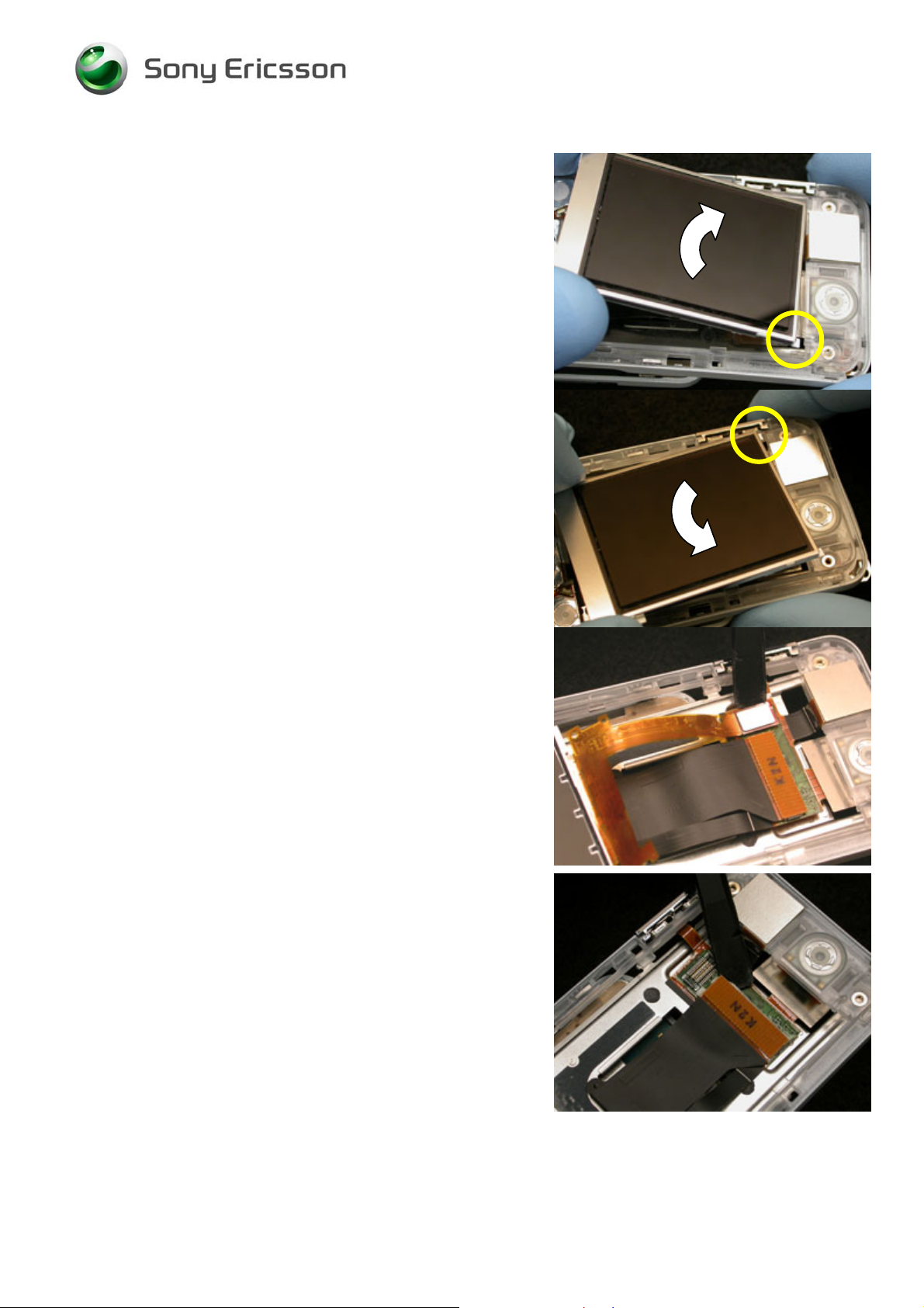
Working Instruction, Mechanical
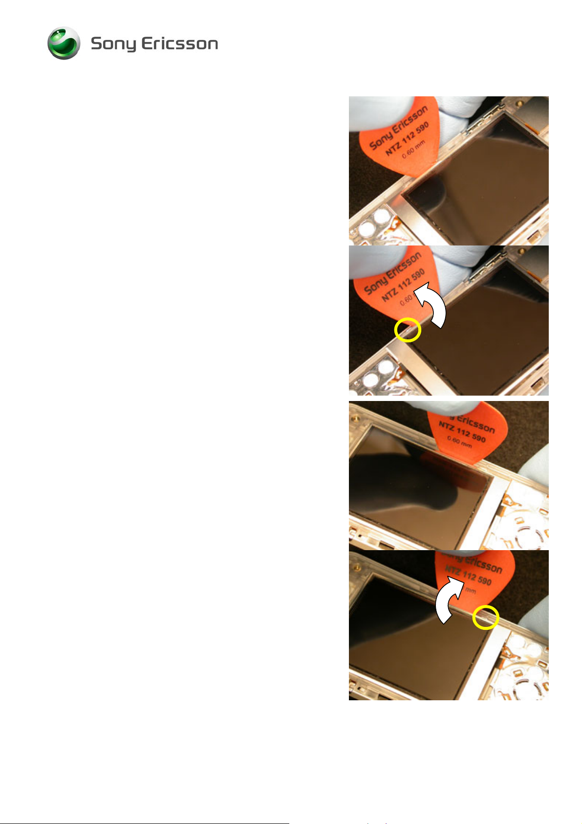
Insert the tip of the plectrum between the left side of the
LCD assembly and the front frame.
Rotate the plectrum away for the LCD to release the lower
left side retention feature.
Insert the tip of the plectrum between the right side of the
LCD and the front frame.
Rotate the plectrum away for the LCD to release the lower
right side retention feature.
3/000 21-1/FEA 209 544/603 F
© Sony Ericsson Mobile Communications AB
15(73)
Page 16
Working Instruction, Mechanical
Free the upper two LCD retention features by wiggling to
LCD to the left and right.
Once free, lift the LCD assembly out of the way and detach
its flex connection using a pry tool.
Set the detached LCD assembly aside.
Using a pry tool, carefully disconnect the hinge flex from the
bonzer flex.
NOTE: IN SOME CASES THERE ARE ADHESIVE
STRIPS THAT HOLD THIS CONNECTION TOGETHER.
BE CAREFUL NOT THE DAMAGE THE BONZER FLEX
OF THE HINGE FLEX WHEN TRYING THE SEPARATE
THE CONNECTION.
3/000 21-1/FEA 209 544/603 F
© Sony Ericsson Mobile Communications AB
16(73)
Page 17
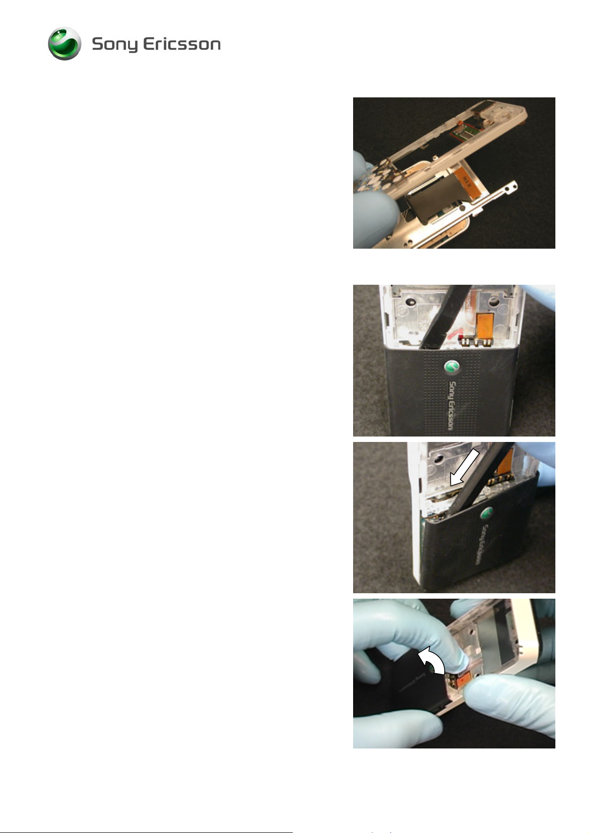
Working Instruction, Mechanical
Once the hinge flex is disconnected, remove the front
frame.
NOTE: OPEN AND CLOSE THE HINGE ONLY WHEN
NECESSARY. KEEP BOTH HALVES OF THE HINGE AS
PARALLEL AS POSSIBLE WHEN OPENING AND
CLOSEING.
2.1.8 Upper Rear Cover Removal
Insert a pry tool between the rear cover and the rear frame
at the location shown.
Push the pry tool into the seam and toward the left side of
the cover so that latch holding the left corner of the cover
releases.
Lift up on the rear cover to release the middle and right side
latches.
3/000 21-1/FEA 209 544/603 F
© Sony Ericsson Mobile Communications AB
17(73)
Page 18
Working Instruction, Mechanical
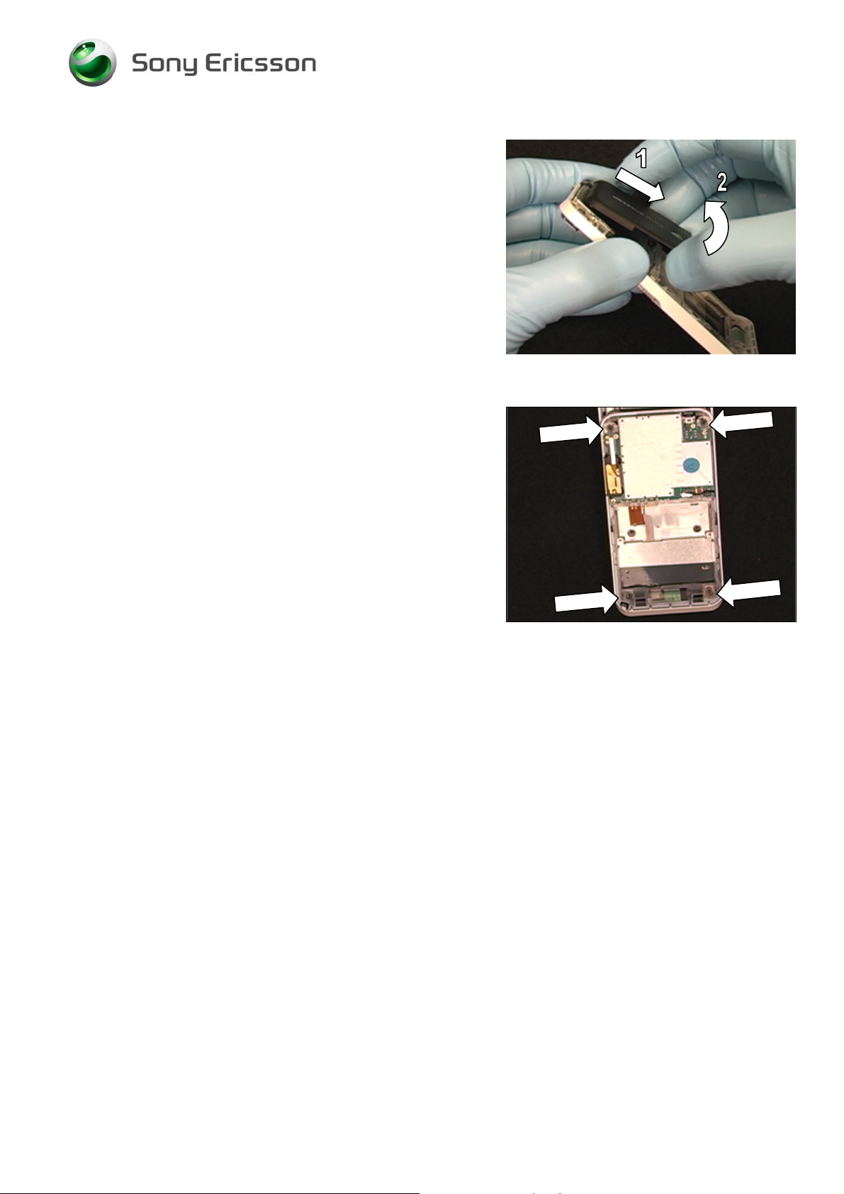
Pull the rear cover down and rotate the lifted end of the
cover away from the rear frame.
2.1.9 Rear Frame Screw Removal (4 screws)
Use a torque wrench and a JCIS-0 bit to remove the 4
screws.
NOTE: DO NOT REUSE THE SCREWS.
3/000 21-1/FEA 209 544/603 F
© Sony Ericsson Mobile Communications AB
18(73)
Page 19

Working Instruction, Mechanical
2.1.10 Chin Cover Removal
Insert the plectrum between the keypad and the left end of
the chin cover.
Using the plectrum, lift up of the left end of the chin cover to
get the chin cover to unsnap from the rear frame.
Remove the microphone gasket using your fingers.
3/000 21-1/FEA 209 544/603 F
© Sony Ericsson Mobile Communications AB
19(73)
Page 20

Working Instruction, Mechanical
2.1.11 Hinge Assembly Removal from Rear Frame
NOTE: OPEN AND CLOSE THE HINGE ONLY WHEN
NECESSARY. KEEP BOTH HALVES OF THE HINGE AS
PARALLEL AS POSSIBLE WHEN OPENING AND
CLOSEING.
With the hinge open and the keypad up, locate the metal
clips holding the hinge assembly on the rear frame.
Insert tweezers or a small screwdriver under one of the
metal clips and twist toward the center of the phone to
release the latch.
Insert tweezers or a small screwdriver under the other metal
clip and twist toward the center of the phone to release the
latch.
Lift the “non-keypad” end of the hinge assembly away from
the rear frame.
Use a pry tool to unplug the hinge-to-board connector.
3/000 21-1/FEA 209 544/603 F
© Sony Ericsson Mobile Communications AB
20(73)
Page 21
Working Instruction, Mechanical
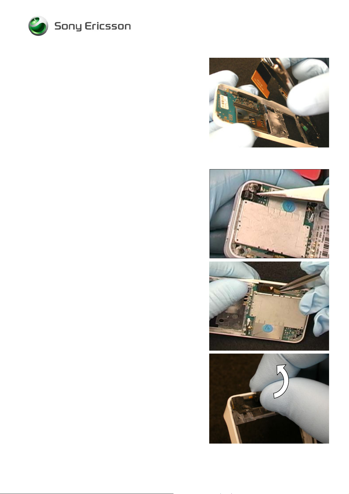
Lift the hinge assembly from the rear frame.
2.1.12 PC Board/Antenna assembly Removal from Rear Frame
Use tweezers to remove the power key.
Use tweezers to remove the Bluetooth tape.
Grip the middle of the antenna assembly and rotate it away
from the circuit board to free the antenna from the rear
frame
Leave the antenna sitting on the rear frame over its cavity.
3/000 21-1/FEA 209 544/603 F
© Sony Ericsson Mobile Communications AB
21(73)
Page 22
Working Instruction, Mechanical
Use a pry tool to release the board from the latches beside
the SIM connector.
Lift the circuit board, coaxial cable, and antenna as one unit
from the rear frame.
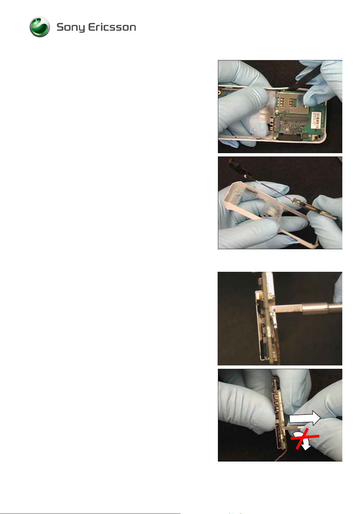
2.1.13 Antenna/Cable Assembly Removal from PC Board
NOTE: USE THE REMOVAL TOOL OR THE BOARD
CONNECTOR MAY BE DAMAGED.
Insert the slot of the tool onto the end of the coaxial cable
connector.
Pull the connector directly away from the PC board.
NOTE: DO NOT ROTATE.
3/000 21-1/FEA 209 544/603 F
© Sony Ericsson Mobile Communications AB
22(73)
Page 23

Working Instruction, Mechanical
3 Part Replacement
3.1 Bluetooth Antenna
Remove the battery cover, battery, and upper rear cover as
instructed in disassembly procedure 2.1.1, 2.1.2, and 2.1.8.
Removal
Remove the Bluetooth tape using tweezers.
Remove the Bluetooth antenna from the rear frame by
sliding it toward the edge of the frame.
Installation
Insert the bent pins of the antenna into the slots of the
frame.
3/000 21-1/FEA 209 544/603 F
Company Internal
Communications AB
© Sony Ericsson Mobile
23(73)
Page 24

Working Instruction, Mechanical
Using a nylon pointer, push the antenna into place.
Install the Bluetooth tape using tweezers. Align the tape
with the inside edge of the system connector and leave two
holes exposed.
Reinstall the upper rear cover, battery, and battery cover as
instructed in reassembly procedure 4.1.5, 4.1.12, and
4.1.13.
3.2 Bonzer Flex
Removal
Perform sections 2.1.1-2.1.7 of the disassembly procedure
Perform the removal portion of the Volume Key
Replacement procedure
Pull the volume key switches out of the slot of the front
frame.
Align
Edge
Push the camera out of its cavity.
3/000 21-1/FEA 209 544/603 F
© Sony Ericsson Mobile Communications AB
24(73)
Page 25

Working Instruction, Mechanical
Fold the camera portion of the flex in front of the LCD
connector.
Lift the portion of the flex containing the memory stick
holder from the front frame.
Fold the top corners of the dome foil a small amount off the
speaker box.
Push the bottom of the speaker box from the frame.
3/000 21-1/FEA 209 544/603 F
© Sony Ericsson Mobile Communications AB
25(73)
Page 26

Working Instruction, Mechanical
Installation
Obtain a new bonzer flex of the correct connector type.
Use the colored dots on the flexs to determine with bonzer
flex can be used with which hinge flex:
• If the hinge flex has no dot or a pink dot, use a
bonzer flex with no dot.
• If the hinge flex has a white dot or a yellow dot, use a
bonzer flex with a yellow dot.
Fold the top corners of the dome foil a small amount off the
speaker box.
Insert the top of the navigation keypad/ speaker box into the
cavity on the frame with the keypad in front of the frame and
the speaker box in back of the frame.
Fold the top corners of the navigation keypad down onto the
frame.
3/000 21-1/FEA 209 544/603 F
© Sony Ericsson Mobile Communications AB
26(73)
Page 27

Working Instruction, Mechanical
Insert the camera into its cavity.
Insert the volume switches into their cavity.
Place the memory stick holder portion of the flex within its
retaining features in the front frame.
Perform the installation portion of the Volume Key
Replacement procedure
Perform the reassembly procedure starting at section 4.1.7
3/000 21-1/FEA 209 544/603 F
© Sony Ericsson Mobile Communications AB
27(73)
Page 28

Working Instruction, Mechanical
3.3 Camera
Removal
Remove the Front Cover and the Camera Cover as shown
in Disassembly sections 2.1.4-2.1.5.
Align the pegs of the camera removal tool with the slots in
the camera socket to determine the correct orientation.
Insert the pegs into the slots and press the tool completely
onto the camera.
Remove the tool and the camera from the socket.
Installation
Align the tab on the camera with the slot of the socket.
3/000 21-1/FEA 209 544/603 F
© Sony Ericsson Mobile Communications AB
28(73)
Page 29

Working Instruction, Mechanical
Insert the camera into the socket and push it down.
Replace the Camera Cover and Front Cover as shown in
Reassembly section 4.1.9 - 4.1.10.
3.4 Camera Cover
Removal
Perform sections 2.1.4 - 2.1.5 of the disassembly
procedure.
Obtain a new Camera Cover.
Installation
Perform sections 4.1.9 - 4.1.10 of the reassembly
procedure.
3.5 Chin Cover
Removal
Perform section 2.1.10 of the disassembly procedure.
Obtain a new Chin Cover.
Installation
Perform section 4.1.6 of the reassembly procedure.
3/000 21-1/FEA 209 544/603 F
© Sony Ericsson Mobile Communications AB
29(73)
Page 30

Working Instruction, Mechanical
3.6 Coaxial Cable and Antenna
Removal
Perform sections 2.1.4 - 2.1.13 of the disassembly
procedure.
NOTE: IF THE COAXIAL CABLE CONNECTOR IS
REMOVED FROM THE ANTENNA, THEN THE ANTENNA
MUST BE REPLACED.
Installation
NOTE: CONNECT THE END OF THE COAXIAL CABLE
TO THE ANTENNA THAT HAS THE METAL SLEEVE
CLOSEST TO IT
Insert the connector into the slot of the tool, and then snap
the connector onto the antenna.
Perform sections 4.1.1 – 4.1.13 of the reassembly
procedure
3.7 Front Cover
Removal
Perform section 2.1.4 of the disassembly procedure.
Installation
Obtain a new Front Cover.
Perform section 4.1.10 of the reassembly procedure.
3/000 21-1/FEA 209 544/603 F
© Sony Ericsson Mobile Communications AB
30(73)
Page 31

Working Instruction, Mechanical
3.8 Front Frame
Removal
Perform sections 2.1.1 -2.1.7 of the disassembly procedure.
Perform the removal portion of the Volume Key
Replacement procedure
Perform the removal portion of the Bonzer Flex
Replacement procedure
Perform the removal portion of the Receiver and Gasket
Replacement procedure
Obtain a new Front frame.
Installation
Perform the installation portion of the Receiver and Gasket
Replacement procedure
Perform the installation portion of the Bonzer Flex
Replacement procedure
Perform the installation portion of the Volume Key
Replacement procedure
Perform the reassembly procedure starting at section 4.1.7
3/000 21-1/FEA 209 544/603 F
© Sony Ericsson Mobile Communications AB
31(73)
Page 32

Working Instruction, Mechanical
3.9 Hinge Assembly
Removal
Perform sections 2.1.1 -2.1.11 of the disassembly
procedure
Installation
Obtain a new hinge assembly with the correct connector
type on the hinge flex. Use the colored dots on the flexs to
determine with hinge flex can be used with the bonzer flex
in the phone:
• If the bonzer flex has no dot or a pink dot, use a
hinge flex with no dot.
• If the bonzer flex has a white dot or a yellow dot, use
a hinge flex with a white dot.
Remove the protective tape covers from the Teflon tape.
NOTE: OPEN AND CLOSE THE HINGE ONLY WHEN
NECESSARY. KEEP BOTH HALVES OF THE HINGE AS
PARALLEL AS POSSIBLE WHEN OPENING AND
CLOSEING TO PREVENT DAMAGING THE TEFLON
TAPE.
Perform the installation portion of the Wear Strip
Replacement procedure
Perform sections 4.1.3 -4.1.13 of the reassembly procedure
3/000 21-1/FEA 209 544/603 F
© Sony Ericsson Mobile Communications AB
32(73)
Page 33

Working Instruction, Mechanical
3.10 Keypad
Removal
Remove the Chin Cover and microphone gasket as
instructed in section 2.1.10 of the disassembly procedure.
Use a plectrum to lift a corner of the keypad enough to grip
onto the keypad.
Carefully peel the keypad off the hinge assembly.
Align the tabs and notches on the keypad with the tabs and
holes indicated on the hinge assembly.
Apply pressure over the surface of the keypad so that a
good bond to the hinge assembly occurs.
Reinstall the microphone gasket and chin cover as
instructed in section 4.1.6 of the reassembly procedure.
3/000 21-1/FEA 209 544/603 F
© Sony Ericsson Mobile Communications AB
33(73)
Page 34

Working Instruction, Mechanical
3.11 LCD Assembly
Removal
Remove the Front Cover as instructed in section 2.1.4 of
the disassembly procedure.
Insert the tip of the plectrum between the left side of the
LCD assembly and the front frame.
Rotate the plectrum away for the LCD to release the lower
left side retention feature.
Insert the tip of the plectrum between the right side of the
LCD and the front frame.
Rotate the plectrum away for the LCD to release the lower
right side retention feature.
3/000 21-1/FEA 209 544/603 F
© Sony Ericsson Mobile Communications AB
34(73)
Page 35

Working Instruction, Mechanical
Free the upper two LCD retention features by wiggling to
LCD to the left and right.
Once free, lift the LCD assembly out of the way and detach
its flex connection using a pry tool.
Installation
Orient the LCD as shown and plug the LCD’s flex into the
bonzer flex.
3/000 21-1/FEA 209 544/603 F
© Sony Ericsson Mobile Communications AB
35(73)
Page 36

Working Instruction, Mechanical
Fold the LCD so that it lays over its cavity.
Insert the upper two LCD retention features into their slots
in the front frame by wiggling to LCD to the right and then
the left.
Insert the tip of the plectrum between the left side of the
LCD assembly and the front frame.
3/000 21-1/FEA 209 544/603 F
© Sony Ericsson Mobile Communications AB
36(73)
Page 37

Working Instruction, Mechanical
Rotate the plectrum towards the LCD to insert the lower left
side retention feature into its slot in the front frame.
Insert the tip of the plectrum between the right side of the
LCD and the front frame.
Rotate the plectrum towards the LCD to insert the lower
right side retention feature into its slot in the front frame.
Reinstall the front cover as instructed in section 4.1.10 of
the reassembly procedure.
3/000 21-1/FEA 209 544/603 F
© Sony Ericsson Mobile Communications AB
37(73)
Page 38

Working Instruction, Mechanical
3.12 Liquid Intrusion Indicator
Removal
Perform sections 2.1.1 -2.1.11 of the disassembly
procedure
Remove the old liquid intrusion indicator.
Installation
Align the bottom, left corner of the new indicator with the
edge of the slot in the hinge.
Perform sections 4.1.3 -4.1.13 of the reassembly procedure
3.13 Main Keypad Flex
Removal
NOTE:
Perform sections 2.1.1 -2.1.11 of the disassembly
procedure.
Perform the removal portion of the Keypad Replacement
procedure
Use a pry tool to disconnect the flex connection.
THE MAIN KEYPAD FLEX CANNOT BE REUSED!
Use a pry tool to remove the vibrator.
3/000 21-1/FEA 209 544/603 F
© Sony Ericsson Mobile Communications AB
38(73)
Page 39

Working Instruction, Mechanical
Lift the microphone flex off the hinge.
Pull the vibrator pads through the slot in the hinge.
Peel the dome foil off the hinge.
Pull the flex connector through the hole in the hinge.
Remove any adhesive residue from the hinge assembly.
Remove the microphone from the old keypad flex by
performing the removal portion of the Microphone
Replacement procedure
3/000 21-1/FEA 209 544/603 F
© Sony Ericsson Mobile Communications AB
39(73)
Page 40

Working Instruction, Mechanical
Installation
Obtain a new main keypad flex.
NOTE: THE COLORED DOT COMBINATION BETWEEN
ON THE HINGE FLEX AND MAIN KEYPAD FLEX DOES
NOT MATTER. ANY COLOR COMBINATION WILL
WORK.
Install the microphone in the new keypad flex by performing
the installation portion of the Microphone Replacement
procedure
Push the flex connector through the hole in the hinge.
Using the features around the hinge assembly’s keypad
area for alignment, place the keypad flex on the hinge.
Apply pressure over the dome foil portion of the keypad flex
so that a good bond is formed
3/000 21-1/FEA 209 544/603 F
© Sony Ericsson Mobile Communications AB
40(73)
Page 41

Working Instruction, Mechanical
Insert the vibrator connector through the slot.
Orient the vibrator so that its spring fingers are toward the
vibrator contact pads and insert the vibrator into its cavity.
Push the vibrator down into place.
Plug the keypad flex to the hinge flex.
Perform sections 4.1.3 -4.1.13 of the reassembly procedure
Perform the installation portion of the Keypad Replacement
procedure
3/000 21-1/FEA 209 544/603 F
© Sony Ericsson Mobile Communications AB
41(73)
Page 42

Working Instruction, Mechanical
3.14 Memory Stick Cover
Removal
Remove the front cover and camera cover as shown in
sections 2.1.4 - 2.1.5 of the Disassembly procedure.
Pull the memory stick cover out of its cavity.
Rotate the memory stick cover down to free the inside latch
from the peg on the frame.
Pull the cover out of the hole.
Installation
Insert the tabbed end of the cover through the hole.
3/000 21-1/FEA 209 544/603 F
© Sony Ericsson Mobile Communications AB
42(73)
Page 43

Working Instruction, Mechanical
Twist the cover and push the tab down behind the peg on
the carrier.
Make sure the tab is behind the peg.
Push the cover into its cavity.
Replace the Camera Cover and Front Cover as in 4.1.9-
4.1.10 of the reassembly procedure.
3/000 21-1/FEA 209 544/603 F
© Sony Ericsson Mobile Communications AB
43(73)
Page 44

Working Instruction, Mechanical
3.15 Microphone
Removal
Remove the Chin Cover and Microphone Gasket as shown
in section 2.1.10 of the Disassembly procedure.
Perform the removal portion of the Keypad Replacement
procedure
Insert a plectrum between the microphone and the flex.
Hold the flex with one finger while working the microphone
pins out of the holes.
NOTE:
WHEN REMOVING THE MICROPHONE
Installation
Orient the microphone so the pins are toward the phone
and the side of the microphone that its contact pins are
closest too is toward the keypad dome foil.
LIMIT THE AMOUNT OF STRESS ON THE KEYPAD FLEX
.
Insert the pins into the holes.
3/000 21-1/FEA 209 544/603 F
© Sony Ericsson Mobile Communications AB
44(73)
Page 45

Working Instruction, Mechanical
Push the microphone down completely.
Perform section 4.1.6 of the reassembly procedure
Perform the installation portion of the Keypad Replacement
procedure
3.16 Microphone Gasket
Removal
Remove the chin cover and microphone gasket as
instructed in disassembly procedure 2.1.10.
Installation
Install the microphone gasket and the chin cover as
instructed in reassembly procedure 4.1.6.
3.17 Navigation Keypad
Removal
Remove the battery cover, battery, and front cover as
instructed in disassembly procedure 2.1.1, 2.1.2, and 2.1.4.
Installation
Obtain a new navigation keypad.
Reinstall the front cover, battery, and battery cover as
instructed in reassembly procedure 4.1.10, 4.1.12, and
4.1.13
3/000 21-1/FEA 209 544/603 F
© Sony Ericsson Mobile Communications AB
45(73)
Page 46

Working Instruction, Mechanical
3.18 Power Key
Removal
Remove the battery cover, battery, and upper rear cover as
instructed in disassembly procedure 2.1.1, 2.1.2, and 2.1.8.
Using tweezers, remove the power key.
Peg in
Installation
Hole
Insert the peg of the power key into the hole on the rear
frame and press power key into place.
Reinstall the upper rear cover, battery, and battery cover as
instructed in reassembly procedure 4.1.5, 4.1.12, and
4.1.13.
3.19 Rear Frame / Pad
Removal
Perform sections 2.1.1-2.1.12 of the disassembly
procedure
Installation
NOTE: WHEN REPLACING THE REAR FRAME, BE
SURE TO INSTALL A COAXIAL CABLE GROUND PAD
IN THE COAXIAL CABLE SLOT.
Using tweezers, align the end of the coaxial cable ground
pad with the end of the plastic rail in the frame as shown.
Press the coaxial cable ground pad into the cable slot.
Perform the reassembly procedure starting at section 4.1.2
3/000 21-1/FEA 209 544/603 F
© Sony Ericsson Mobile Communications AB
46(73)
Page 47

Working Instruction, Mechanical
3.20 Receiver and Gasket
Removal
Perform sections 2.1.1-2.1.7 of the disassembly procedure
Perform the removal portion of the Volume Key
Replacement procedure
Perform the removal portion of the Bonzer Flex
Replacement procedure
Push the receiver and gasket out of the cavity on the front
frame.
Separate the receiver and the gasket.
Installation
Insert the receiver into the receiver gasket.
Insert the receiver/gasket assembly into the cavity on the
front frame.
Perform the installation portion of the Bonzer Flex
Replacement procedure
Perform the installation portion of the Volume Key
Replacement procedure
Perform the reassembly procedure starting at section 4.1.7
3/000 21-1/FEA 209 544/603 F
© Sony Ericsson Mobile Communications AB
47(73)
Page 48

Working Instruction, Mechanical
3.21 System Connector
Removal
Perform sections 2.1.1-2.1.12 of the disassembly
procedure
Pull the system connector off of the PC board.
Installation
Push the system connector onto the PC board.
Perform the reassembly procedure starting at section 4.1.2
3.22 Upper Rear Cover
Removal
Remove the battery cover, battery, and upper rear cover as
instructed in disassembly procedure 2.1.1, 2.1.2, and 2.1.8.
Installation
Reinstall the upper rear cover, battery, and battery cover as
instructed in reassembly procedure 4.1.5, 4.1.12, and
4.1.13
3/000 21-1/FEA 209 544/603 F
© Sony Ericsson Mobile Communications AB
48(73)
Page 49

Working Instruction, Mechanical
3.23 Vibrator
Removal
Perform sections 2.1.1-2.1.11 of the disassembly
procedure
Gently lift the vibrator out of its cavity.
Installation
Orient the vibrator so that its spring fingers are toward the
vibrator contact pads and insert the vibrator into its cavity.
Push the vibrator down into place.
Perform the reassembly procedure starting at section 4.1.3
3/000 21-1/FEA 209 544/603 F
© Sony Ericsson Mobile Communications AB
49(73)
Page 50

Working Instruction, Mechanical
3.24 V olume Key
Removal
Remove the front cover as instructed in disassembly
procedure 2.1.5
Lifting from the bottom of the volume key, rotate it towards
the display to free it from its cavity.
Installation
Orient the volume key so that the shape of the key
corresponds to the shape of its cavity in the frame.
Work the volume key into its opening so that the features at
each end of the volume key mate with the features of the
frame as shown.
Reinstall the front cover as instructed in reassembly
procedure 4.1.10
3/000 21-1/FEA 209 544/603 F
© Sony Ericsson Mobile Communications AB
50(73)
Page 51

Working Instruction, Mechanical
3.25 Wear Strips
Removal
Perform sections 2.1.1-2.1.11 of the disassembly
procedure
NOTE: DO NOT REUSE WEAR STRIPS!
Grip the curved end of the wear strip.
Pull the strip off the hinge assembly.
Installation
NOTE: THE CURVED END OF THE WEAR STRIPS GO
TOWARDS THE END OF THE HINGE ASSEMBLY
WHERE THE MICROPHONE IS LOCATED!
NOTE: THERE IS A LEFT SIDE WEAR STRIP AND A
RIGHT SIDE WEAR STRIP.
Align the tabs on the hinge assembly with the holes in the
wear strip.
Snap the wear strip onto the hinge assembly.
Perform the reassembly procedure starting at section 4.1.3
3/000 21-1/FEA 209 544/603 F
© Sony Ericsson Mobile Communications AB
51(73)
Page 52

Working Instruction, Mechanical
4 Reassembly
4.1 Overview
Perform the reassembly in the following order:
Lower half of phone
• Attach antenna/coax cable assembly(6) to PC Board (5)
• Install PC Board/Antenna assembly (5 & 6) into Rear
Frame (4)
• Attach Hinge Assembly (3) to Rear Frame (4)
• Install 4 Rear Frame Screws (not shown)
• Install Upper Rear Cover (1)
• Install Chin Cover (2)
Upper half of phone
• Attach Front Frame (14) and Rear Frame / Hinge
Assembly (15)
• Install 6 Front Cover Screws (not shown)
• Install Camera Cover (13)
• Install Front Cover (12)
• Install Label (11)
• Install Battery (10)
• Install Battery Cover (9)
3/000 21-1/FEA 209 544/603 F
Company Internal
Communications AB
© Sony Ericsson Mobile
52(73)
Page 53

Working Instruction, Mechanical
4.1.1 Antenna/Cable Assembly Installation to PC Board
Insert the connector on the end of the antenna coaxial cable
into the slot in the coax removal tool.
Using the tool, snap the connector onto the PC board.
Rotate the coax cable so that it is oriented to the circuit
board as shown.
3/000 21-1/FEA 209 544/603 F
© Sony Ericsson Mobile Communications AB
53(73)
Page 54

Working Instruction, Mechanical
4.1.2 PC Board and Antenna Installation
Insert the side of the PC board with the system connector
into place under the Bluetooth antenna.
NOTE: there is a slot in the edge of the rear frame in which
the system connector sits.
Position the coaxial cable so that it passes through the hole
formed between the notch in the circuit board and the rear
frame.
Work the side of the circuit board opposite the system
connector into the rear frame by pulling the portion of the
rear frame indicated away for the circuit board so that the
two snaps clear the board’s edge.
NOTE: THE TWO SNAPS SHOULD REST AGAINST ITS SIM
CONNECTOR SIDE OF THE CIRCUIT BOARD.
3/000 21-1/FEA 209 544/603 F
© Sony Ericsson Mobile Communications AB
54(73)
Page 55

Working Instruction, Mechanical
Snap the antenna assembly into its cavity.
Push the coaxial cable down into the slot of the frame using
a pry tool.
Insert the peg of the power key into the hole on the rear
frame and press it into place
Peg in
Hole
Install the Bluetooth tape using tweezers. Align the tape
with the inside edge of the system connector and leave two
holes exposed.
3/000 21-1/FEA 209 544/603 F
© Sony Ericsson Mobile Communications AB
Align
Edge
55(73)
Page 56

Working Instruction, Mechanical
4.1.3 Hinge Assembly Installation to Rear Frame
Plug the hinge flex connector into the socket on the PC
board.
Lay the hinge assembly on top of the frame
Press the end of the hinge assembly that contains the
microphone into the rear frame.
NOTE:
UNDER THE TABS OF THE ANTENNA PLASTIC.
MAKE SURE THE MICROPHONE FLEX IS
Snap the tab on one side of the frame in the slot on the
hinge.
3/000 21-1/FEA 209 544/603 F
© Sony Ericsson Mobile Communications AB
56(73)
Page 57

Working Instruction, Mechanical
Snap the other side into place.
4.1.4 Rear Frame Screw Installation (4 Screws)
NOTE: DO NOT REUSE THESE SCREWS.
Use 8 N*cm and a JCIS No. 0 bit to install the four new
screws.
3/000 21-1/FEA 209 544/603 F
© Sony Ericsson Mobile Communications AB
57(73)
Page 58

Working Instruction, Mechanical
4.1.5 Upper Rear Cover Installation
Insert the two indicated tabs on the upper rear cover into
the slots on the frame.
Rotate the cover down toward the phone.
3/000 21-1/FEA 209 544/603 F
© Sony Ericsson Mobile Communications AB
58(73)
Page 59

Working Instruction, Mechanical
Snap the remaining 3 tabs into place.
(Shown in pictures 1, 2, and 3)
3/000 21-1/FEA 209 544/603 F
© Sony Ericsson Mobile Communications AB
59(73)
Page 60

Working Instruction, Mechanical
4.1.6 Chin Cover Installation
Orient the microphone gasket so that the wider side of the
gasket toward the keypad.
Press the gasket over the microphone as shown.
Insert the tabs of the chin cover into the slots.
Push down on the cover to snap all the tabs into place.
3/000 21-1/FEA 209 544/603 F
© Sony Ericsson Mobile Communications AB
60(73)
Page 61

Working Instruction, Mechanical
4.1.7 Front Frame Installation
NOTE: ONLY BONZER FLEXS THAT HAVE NO DOTS
OR PINK DOTS REQUIRE THE TWO PIECES OF
CONNECTION TAPE BE ADDED.
Bonzer Flex With No Dot or Pink Dot Only:
Remove any remains of the two pieces of connector tape
from each half of the hinge to bonzer flex connection.
Bonzer Flex With No Dot or Pink Dot Only:
Add two new pieces of tape around the connection on the
bonzer flex as shown.
NOTE: ALIGN THE EDGE OF THE TAPE WITH THE
EDGE OF THE FLEX AS INDICATED.
Bonzer Flex With No Dot or Pink Dot Only:
Remove the protective film from each piece of tape.
Align
Edges
3/000 21-1/FEA 209 544/603 F
© Sony Ericsson Mobile Communications AB
61(73)
Page 62

Working Instruction, Mechanical
Position the front frame over the hinge assembly so that the
bonzer/hinge flex connection lines up.
Use the colored dots on the flexs to verify that you have a
valid bonzer flex/hinge flex combination:
• If the hinge flex has no dot or a pink dot, the bonzer
flex must have no dot or a pink dot.
• If the hinge flex has a white dot or a yellow dot, the
bonzer flex must have white dot or a yellow dot.
Plug the hinge flex into the corresponding bonzer flex
connection.
Bonzer Flex With No Dot or Pink Dot Only:
Apply a small amount of pressure so that the tape bonds.
Orient the LCD as shown and plug the LCD’s flex into the
bonzer flex.
Fold the LCD so that it lays over its cavity.
3/000 21-1/FEA 209 544/603 F
© Sony Ericsson Mobile Communications AB
62(73)
Page 63

Working Instruction, Mechanical
Insert the upper two LCD retention features into their slots
in the front frame by wiggling to LCD to the right and then
the left.
Insert the tip of the plectrum between the left side of the
LCD assembly and the front frame.
Rotate the plectrum towards the LCD to insert the lower left
side retention feature into its slot in the front frame.
3/000 21-1/FEA 209 544/603 F
© Sony Ericsson Mobile Communications AB
63(73)
Page 64

Working Instruction, Mechanical
Insert the tip of the plectrum between the right side of the
LCD and the front frame.
Rotate the plectrum towards the LCD to insert the lower
right side retention feature into its slot in the front frame.
Holding the front frame and hinge assembly at the top, slide
the phone closed.
Press in on the front frame at two side latches to get the
hinge and front frame latched together.
3/000 21-1/FEA 209 544/603 F
© Sony Ericsson Mobile Communications AB
64(73)
Page 65

Working Instruction, Mechanical
4.1.8 Front Frame Screw Installation (6 Screws)
NOTE: DO NOT REUSE THESE SCREWS.
NOTE: INSERT THE SCREWS IN THE ORDER SHOWN
IN THE FOLLOWING TWO PHOTOS.
Push the hinge closed a small amount until the screw holes
on the front frame are visible. Use 6 N*cm and a JCIS No.
0 bit to install the new screws.
Push the hinge open and install the remaining four screws.
4.1.9 Camera Cover Installation
NOTE: DO NOT REUSE THE CAMERA COVER.
Insert the bottom edge of a new cover into the slot
indicated.
3/000 21-1/FEA 209 544/603 F
© Sony Ericsson Mobile Communications AB
Slot
65(73)
Page 66

Working Instruction, Mechanical
Push the cover down into the front frame so the surfaces of
the cover are flush with the edges of the front frame.
Open the memory stick cover and ensure the memory stick
housing correctly lines up with the opening. If it does not,
remove the camera cover and reposition the memory stick
housing.
While holding the camera cover in place, turn the phone
over and bend the two metal tabs toward the center.
3/000 21-1/FEA 209 544/603 F
© Sony Ericsson Mobile Communications AB
66(73)
Page 67

Working Instruction, Mechanical
4.1.10 Front Cover Installation
W580 ONLY:
Inspect the front cover for large shims at the bottom of the
cover.
If there are no shims present, install them in the locations
shown.
To install shims, line them up with the standoff just below
the button opening and the contour feature of the front
cover that is indicated.
S500 ONLY:
To determine whether shims are needed, you must
determine which type of navigation keypad you have:
• If it is a shimmed keypad (1), verify the front cover has
no shims. Remove the shims if they are present.
3/000 21-1/FEA 209 544/603 F
© Sony Ericsson Mobile Communications AB
67(73)
Page 68

Working Instruction, Mechanical
• If it is a shim-less keypad (2), verify shims are placed on
the front cover as shown. Install 2 large shims and 2
small shims if they are not present as instructed below.
• To install the shims, line them up with the features of the
front cover as indicated.
3/000 21-1/FEA 209 544/603 F
© Sony Ericsson Mobile Communications AB
68(73)
Page 69

Working Instruction, Mechanical
BOTH S500 AND W580:
If present, remove the old piece of front cover tape from the
phone body. The tape may also be on the front cover.
NOTE: ALWAYS INSTALL A PIECE OF FRONT COVER
TAPE NO MATTER WHETHER AN OLD PIECE OF TAPE
WAS PRESENT OR NOT.
Install a new piece of front cover tape on the front frame.
• The tape should be centered on the angled surface.
• It should not extend onto the metal stiffener of the
camera housing or the rubber grommet of the receiver.
• It should also not extend into the groove
Place the navigation keypad into the front cover.
3/000 21-1/FEA 209 544/603 F
© Sony Ericsson Mobile Communications AB
69(73)
Page 70

Working Instruction, Mechanical
Slide the hooks at the bottom of the front cover into the
slots on the frame.
Squeeze the sides and top of the phone to snap the front
cover into place.
3/000 21-1/FEA 209 544/603 F
© Sony Ericsson Mobile Communications AB
70(73)
Page 71

Working Instruction, Mechanical
4.1.11 Label In stallation
NOTE: DO NOT REUSE THE OLD LABEL. PRINT A
NEW LABEL.
Insert the top side of the label under the battery connector.
Push the label down into the battery cavity and make sure
the Liquid Intrusion Indicator shows through the square
hole.
4.1.12 Battery Installation
Install the battery.
3/000 21-1/FEA 209 544/603 F
© Sony Ericsson Mobile Communications AB
71(73)
Page 72

Working Instruction, Mechanical
4.1.13 Battery Cover Installation
Insert the tabs of the battery cover into the slots on the
frame.
Push the bottom edge of the battery cover downward and
towards the top of the phone to get the battery cover to
slide into place.
3/000 21-1/FEA 209 544/603 F
© Sony Ericsson Mobile Communications AB
72(73)
Page 73

Working Instruction, Mechanical
5 Revision History
Rev. Date Changes / Comments
A 2007-May-30 Initial Release
B 2007-July-17
C 2007-September-5
D 2007-October-5
E 2007-October-12
F 2007-November-11
• Updated disassembly and reassembly procedures
to accommodate the addition of the tape between
the bonzer and hinge flexes
• Updated blurry pics
• Updated references in replacement sections
• Updated camera cover installation to address
memory stick alignment.
• Updated flex compatibility, front cover shims, front
cover tape, ESD shims, hinge Teflon tape covers,
general opening/closing of hinge
• Removed ESD shims
3/000 21-1/FEA 209 544/603 F
Company Internal
Communications AB
© Sony Ericsson Mobile
73(73)
 Loading...