

Page 1

Application Note
RS232 interface for GT47
embedded apps UART
Page 2

Second edition (February 2004)
Sony Ericsson Mobile Communications. publishes this manual without making any warranty as to the
content contained herein. Further Sony Ericsson Mobile Communications. reserves the right to make
modifications, additions and deletions to this manual due to typographical errors, inaccurate information,
or improvements to programs and/or equipment at any time and without notice. Such changes will,
nevertheless be incorporated into new editions of this manual.
All rights reserved.
© Sony Ericsson Mobile Communications., 2004
Page 3

RS232 interface for GT47 embedded apps UART
Contents
1 INTRODUCTION....................................................................................................................4
2 DESIGN OVERVIEW ............................................................................................................. 5
2.1 DESCRIPTION .................................................................................................................... 5
2.2 3-WIRE RS232................................................................................................................. 7
2.3 5-WIRE RS232................................................................................................................. 7
2.4 DCE TO DCE (NULL-MODEM) ........................................................................................... 7
2.5 SPARE CONNECTIONS ....................................................................................................... 8
3 ASSEMBLY PARTS .............................................................................................................. 9
APPENDIX A............................................................................................................................... 10
APPENDIX B............................................................................................................................... 11
GLOSSARY ................................................................................................................................14
LZT 123 7698 R1B 3
Page 4

RS232 interface for GT47 embedded apps UART
1 Introduction
The GT47 Control Terminal from Sony Ericsson is a powerful and versatile
device that can be used in a wide range of telemetry and telematics
applications that rely on the remote exchange of data, voice, SMS or fax
via the GSM cellular network.
The GT47 electrical interface is split between a standard serial command
interface, compatible with RS232 PC modem communication, and a
configurable electrical interface, which will meet a variety of interface
requirements.
With the configurable interface, the voltage is determined by the
application. Where the application demands a second RS232 interface
from the GT47’s configurable I/O it is necessary to provide the RS232
voltage levels externally.
This application note provides the design details of an RS232 voltage level
translator compatible with the GT47.
LZT 123 7698 R1B 4
Page 5

RS232 interface for GT47 embedded apps UART
2 Design Overview
2.1 Description
The RS232 Level Translator PCB Assembly consists of a PCB and plastic
back shell or ‘hood’ compatible with 9-pin ‘D’ sub-miniature RS232
connectors (DB9).
It has been designed to provide a compatible termination to the 15-way
cable assembly provided as part of the GT47 Developer’s kit. The 15-way
cable assembly has a 15 pin high density sub-miniature ‘D’ connector
(HD15) at one end which connects to the GT47. At the other end of the
cable the 15 connections are split between a DB9 socket and 7 flying
leads (GND is common to both).
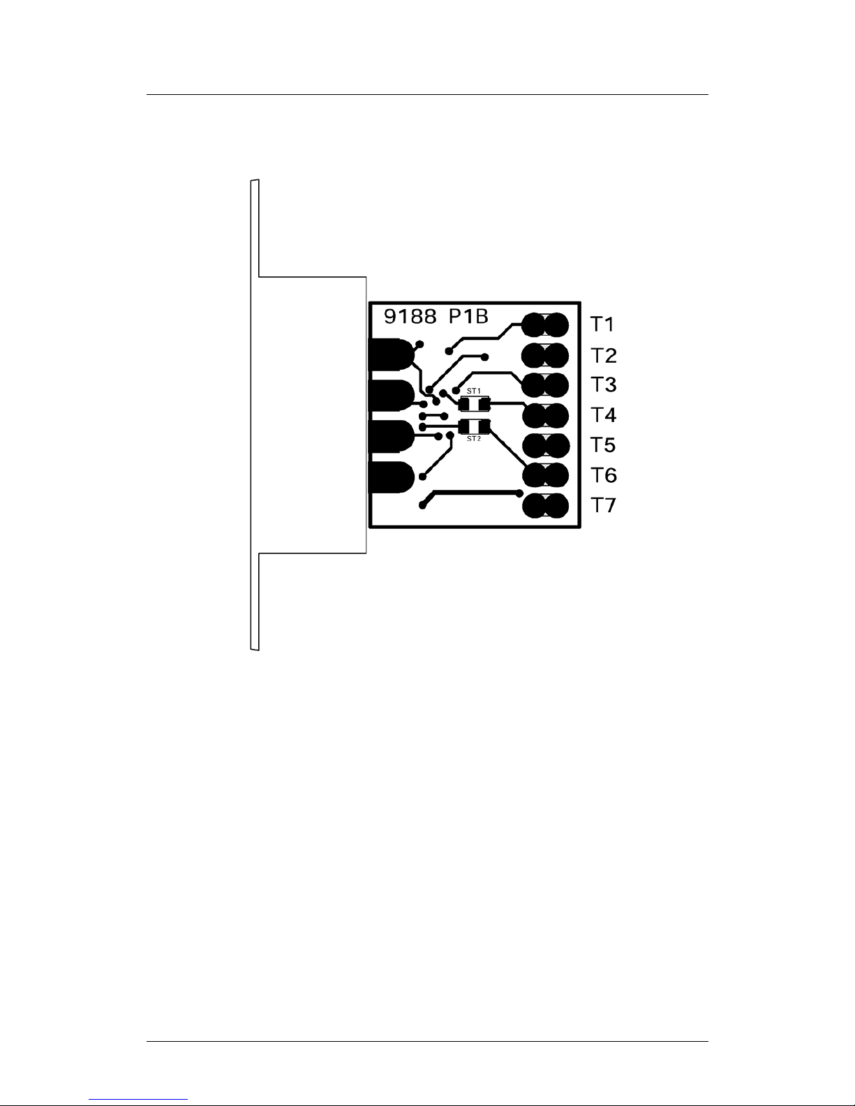
Down the edge of the RS232 PCB, solder terminals T1-T7 are designed to
accept the seven flying leads of the GT47 accessory cable. The other end
of the PCB has a DB9 socket with a DCE pin out. The RS232 PCB uses a
DCE pin out so it can be connected directly to a PC Com Port (DTE) using
a 9-way straight-through modem cable. If the GT47 needs to communicate
with another DCE device use a “Null-Modem” cable between devices.
For a typical assembly, solder each of the 7 flying leads onto the 7 solder
terminals of the level shifter PCB. When not used as part of the RS232
connection scheme, solder terminals T4, T6 and T7 still provide a suitable
anchor point for the flying leads. The second hole for each solder terminal
may be used for extending the wiring by soldering a new length of cable in
series with the original.
Configuration of the design can be either the default, simple 3-wire
interface (RD, TD, GND), or a 5-wire interface (RD, TD, RTS, CTS, GND)
with the addition of two surface mount resistors.
The connections incorporated onto the PCB are listed in table 1.
LZT 123 7698 R1B 5
Page 6
RS232 interface for GT47 embedded apps UART
Table 1 - PCB Connections List
GT47
HD1
5 Pin
Flying
Lead
Colour
PCB
Solder
Termina
l
GT47
Signal
Directio
n
Signa
l
Name
DB9
Socke
t Pin
5
Brown T1
Out RD
2
9
Red T2
Out VDD
-
4
Black T3
In TD
3
12
Yellow T4
Out CTS
8
14
Green T5
- GND
5
11
Orang
e
T6
In RTS
7
15
Blue T7
In‡ -
-
- - - - DCD*
1*
- - - - DTR*
4*
- - - - DSR*
6*
- - - - RI
9
* DB9 signals DCD, DTR and DSR (pins 1, 4 and 6) are
internally shorted together to provide a hardware flow control
loop back to the DTE.
‡
Solder Terminal T7 is provided as a spare. It is designated as
a general purpose input to the GT47 when soldered to the blue
flying lead of the developer’s kit cable (which connects to
HD15 pin 15).
LZT 123 7698 R1B 6
Page 7

RS232 interface for GT47 embedded apps UART
2.2 3-Wire RS232
In the 3-wire configuration, surface mount strap resistors (ST1 and ST2)
are not mounted. Flow control should be disabled on each communicating
device (AT+ IFC)
As the GT47 general purpose outputs each require a resistor pull-up,
these are provided on the RS232 interface PCB. The internal pull-up on
ST1 makes the CTS signal on the DB9 appear as ‘inactive’ state. As long
as flow control is disabled at the DTE this will not cause a problem. If flow
control cannot be disabled at the DTE, the ‘inactive’ state on CTS will
prevent the DTE from communicating. In this case, either solder a single
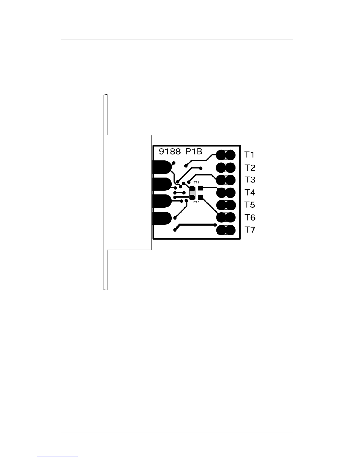
strap resistor between the pads of both ST1 and ST2 as shown in
or enable flow control from the GT47 and add straps ST1 and ST2 (see
section 2.3).
Figure 4
2.3 5-Wire RS232
In the 5-wire configuration, surface mount strap resistors (ST1 and ST2)
must be mounted. This requires soldering 0603-size zero ohm resistors
into positions ST1 and ST2 as indicated in figure 3.
Adding the surface mount resistors should be performed by a skilled
technician and the PCB must first be disconnected from all communicating
devices.
2.4 DCE to DCE (Null-Modem)
If the GT47 UART is to be used as a DTE, instead of the default DCE
configuration, the following changes will be necessary. A 9-way DB9
gender-changer should be used to convert the output from a socket to a
plug. The following DB9 pin connections should be swapped
• Pin-2 swapped with pin-3
• Pin-7 swapped with pin-8.
The pin-swapping can be achieved by using a “Null-Modem” cable
between the DB9 plugs of the communication devices.
LZT 123 7698 R1B 7
Page 8

RS232 interface for GT47 embedded apps UART
2.5 Spare Connections
The spare soldering terminal, T7, is provided to easily lengthen the
connection from the GT47 to the application hardware. The cable
provided in the developer’s kit is a fixed 1 metre length, with tinned-copper
flying leads. In the event of the general purpose input wire length being
too short, an extension wire can be joined using the spare terminal hole in
T7. Terminal T7 is not electrically connected to the RS232 PCB
electronics so signals carried on it will not affect RS232 operation.
LZT 123 7698 R1B 8
Page 9
RS232 interface for GT47 embedded apps UART
3 Assembly Parts
Part Description
PCB RS232 Level Translator PCB
P/N# 9188-P1B
© Sony Ericsson M2M Com
R1, R2 1kΩ (0603)
C1,C2,C3,C4,C5 100nF (0603)
U1 SP3223EEY
X1 DB9 Socket (DCE)
ST1, ST2 0Ω link resistor (0603)
[not mounted]
Back Shell Plastic DB9 Hood
[+ strain relief and screws)
LZT 123 7698 R1B 9
Page 10
RS232 interface for GT47 embedded apps UART
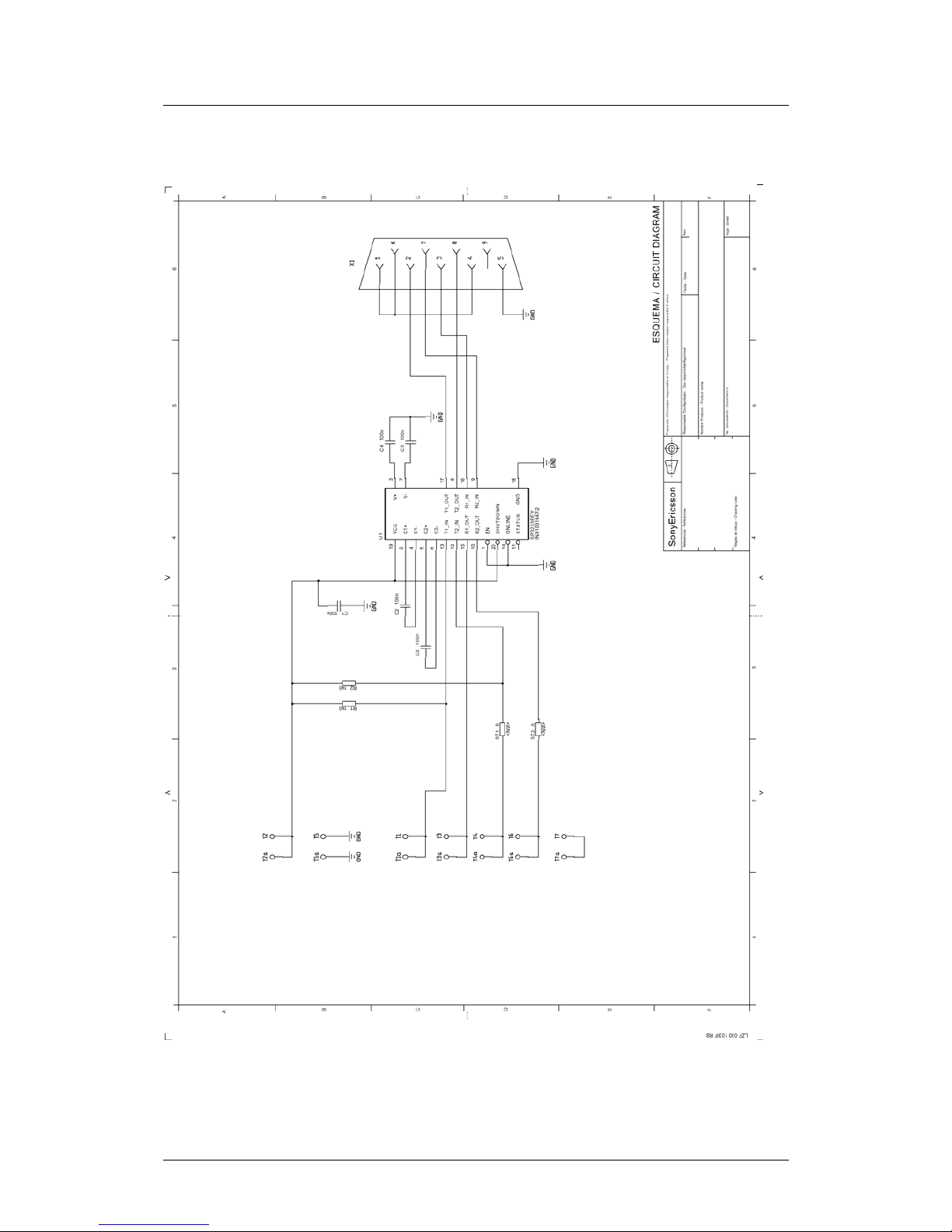
APPENDIX A
Figure 1. RS232 Converter Schematic
LZT 123 7698 R1B 10
Page 11
RS232 interface for GT47 embedded apps UART
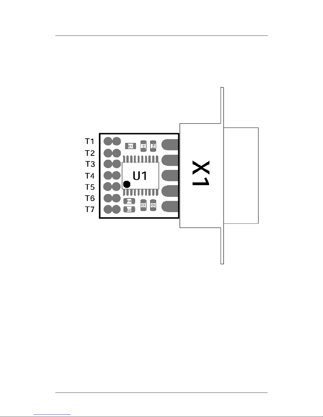
APPENDIX B
Figure 2 - PCB Top Side
LZT 123 7698 R1B 11
Page 12
RS232 interface for GT47 embedded apps UART
Figure 3 - PCB Bottom Side
LZT 123 7698 R1B 12
Page 13
RS232 interface for GT47 embedded apps UART
Figure 4 - RTS/CTS Flow Control Loop back
LZT 123 7698 R1B 13
Page 14
RS232 interface for GT47 embedded apps UART
LZT 123 7698 R1B 14
GLOSSARY
Com Port Serial Communications Port
CTS Clear To Send
DB9 Standard Density 9-pin ‘D’-type Sub-miniature Connector
DCD Data Carrier Detect
DCE Data Communicating Equipment
DSR Data Set Ready
DTE Data Terminating Equipment
DTR Data Terminal Ready
GND Power Supply Ground Connection
GSM Global System for Mobile Communications
HD15 High Density 15-pin ‘D’-type Sub-miniature Connector
PCB Printed Circuit Board
RD Receive Data
RI Ring Indicator
RTS Request To Send
SMS Short message Service
TD Transmit Data
UART Universal Asynchronous Receiver Transmitter
VDD Power Supply Voltage Connection
 Loading...