

Page 1

Installation Instruction, Electrical
Installation Instruction, Electrical
Applicable for F500 and K500 family
Contents
1
Abstract............................................................................................................................2
2 General............................................................................................................................. 2
3 Hardware.........................................................................................................................2
3.1 Test Setup .......................................................................................................... 2
3.1.1 Test Set .............................................................................................................. 3
3.1.2 RF Connections Antenna Coupler.....................................................................3
3.1.3 RF Connections Antenna adapter (optional) .....................................................3
3.2 Test Setup – SERP (only authorized centers).................................................... 3
3.2.1 Test Set .............................................................................................................. 4
3.2.2 Power Supply.....................................................................................................4
3.2.3 GPIB..................................................................................................................4
3.2.4 RF Connection................................................................................................... 4
3.2.5 Flash Interface ...................................................................................................4
3.2.6 Dummy Battery .................................................................................................4
3.3 Computer ........................................................................................................... 4
3.4 Hardlock ............................................................................................................ 5
3.5 Service Card Reader .......................................................................................... 5
3.6 SonyEricsson programming interface – SEPI ...................................................5
3.7 SonyEricsson interface – SEPI ..........................................................................6
3.8 USB PC cable....................................................................................................6
3.9 Label Printer (optional) .....................................................................................6
3.10 Infrared Device ..................................................................................................6
4 Software ........................................................................................................................... 7
4.1 EMMA II...........................................................................................................7
4.2 Labelmake software (optional)..........................................................................7
4.3 Radio script........................................................................................................ 7
4.4 SERP (only authorized centers)......................................................................... 7
5 Revision History ..............................................................................................................8
1/00021-2/FEA 204 544/86 C
Company Internal
Sony Ericsson Mobile Communications AB
Approved according to 000 21-LXE 107 42/1
Page 2
Installation Instruction, Electrical
1 Abstract
This document describes the installation procedure for the Electrical repair package.
2 General
The Electrical repair package consists of a Test Set, an RF Shield box including an antenna
coupler, an RF-antenna adapter (optional), a Computer and Interface cables. A Hardlock and
a Service Card are required for security reasons. A label printer can be installed to make it
possible to print new labels (optional).
3 Hardware
All test hardware must be approved by Sony Ericsson and is documented in the Equipment
and Instrument List.
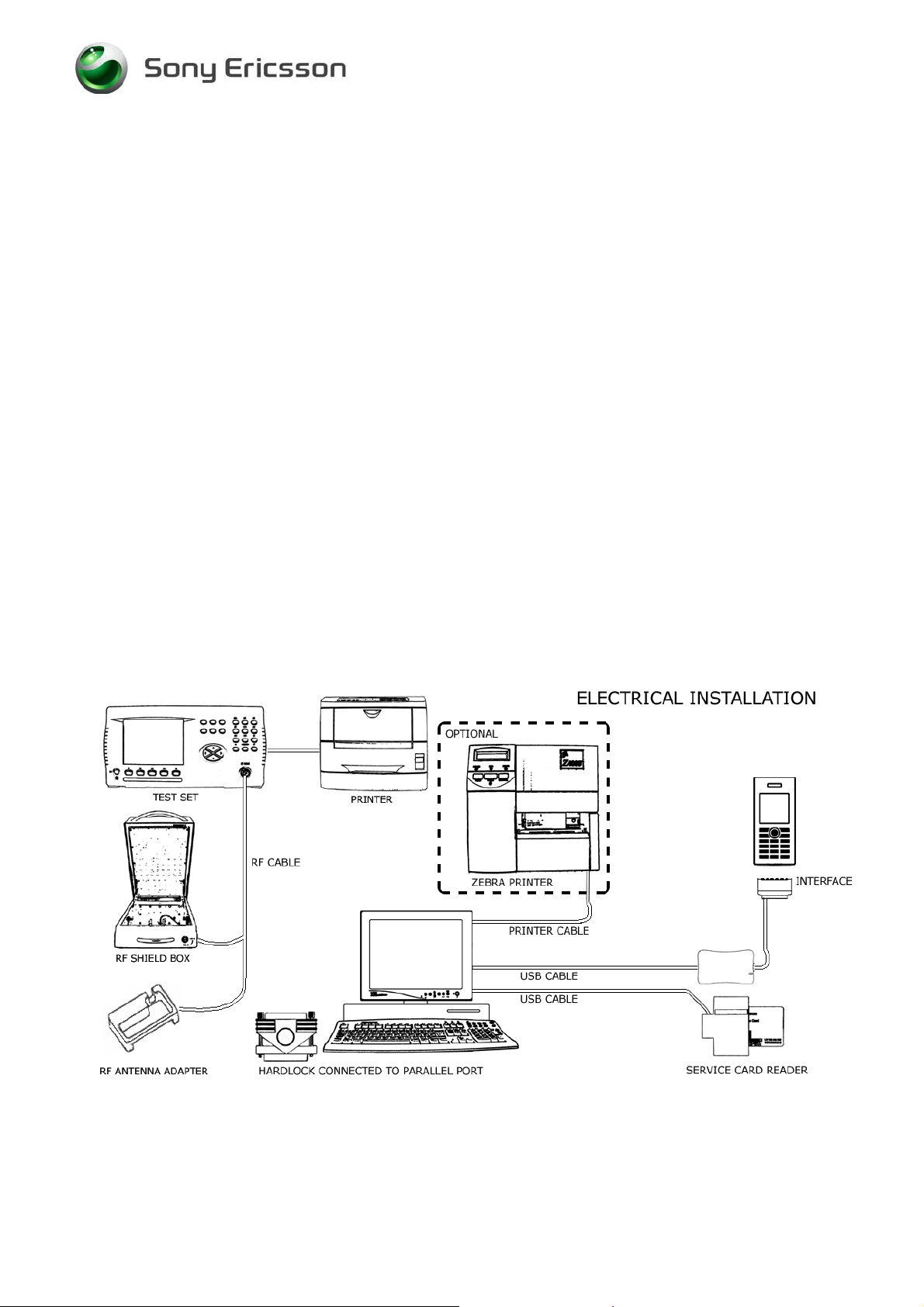
3.1 Test Setup
*The equipment in this picture is specified in the Equipment and Instrument List.
1/00021-2/FEA 204 544/86 C
Company Internal
Sony Ericsson Mobile Communications AB
2(8)
Page 3
Installation Instruction, Electrical
3.1.1 Test Set
An E-GSM 900/GSM 1800/GSM 1900 Test Set approved according to the Instrument List
must be used.
It should be installed according to the Instrument Manufacturer Instructions.
3.1.2 RF Connections Antenna Coupler
Connect the RF Cable between the RF-port of the Test set and the RF Shield box. The
Antenna Coupler should be installed into the RF Shield Box according to the supplied
instructions.
3.1.3 RF Connections Antenna adapter (optional)
Connect the RF-cable between the RF-port of the Test set and the Antenna adapter. Assemble
the antenna adapter to the RF-holder according to the information in the Test instruction
Electrical.
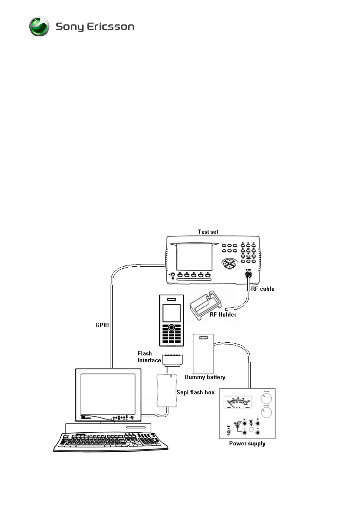
3.2 Test Setup – SERP (only authorized centers)
1/00021-2/FEA 204 544/86 C
Company Internal
Sony Ericsson Mobile Communications AB
3(8)
Page 4

Installation Instruction, Electrical
3.2.1 Test Set
A Test Set approved according to the Instrument List must be used.
It should be installed according to the Instrument Manufacturer Instructions.
3.2.2 Power Supply
Power Supply according to Instrument List must be used.
3.2.3 GPIB
GPIB connection according to Instrument List.
3.2.4 RF Connection
RF-holder and antenna connection according to Equipment List.
3.2.5 Flash Interface
The interface connects the phone to the computer and makes it possible to send and receive
information to the SERP application.
3.2.6 Dummy Battery
Dummy battery according to Equipment List.
3.3 Computer
IBM compatible computer. The computer should include at least two USB-ports. To run all
applications on one computer the minimum system requirement is to run Windows XP.
Emma II and LabelMake requirements are Windows 98 and forward and SERP needs
Windows 2000 or Windows XP installed.
1/00021-2/FEA 204 544/86 C
Company Internal
Sony Ericsson Mobile Communications AB
4(8)
Page 5

Installation Instruction, Electrical
3.4 Hardlock
Hardlock with article number KRY 105 165 is required. The Hardlock should be connected to
the parallel port.
3.5 Service Card Reader
The Service Card Reader is delivered with the necessary software and instructions for
installation. The Service Card Reader should be connected to an USB-port on the computer.
Service Card Service Card Reader
3.6 SonyEricsson programming interface – SEPI
The USB programming interface is delivered with the necessary software and instruction for
installation. The USB programming interface should be connected to an USB-port on the
computer.
1/00021-2/FEA 204 544/86 C
Company Internal
Sony Ericsson Mobile Communications AB
5(8)
Page 6

Installation Instruction, Electrical
3.7 SonyEricsson interface – SEPI
The cable is the interface between the USB programming interface and the phone.
3.8 USB PC cable
The A-B Plug-Plug cable is the interface between the computer and the USB interface.
Connect the cable between the USB programming interface and the computer.
3.9 Label Printer (optional)
A Zebra printer model 90xi, 90xiII or 4000 deluxe shall be used. Connect the printer with a
standard RS 232 serial printer cable [refer to the Zebra printer manual] to the serial port on
the computer. Read the Zebra installation manual for more information about the installation.
3.10 Infrared Device
A Jet-Eye, built in Infrared on laptop or other Infrared device can be used to verify the
Infrared function in the phone. Install the chosen equipment according to the installation
instruction from the manufacture.
1/00021-2/FEA 204 544/86 C
Company Internal
Sony Ericsson Mobile Communications AB
6(8)
Page 7

Installation Instruction, Electrical
4 Software
4.1 EMMA II
EMMA II contains all software required to service the product. Installation and user manuals
are available in the EMMA II start page.
http://emma.extranet.sonyericsson.com
4.2 Labelmake software (optional)
Download the Labelmake software from CSPN. Unzip the file and run the setup.exe and
follow the instructions. Read the file README.txt under C:\Program
Files\Ericsson\Labelmake and follow the instructions. Start the program by selecting
Labelmake in your Windows START-menu.
This product is using labels from the EU-database. To add the latest Database from CSPN
download the latest file and run the Setup.exe and follow the instructions.
http://cspn.extranet.sonyericsson.com
4.3 Radio script
Download the latest radio script file from CSPN / Repair Instructions / Standard. Install the
script file according to the Instrument Manufacturer Instructions.
4.4 SERP (only authorized centers)
Download the latest radio script file from CSPN / Repair Instructions / Standard
,
Install according to manufactures instructions.
1/00021-2/FEA 204 544/86 C
Company Internal
Sony Ericsson Mobile Communications AB
7(8)
Page 8

Installation Instruction, Electrical
5 Revision History
Rev. Date Changes / Comments
A 2004-06-30 Initial release
B 2004-07-13 Revision update due to publishing problems
C 2004-08-19 K500 Added
1/00021-2/FEA 204 544/86 C
Company Internal
Sony Ericsson Mobile Communications AB
8(8)
 Loading...