

Page 1

Working Instruction, Electrical
Working Instruction, Electrical
Applicable for F500 and K500 family
Contents
Lead free soldering .........................................................................................................2
1
2
BGA Equipment reflow profiles (lead free)..................................................................5
2.1
General ..............................................................................................................5
2.2
Temperature measurement ................................................................................ 5
3
BGA Equipment reflow profiles (lead free)..................................................................6
4
BGA Equipment reflow profiles (leaded) .....................................................................7
5
Replacement of parts......................................................................................................8
6
Replacement of parts......................................................................................................9
6.1
Battery connector...............................................................................................9
6.2
Board to board connector ................................................................................10
6.3
FPC connector.................................................................................................11
6.4
Form shield can fence......................................................................................12
6.5
PA shield can...................................................................................................14
6.6
Replacing shield can fence if damage at a repair center..................................14
7
Revision History............................................................................................................15
3/00021-2/FEA 209 544/86 E
Company Internal
©
Sony Ericsson Mobile Communications AB
Approved according to 000 21-LXE 107 42/1
Page 2
Working Instruction, Electrical
1 Lead free soldering
Instruction
Keep all contact surfaces clean of dirt and hand-grease
Step-by-Step Instructions
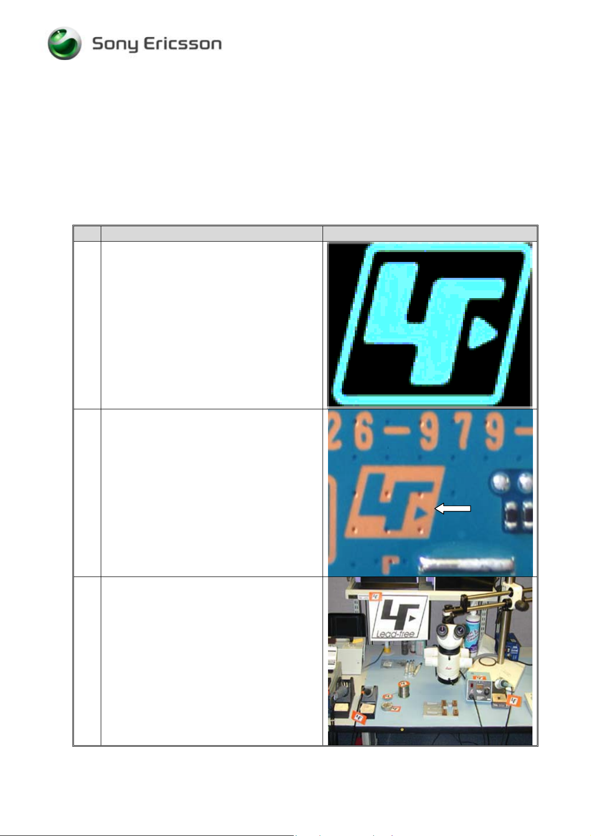
1 NOTE!
This product is manufactured with lead-free
solder and lead-free components.
During electrical repair, it is critical to make
sure that no lead is introduced.
The symbol indicates that the product is lead
free.
2 The first lead free PBA will not be marked with
this LF symbol; they are identified as lead free
by a new revision on the ROA label. All future
PBA is handled lead free
It’s important that from revision:
ROA 128 0768/3 R2A and onwards PBA is
handled with Lead Free process.
3 A lead-free work area must be set up that is
completely separated from work areas that are
used to make leaded repairs.
The lead free work area must also be clearly
labelled with the lead free symbol as shown in
the figure beside.
The items in this table must remain lead free.
They must be adequately labelled to make their
lead-free status clearly and easily recognized.
3/00021-2/FEA 209 544/86 E
Company Internal
©
Sony Ericsson Mobile Communications AB
2(15)
Page 3
Working Instruction, Electrical
Step-by-Step Instructions
4 LFS (Lead free solder paste) characteristics:
High melting point (Typically 220°C)
Low wet ability
High surface tension
Difficult to spread
Recommended tip temperature 370°C
NOTE!
When servicing PBA’s that is produced with
LFS (Lead free solder paste). LFS MUST be
used. If not, there is a high risk for unreliable
soldering joints.
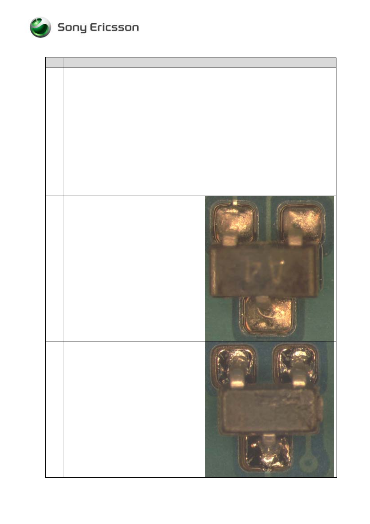
5 Lead-free solder joints are more difficult to
inspect because they do not have shiny surfaces
like leaded solder joints.
Also, lead-free solder does not flow as well as
leaded solder, so some of the solder pad area
may remain exposed.
Example of lead free solders joints.
6 Example of solder joints with lead.
3/00021-2/FEA 209 544/86 E
Company Internal
©
Sony Ericsson Mobile Communications AB
3(15)
Page 4
Working Instruction, Electrical
Step-by-Step Instructions
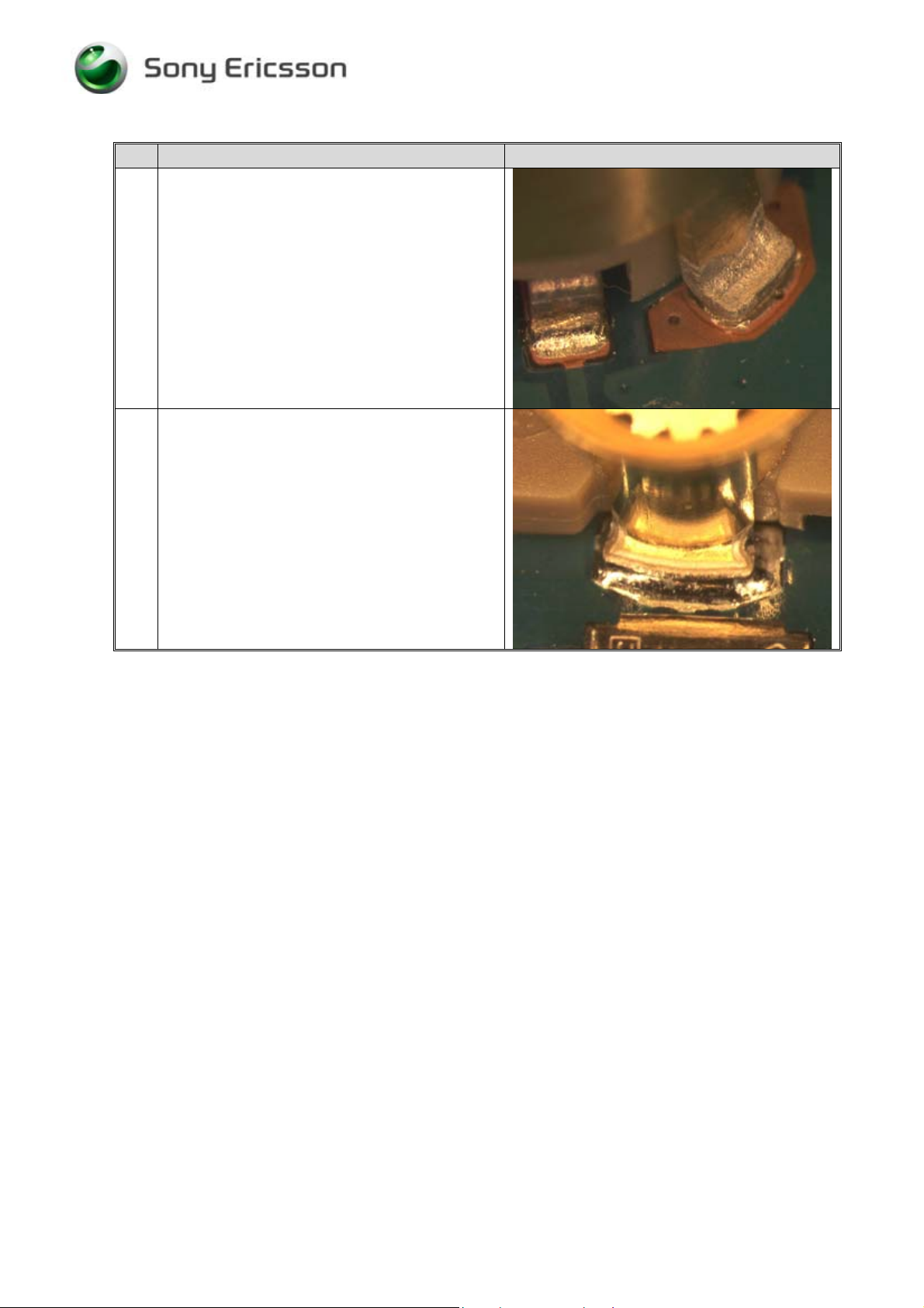
7 Example of lead free solders joints.
8 Example of solder joints with lead.
3/00021-2/FEA 209 544/86 E
Company Internal
©
Sony Ericsson Mobile Communications AB
4(15)
Page 5

Working Instruction, Electrical
2 BGA Equipment reflow profiles (lead free)
2.1 General
This document contains recommendations for reflow profile for mobile phones and similar
products. This is only general recommendation and considerations have to be taken for every
single product. The solder paste is secondary but could also affect the parameters.
In this document one alloy is specified:
SnAgCu (Lead free) melting point 217°C
2.2 Temperature measurement
At least 4 probes should be used; they should be placed on components with the highest and
lowest thermal mass.
The probes shall be located in the beginning, in the middle and at the end of the board/panel.
The probes are recommended to be soldered on the board but glue and capton tape could also
be used if necessary.
At least one probe shall be placed in the air or on top of a component.
These values are strongly depending on the BGA replacement equipment.
Nozzle type will be chosen after the outer size of the actual component. Make sure the nozzle
does not affect any near placed components.
NOTE:
These values are recommendations and may have to be changed depending on the type of
equipment.
The maximum temperature for any component must not exceed 250C.
3/00021-2/FEA 209 544/86 E
Company Internal
©
Sony Ericsson Mobile Communications AB
5(15)
Page 6

Working Instruction, Electrical
3 BGA Equipment reflow profiles (lead free)
These values are strongly depending on the BGA replacement equipment.
Nozzle type will be chosen after the outer size of the actual component. Make sure the nozzle
does not affect any near placed components.
NOTE:
These values are recommendations and may have to be changed depending on the type of
equipment.
Sn/Ag/Cu (Lead free)
290
250
Preheat zone
Reflow zone
Cooling zone
260°C
245°C
235°C
200
150
Temperature [ºC]
100
50
0
40 80 120 160 200 240 280
Time [Seconds]
Ramp rate < 4°C/sec
Ramp rate cooling zone < 6°C/sec
Time above liquidus 60-150 sec
Minimum temperature 235°C
Maximum temperature 245°C or 260°C* for 10 sec
Total time Appr. 4-7 min
• The higher temperature in case the board has extremely high ∆T.
3/00021-2/FEA 209 544/86 E
Company Internal
©
Sony Ericsson Mobile Communications AB
6(15)
Page 7

Working Instruction, Electrical
4 BGA Equipment reflow profiles (leaded)
These values are strongly depending on the BGA replacement equipment.
Nozzle type will be chosen after the outer size of the actual component. Make sure the nozzle
does not affect any near placed components.
NOTE:
These values are recommendations and may have to be changed depending on the type of
equipment.
General reflow profile sn/pb (leaded)
Preheat zone
250
200
150
Temperature [ºC]
10
0
50
0
040 80120 160 200 240 280
Time [Seconds]
Reflow
zone
Cooling
zone
Ramp rate < 3°C/sec
Ramp rate cooling zone < 6°C/sec
Time above liquidus 60-150 sec
Minimum temperature 215°C
Maximum temperature 225°C or 235°C for 10-20 sec
Total time Appr. 4-7 min
*
3/00021-2/FEA 209 544/86 E
Company Internal
©
Sony Ericsson Mobile Communications AB
The higher temperature in case the board has extremely high ∆T.
7(15)
Page 8

Working Instruction, Electrical
5 Replacement of parts
• Equipment
• Dentist hook
• ESD-gloves (cotton gloves)
• ESD-wristband
• Soldering tool
• Hot air soldering station
• BGA replacement equipment
• Pair of tweezers
• Solder cleaning wiper (Tin wick)
• Solder paste, for Lead free use (SN 96% Ag 3.5% Cu 0.5%)
• Flux, RMA No-clean flux
• Cutting pliers
• Shield fence pliers NTZ 112 537
Instruction
• Keep all contact surfaces clean of dirt and hand-grease
3/00021-2/FEA 209 544/86 E
Company Internal
©
Sony Ericsson Mobile Communications AB
8(15)
Page 9

Working Instruction, Electrical
6 Replacement of parts
6.1 Battery connector
Process tools
• BGA replacement equipment
• Pair of tweezers
• Solder cleaning wiper (Tin wick)
• Solder paste
• Gel flux
Equipment
• ESD-gloves (cotton gloves)
• ESD-wristband
Instruction
• Disassemble the phone as described in Working Instruction 3/00021-1/FEA 209 544/86
Step-by-Step Instructions
1 Replace the component.
Use BGA repair equipment.
No special treatment due to through pins.
• Reassemble the phone as described in Working Instruction 3/00021-1/FEA 209 544/86
3/00021-2/FEA 209 544/86 E
Company Internal
©
Sony Ericsson Mobile Communications AB
9(15)
Page 10
Working Instruction, Electrical
6.2 Board to board connector
Process tools
• BGA replacement equipment
• Pair of tweezers
• Solder cleaning wiper (Tin wick)
• Solder paste
• Gel flux
Equipment
• ESD-gloves (cotton gloves)
• ESD-wristband
Instruction
• Disassemble the phone as described in Working Instruction 3/00021-1/FEA 209 544/86
Step-by-Step Instructions
1 Replace the component.
Use BGA repair equipment.
After soldering check for solder bridges between
solder joints.
• Reassemble the phone as described in Working Instruction 3/00021-1/FEA 209 544/86
3/00021-2/FEA 209 544/86 E
Company Internal
©
Sony Ericsson Mobile Communications AB
10(15)
Page 11

Working Instruction, Electrical
6.3 FPC connector
Process tools
• Dentist hook
• BGA replacement
• Pair of tweezers
• Solder cleaning wiper (Tin wick)
• Solder paste
• Gel flux
Equipment
• ESD-gloves (cotton gloves)
• ESD-wristband
Instruction
• Disassemble the phone as described in Working Instruction 3/00021-1/FEA 209 544/86
Step-by-Step Instructions
1 Replace the component.
Use BGA repair equipment.
After soldering check for solder bridges between
solder joints.
• Reassemble the phone as described in Working Instruction 3/00021-1/FEA 209 544/86
3/00021-2/FEA 209 544/86 E
Company Internal
©
Sony Ericsson Mobile Communications AB
11(15)
Page 12

Working Instruction, Electrical
6.4 Form shield can fence
Process tools
• Dentist hook
• Cutting pliers
• Shield fence pliers NTZ 112 537
Equipment
• ESD-gloves (cotton gloves)
• ESD-wristband
Instruction
• Disassemble the phone as described in Working Instruction 3/00021-1/FEA 209 544/86
3/00021-2/FEA 209 544/86 E
Company Internal
©
Sony Ericsson Mobile Communications AB
12(15)
Page 13

Working Instruction, Electrical
Step-by-Step Instructions
1 Remove the shield can lid.
If needed it is allowed to remove the pick up
area with a cutting pliers (1). This pick up area is
only used when machine mounting the can and
there is no need to put it back again.
NOTE!
Assure that the cutting pliers is sharp-edged to
prevent damaging the shield can fence.
Cut the fence according to the red lines in the
picture.
Form the frame carefully without bending the
shield can fence wall. Use Shield fence pliers
NTZ 112 537.
Replace the component and gently fold back the
fence. Be very cautious with the shield can fence
wall.
Put back a new shield can lid. Press on all sides
of the lid until you hear a “click” sound.
• Reassemble the phone as described in Working Instruction 3/00021-1/FEA 209 544/86
3/00021-2/FEA 209 544/86 E
Company Internal
©
Sony Ericsson Mobile Communications AB
13(15)
Page 14

Working Instruction, Electrical
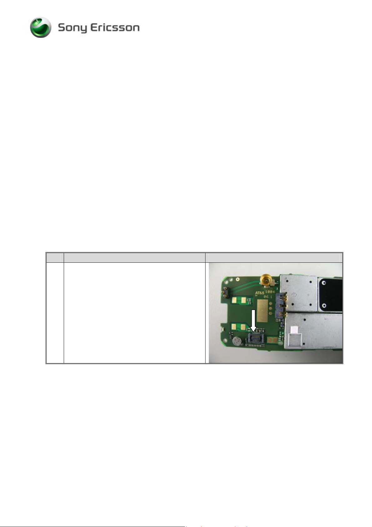
6.5 PA shield can
Instruction
• Disassemble the phone as described in Working Instruction 3/00021-1/FEA 209 544/83
Step-by-Step Instructions
1 NOTE!
This operation is very time consuming and must
be performed by very skilled repair operators.
1) Remove the battery connector X2600 (1)
using hot air
2) Remove the shield can S0102 (2) using
BGA repair equipment or hot air
(temperature profile for lead-free
soldering)
3) Rework the components inside the shield
can
4) Clean pad and add solder
5) Replace the shield can using BGA repair
equipment with a suited nozzle
6)
Replace the battery connector using a
BGA repair equipment
• Reassemble the phone as described in Working Instruction 3/00021-1/FEA 209 544/83
6.6 Replacing shield can fence if damage at a repair center
Process tools
• Dentist hook
• BGA repair equipment
• Hot air soldering station
• Pair of tweezers
• Solder cleaning wiper (Tin wick)
• Solder paste
• Solder wire
• Gel flux
• Cutting pliers
Equipment
• ESD-gloves (cotton gloves)
• ESD-wristband
3/00021-2/FEA 209 544/86 E
Company Internal
©
Sony Ericsson Mobile Communications AB
14(15)
Page 15

Working Instruction, Electrical
Instruction
• Disassemble the phone as described in Working Instruction 3/00021-1/FEA 209 544/86
Step-by-Step Instructions
1 NOTE!
Replacing shield can fence is only done at repair
centers when a shield can fence is damaged after
bending the frame.
This operation is very time consuming and must
be performed by very skilled repair operators.
Remove the shield can fence by using hot air (or
preferrably with BGA repair equipment).
Most often it is necessary to remove the shield
can fence in pieces by using cutting pliers.
Assemble a new shield can fence with BGA
repair equipment.
• Reassemble the phone as described in Working Instruction 3/00021-1/FEA 209 544/86
7 Revision History
Rev. Date Changes / Comments
A 2004-06-30 Initial release
B 2004-07-13 Revision update due to publishing problems
C 2004-08-19 K500 Added
D 2004-12-21 Lead Free information added
E 2005-07-13 Corrected fields, added instructions for Shielding Can PA SXA
109 5603
3/00021-2/FEA 209 544/86 E
Company Internal
©
Sony Ericsson Mobile Communications AB
15(15)
 Loading...