

Page 1
Test Instruction, Electrical
Test Instruction, Electrical
Applicable for F500 and K500 family
Contents
General............................................................................................................................. 2
1
2 Test Procedure ................................................................................................................2
3 Test flow...........................................................................................................................2
3.1 Software Update ................................................................................................ 2
3.1.1 Verify Software Version....................................................................................2
3.1.2 Update Software Version ..................................................................................2
3.2 Go/No-Go Test ..................................................................................................3
3.3 Service Tests...................................................................................................... 4
3.3.1 Main Display Test .............................................................................................4
3.3.2 Camera Test....................................................................................................... 4
3.3.3 LED/Illumination Test.......................................................................................4
3.3.4 Keyboard Test ...................................................................................................5
3.3.5 Vibrator Test...................................................................................................... 5
3.3.6 Earphone Test....................................................................................................5
3.3.7 Speaker Test ......................................................................................................5
3.3.8 Microphone Test................................................................................................ 6
3.3.9 Real Time Clock Test........................................................................................6
3.4 Manual Tests .....................................................................................................6
3.4.1 On The Air Call to Mobile ................................................................................6
3.4.2 Infrared Test ......................................................................................................6
3.4.3 System Connector Test......................................................................................7
4 Revision History ..............................................................................................................8
2/00021-2/FEA 209 544/86 C
Company Internal
Sony Ericsson Mobile Communications AB
Approved according to 000 21-LXE 107 42/1
Page 2
Test Instruction, Electrical
1 General
This document describes the test procedure for the Electrical repair package.
2 Test Procedure
To verify all components within the Electrical repair package, all tests must be performed.
3 Test flow
If the phone is passing these steps of testing without any failures,
it is OK to return it to the customer.
If there are any failures, repair the phone according to the troubleshooting guide.
3.1 Software Update
Update to latest phone signalling software from EMMA II.
3.1.1 Verify Software Version
To verify if the phone needs new software, you have to check the Software Version in the
phone. Current Software Versions are checked through the following steps:
1. Start up the phone.
2. Press the following navigation-key and keyboard sequence: !!""!"!
3. Select Service info.
4. Select SW Information.
5. Check the file revisions on the display.
6. Press OK to return to the Service info menu.
3.1.2 Update Software Version
Update the software in the phone by doing the following steps:
1. Make sure that the phone’s battery is fully charged or use a Dummy battery. Connect
correct flash cable and interface according to the Installation instruction.
2. Connect to the EMMA II server, choose application "GSM" and follow the instructions.
2/00021-2/FEA 209 544/86 C
Company Internal
Sony Ericsson Mobile Communications AB
2(8)
Page 3
Test Instruction, Electrical
3.2 Go/No-Go Test
This test verifies that the radio parameters of the phone fulfil the EGSM900/GSM
1800/GSM1900 specification. If all measurements are approved, this will be confirmed. If
any faults are discovered, this will be presented either on the screen or printed out. It’s
possible to do this test either with antenna coupler from Rohde&Schwarz or RF adapter.
When using RF adapter a dummy battery shall be used.
It’s very important that a fully charged battery is used otherwise there is a risk for wrong test
results.
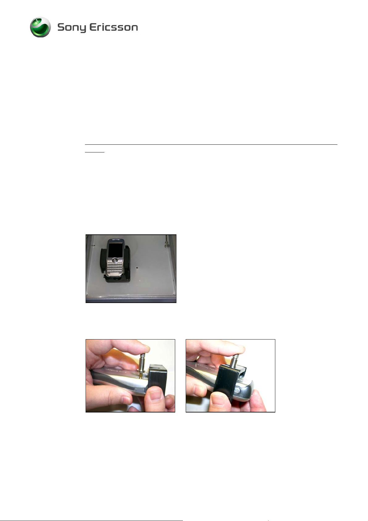
Antenna Coupler
• Insert a test-SIM and a fully charged standard battery. Position the phone in the coupler
according to the picture (Fig 1).
RF adapter
• Insert a test-SIM and a dummy battery. Assemble the RF adapter according to Fig 2 and
2.1. Connect the RF cable RPM 119 855 between the Test set and the antenna adapter.
Fig. 1 Position of the phone in to
the Antenna holder.
Fig.2 Press the antenna connector gently
against the external antenna connector
2/00021-2/FEA 209 544/86 C
Company Internal
Sony Ericsson Mobile Communications AB
Fig.2.1 Slide the holder towards the RFconnector until the adapter is in place. The
RF adapter should be placed into the slot
“B” on the holder.
3(8)
Page 4

Test Instruction, Electrical
1. Start the Test set, and run the script called “F500”.
2. Follow the instructions on the Test instrument during the test.
3.3 Service Tests
NOTE! It is not necessary to have a SIM card inserted.
Start the phone.
The Service Tests menu is entered using the following navigation-key and key sequence:
!!""!"! and select “Service Tests”.
3.3.1 Main Display Test
To verify the display:
1. Select “Main Display” from the “Service Tests” menu.
2. The display toggles between four different test patterns.
Make sure that there are no dots missing and that the colours and contrast is OK.
3. Press the “#” key to go back to the service tests menu.
3.3.2 Camera Test
To verify the camera functionality:
1. Select “Camera” from the “Service Tests” menu.
2. The camera function will now starts and are visible in the display. Make sure that the
contrast and light is OK.
3. Press the “#” key to go back to the service tests menu.
3.3.3 LED/Illumination Test
To verify that the backlight and the Top LED is OK:
1. Select “LED/illumination” from the “Service Tests” menu.
2. Check that the backlight on the LCD and the keyboard is toggle between on and off.
3. Check also that the red led in the On/Off key is toggle between on end off.
4. Press the “Ok” key to go back to the service tests menu.
2/00021-2/FEA 209 544/86 C
Company Internal
Sony Ericsson Mobile Communications AB
4(8)
Page 5

Test Instruction, Electrical
3.3.4 Keyboard Test
To verify that the keyboard, the navigation-key and the volume key are OK:
1. Select “Keyboard” from the “Service Tests”.
2. Press all keys on the keypad, the camera key and the volume keys on the left side and the
“Web” key on the right side. If they are ok, a text feedback is displayed showing the
information which key was pressed. All keys should be tested. On/Off key is included in
the test.
3. If you stop pressing keys the phone will return to the service test menu after 3 seconds.
3.3.5 Vibrator Test
To verify the vibrator function:
1. Select “Vibrator” from the “Service Tests” menu.
2. Press any key and the vibrator will vibrate 3 times.
3. Press the “Ok” key to go back to the service tests menu.
3.3.6 Earphone Test
To verify the Earphone function:
1. Select “Earphone” from the “Service Tests” menu.
2. Adjust the volume with the joystick and make sure that the Earphone is working properly.
3. Press the “Ok” key to go back to the service tests menu.
3.3.7 Speaker Test
To verify the Speaker function:
1. Select “Speaker” from the “Service Tests” menu.
2. Adjust the volume with the joystick and make sure that the Speaker is working properly.
3. Press the “Ok” key to go back to the service tests menu.
2/00021-2/FEA 209 544/86 C
Company Internal
Sony Ericsson Mobile Communications AB
5(8)
Page 6

Test Instruction, Electrical
3.3.8 Microphone Test
This test is intended to test the microphone. Therefore, the earphone should be tested before
this test is entered.
1. Select “Microphone” from the “Service Tests” menu.
2. The phone will start to record and after that the sound is played in the speaker. Make sure
that the record sounds have a load and clear sound.
3. Press the “Ok” key to go back to the service tests menu.
3.3.9 Real Time Clock Test
This test will check if the built in real time clock works.
1. Select “Real time clock” from the “Service Tests” menu.
After approximately 5 seconds you will get information whether the clock is ok or not.
2. Press the “#” key to go back to the service tests menu.
3.4 Manual Tests
3.4.1 On The Air Call to Mobile
To verify the function of the speaker, microphone, polyphonic ring signal, volumes button
and radio:
1. Insert an operator SIM card and start the phone.
2. Set up a call from another phone to the mobile phone.
3. Answer the phone call.
4. Check that the polyphonic ring signal is working and that the backlight switches on OK.
5. Also check that the quality of the sound both in the mobile phone and the other phone are
OK.
6. Press the volume key up and down and check that the volume in the phone is altered.
7. End the call.
8. Check that the ending procedure is OK and that the speech time is displayed.
3.4.2 Infrared Test
To verify that the Infrared communication is working:
1. Insert a SIM card, connect a battery and start the unit.
2. Activate the function by entering Connectivity/Infrared port and select “10 minutes”.
3. Set up an infrared link between an IR device and the phone. The IR-module is placed on
the right side of the phone. If a link can be established, the module is considered working.
2/00021-2/FEA 209 544/86 C
Company Internal
Sony Ericsson Mobile Communications AB
6(8)
Page 7

Test Instruction, Electrical
3.4.3 System Connector Test
Hands free equipment and a charger are used in this test, to check the functionality of the
System Connector.
1. Insert a SIM card, connect a battery and start the unit.
2. Connect the Hands free equipment to the system connector and set up a call and listen if
you can speak/hear in the hands free set.
3. Connect the charger to the system connector and see if the phone starts to charge and if
the charging is indicated in the display.
2/00021-2/FEA 209 544/86 C
Company Internal
Sony Ericsson Mobile Communications AB
7(8)
Page 8

Test Instruction, Electrical
4 Revision History
Rev. Date Changes / Comments
A 2004-06-30 Initial release
B 2004-07-13 Revision update due to publishing problems
C 2004-08-19 K500 Added
2/00021-2/FEA 209 544/86 C
Company Internal
Sony Ericsson Mobile Communications AB
8(8)
 Loading...