

Page 1
Installation Instruction, Electrical
Installation Instruction, Electrical
Applicable for K330
Contents
1
General...............................................................................................................2
2 Go/No Go Testing..............................................................................................2
2.1 Test Set-Up Go/No Go test...................................................................2
2.2 Test Set.................................................................................................3
2.3 RF Connections Antenna Coupler.........................................................3
2.4 RF Connections Test Fixture (optional).................................................3
3 Software Loading..............................................................................................4
3.1 Set up....................................................................................................4
3.2 Computer...............................................................................................4
3.3 USB Activation Dongle..........................................................................4
3.4 Sony Ericsson programming interface – DCU-65 .................................4
4 Software............................................................................................................. 5
4.1 EMMA....................................................................................................5
4.2 Labelmake II software (optional)...........................................................5
4.3 SERP Go/No Go Test Script.................................................................5
4.4 SERP Calibration (only authorized centers)..........................................5
4.5 Willtek 420x Go/No-Go Test Script ....................................................... 6
5 Lead-Free Electrical Repair..............................................................................6
6 Revision History................................................................................................8
1219-0635 Rev 1
Company Internal © Sony Ericsson Mobile Communications AB
Page 2
Installation Instruction, Electrical
1 General
The Electrical Installation Instructions describes the procedures for installing all of the
hardware and software needed to perform testing, software loading and repair
activities at an Electrical level for the Sony Ericsson products specified.
2 Go/No Go Testing
There are two options for performing a Go No/Go test. One is to use an RF Fixture
and the other is to use an antenna coupler together with a shielding box.
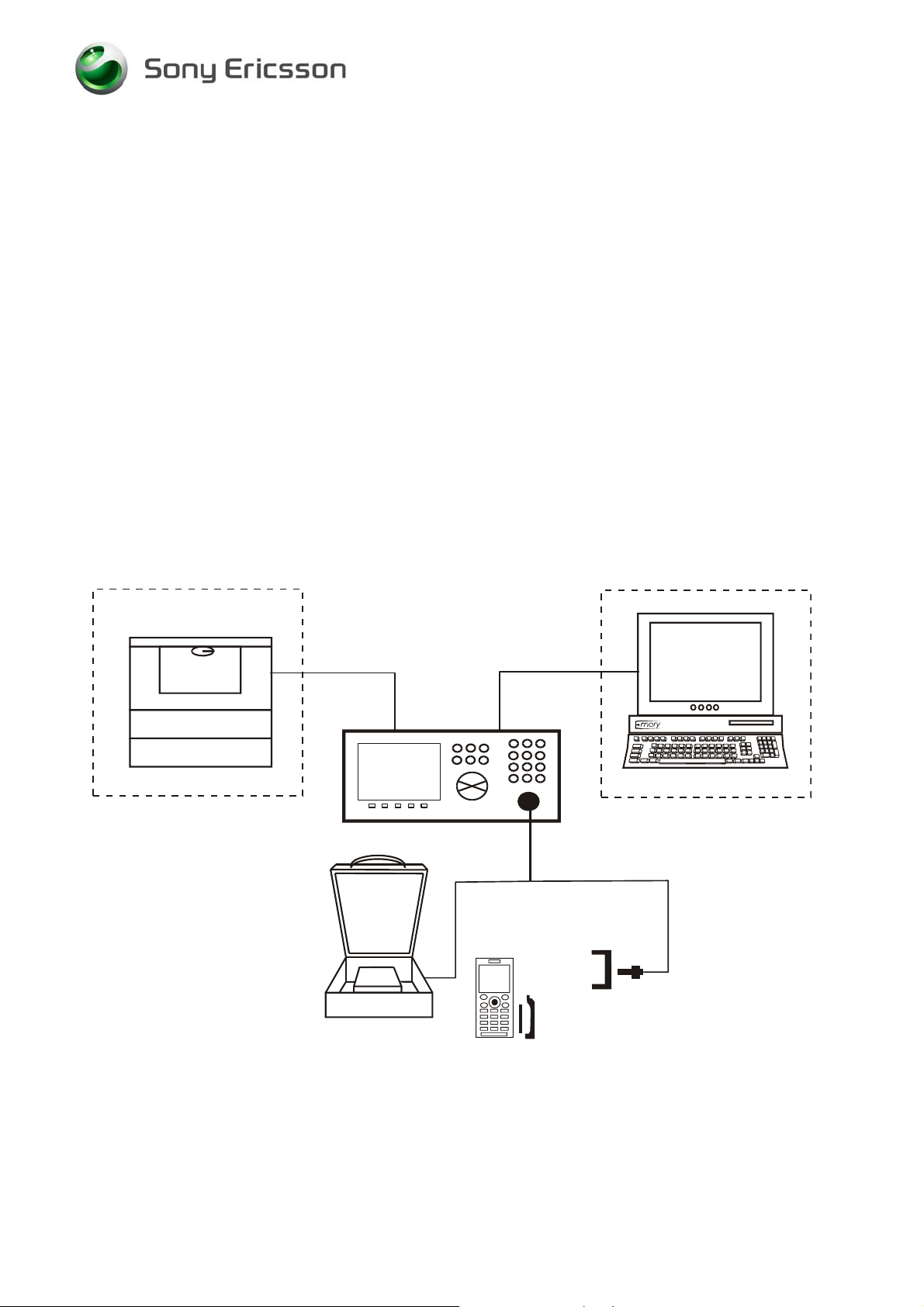
2.1 Test Set-Up Go/No Go test
All test hardware necessary for this test set up is documented in the Mechanical or
Electrical Equipment Lists.
PRINTER
OPTIONAL
Use d fo r
Radiated Signal
to the Unit
TEST SET
RF C ABLE
GPIB
CABLE
RF PRO BE
HOLDER
COMPUTER
OPTIONAL
Used for
Conducted Signal
*
to the Unit
RF SHIELD
BOX
The RF Probe Holder and the Battery Cover may not be used for every product.
See the Installation Instructions and Test Instructions for details.
*
1219-0635 Rev 1
Company Internal © Sony Ericsson Mobile Communications AB
BATTERY AND
BATTERY COVER
RF PROBE
*
2(8)
Page 3
Installation Instruction, Electrical
2.2 Test Set
A 900/GSM, 1800/GSM, 1900/GSM and Test Set approved according to the
Instrument List must be used for K330, K330a & K330c
It should be installed according to the Instrument Manufacturer Instructions.
2.3 RF Connections Antenna Coupler
Connect the RF Cable between the RF-port of the Test set and the RF Shield box.
The Antenna Coupler should be installed into the RF Shield Box according to
manufacturer instructions.
2.4 RF Connections Test Fixture (optional)
Connect the RF-cable between the RF-port of the Test set and the RF Probe.
Assemble the RF Probe to the RF-holder according to the information in the Test
Instruction Electrical.
1219-0635 Rev 1
Company Internal © Sony Ericsson Mobile Communications AB
3(8)
Page 4

Installation Instruction, Electrical
3 Software Loading
3.1 Set up
General Test set up to perform SW loading. All necessary hardware for this test set
up is documented in the Mechanical or Electrical Equipment list.
USB
ACTIVA TION
DONGL E
DCU -65
CABLE
3.2 Computer
IBM compatible computer is required. The computer should include at least three
USB-ports, if the computer has a Card Reader built in only two USB-ports are
required. Refer to Equipment List for minimum requirements.
3.3 USB Activation Dongle
A USB Activation Dongle is required for activation in EMMA. Refer to the EMMA
Homepage available from CSPN, for installation instructions.
3.4 Sony Ericsson programming interface – DCU-65
The cable is the interface between the computer and the phone. DCU-65 cable
should be connected to an USB-port on the computer.
1219-0635 Rev 1
Company Internal © Sony Ericsson Mobile Communications AB
4(8)
Page 5

Installation Instruction, Electrical
4 Software
4.1 EMMA
EMMA contains all software required to service the product. Installation and user
manuals are available in the EMMA start page.
http://ma3.extranet.sonyericsson.com/ma3/
4.2 Labelmake II software (optional)
Label Make II is an application installed through Java Web Start.
Access the Labelmake software from
You will find Label Make II in the dropdown menu on the CSPN web page.
http://cspn.extranet.sonyericsson.com
Press “START Label Make II “button and you will be directed to the LABELMAKE II
client page.
Product labels are downloaded on-line from a remote server database.
CSPN Web page.
4.3 SERP Go/No Go Test Script
SERP stands for “Sony Ericsson Repair Platform”. It is an application used for
testing, calibrating and repairing Sony Ericsson mobile phones.
1. Download the latest revision of the SERP application from CSPN (Repair
Instructions/Standard/SERP Install Package).
2. Unzip the file and open the file “Release Notes and Installation Guide” for
installation instructions.
3. After SERP is installed a file titled “SERPINFO.htm” will be placed on the
Windows Desktop. This file contains numerous documents including:
• SERP Users Manual – This document contains detailed operating and fault
reporting instructions.
• R&S Grid plate for SERP – This document contains an overview and ordering
information for the Rhode & Schwarz Grid Plate used with the Rhode &
Schwarz coupler. Also there is a list of supported SEMC handsets and
mounting positions.
• SERP Release Notes and Installation Guide – This document contains
system requirements, release notes and an Installation Guide
4.4 SERP Calibration (only authorized centers)
Download the latest revision of SERP application from CSPN. This application is
located under
http://cspn.extranet.sonyericsson.com
1. Unzip the file and open the Installation instructions.
2. Follow the Install instructions to install SERP.
1219-0635 Rev 1
Company Internal © Sony Ericsson Mobile Communications AB
Repair Instructions/Standard/SERP Install package
5(8)
Page 6

Installation Instruction, Electrical
4.5 Willtek 420x Go/No-Go Test Script
An approved Sony Ericsson Test Script must be installed in the Test Instrument. The
Willtek 420x script can be downloaded from CSPN. The Test Script is located on
CSPN under Repair Instructions / Standard.
The FEA number for the 420x test script is 1211-9597 x when using the R&S Coupler
or the RF Fixture.
NOTE! The “x” in the FEA number refers to the revision of the Test Script.
Ensure the latest revision script posted to CSPN is installed.
Install the Test Script according to the Instrument Manufacturer’s Instructions.
5 Lead-Free Electrical Repair
This product is manufactured with lead-free solder and lead-free components.
During electrical repair, it is critical to make sure that no lead is introduced into the
product. For this reason, certain repair materials and equipment must be designated
as lead-free and labelled accordingly. A lead-free work area must be setup that is
completely separated from work areas that are used to make leaded repairs. The
lead-free work area must also be clearly labelled as shown in the figure below.
Certain items must be designated for lead-free work only. Some of the items that
need to be clearly labelled in this way are listed in the table below. Note that any item
that contacts the solder must be labelled and used for lead-free work only.
Soldering Tips Wicking Tape Tip Cleaner (steel wool)
Solder Tip Tinner Soldering Iron
1219-0635 Rev 1
Company Internal © Sony Ericsson Mobile Communications AB
6(8)
Page 7

Installation Instruction, Electrical
Because of cost and space limitations, some repair centres may not be able to
assign a full bench to lead-free repairs. In this case, both lead-free and leaded repair
setups can share the same bench, but they must be clearly marked with signs and
separated by a physical divider. In the figure below, the large hot air device functions
as the divider.
1219-0635 Rev 1
Company Internal © Sony Ericsson Mobile Communications AB
7(8)
Page 8
Installation Instruction, Electrical
6 Revision History
Rev. Date Changes / Comments
1 2008-09-25 1st release
1219-0635 Rev 1
Company Internal © Sony Ericsson Mobile Communications AB
8(8)
 Loading...