

Page 1

Go/No Go Test Script Specification, Electrical
Go/No Go Test Script Specification,
Electrical
Applicable for: K330 and K330a
Contents
1
General ...........................................................................................................................3
1.1 About This Document.....................................................................................3
1.2 Script Requirements.......................................................................................3
1.3 Traffic Channel (TCH) Allocation Table ......................................................4
1.4 Power Level Allocation Table........................................................................4
1.5 Test Limits........................................................................................................4
1.6 Attenuation Factors ........................................................................................4
2 K330 Test Sequence - Radiated...............................................................................5
2.1 Initializing and Call Setup..............................................................................5
2.2 Audio Loopback..............................................................................................7
2.3 GSM 900 Low TCH Measurements.............................................................7
2.4 GSM 900 Mid TCH Measurements..............................................................7
2.5 GSM 900 High TCH Measurements............................................................8
2.6 GSM 1800 Low TCH Measurements...........................................................8
2.7 GSM 1800 Mid TCH Measurements............................................................8
2.8 GSM 1800 High TCH Measurements..........................................................9
3 K330 Test Sequence - Conducted.........................................................................10
3.1 Initializing and Call Setup............................................................................10
3.2 Audio Loopback............................................................................................11
3.3 GSM 1800 Low TCH Measurements.........................................................11
3.4 GSM 1800 Mid TCH Measurements..........................................................11
3.5 GSM 1800 High TCH Measurements........................................................12
3.6 GSM 900 Low TCH Measurements...........................................................12
3.7 GSM 900 Mid TCH Measurements............................................................12
3.8 GSM 900 High TCH Measurements..........................................................13
4 K330a Test Sequence - Radiated...........................................................................14
4.1 Initializing and Call Setup............................................................................14
4.2 Audio Loopback............................................................................................16
4.3 GSM 850 Low TCH Measurements...........................................................16
4.4 GSM 850 Mid TCH Measurements............................................................16
4.5 GSM 850 High TCH Measurements..........................................................16
4.6 GSM 1900 Low TCH Measurements.........................................................17
4.7 GSM 1900 Mid TCH Measurements..........................................................17
4.8 GSM 1900 High TCH Measurements........................................................17
5 K330a Test Sequence - Conducted.......................................................................19
5.1 Initializing and Call Setup............................................................................19
5.2 Audio Loopback............................................................................................20
1219-0642 Rev 2
Company Internal
© Sony Ericsson Mobile Communications AB
Page 2

Go/No Go Test Script Specification, Electrical
5.3 GSM 850 Low TCH Measurements...........................................................20
5.4 GSM 850 Mid TCH Measurements............................................................20
5.5 GSM 850 High TCH Measurements..........................................................21
5.6 GSM 1900 Low TCH Measurements.........................................................21
5.7 GSM 1900 Mid TCH Measurements..........................................................21
5.8 GSM 1900 High TCH Measurements........................................................22
6 Attenuation Factors...................................................................................................23
6.1 Radiated Loss Values..................................................................................23
6.2 Conducted Loss Values...............................................................................24
7 Revision history .........................................................................................................25
1219-0642 Rev 2 2(25)
Company Internal
© Sony Ericsson Mobile Communications AB
Page 3

Go/No Go Test Script Specification, Electrical
1 General
1.1 About This Document
This document contains the test requirements for a GSM (900/1800 and 850/1900)
pocket transceiver using an antenna coupler (Radiated) or RF cable (Conducted)
connection. These test sequences should be used as an arrival and verification test of
radio functionality.
Tests are done in signaling mode, i.e. a call has been established to the test instrument.
The test instrument controls the transceiver unit. RF performance is measured with an
antenna coupler or the direct line connection, whichever method is selected.
1.2 Script Requirements
• The test should be designed so those users with little or no system expertise can
perform accurate testing.
• The measurements should run automatically, though a certain amount of manual
work is included (and mandatory), such as MS call setup (i.e. dialling number).
• It should be possible to print or store the measurement results.
• It should be possible to change the channels used in testing due to possible local
radio interference. The ranges for these settings are specified under the Channel
Allocation Table.
• All functions and settings should be protected in such a manner that the end-user
cannot directly change them. (For example, a password or encrypted settings file.)
• The attenuation factors that should be used are stated in section
instrument must be capable of using different attenuation factors for RX and TX. It
must also be possible to use various attenuation factors for different channels in
each band.
NOTE! Any setups other than the one stated in this document must be
discussed and exempted by Sony Ericsson to be approved.
4. The test
1219-0642 Rev 2 3(25)
Company Internal
© Sony Ericsson Mobile Communications AB
Page 4
Go/No Go Test Script Specification, Electrical
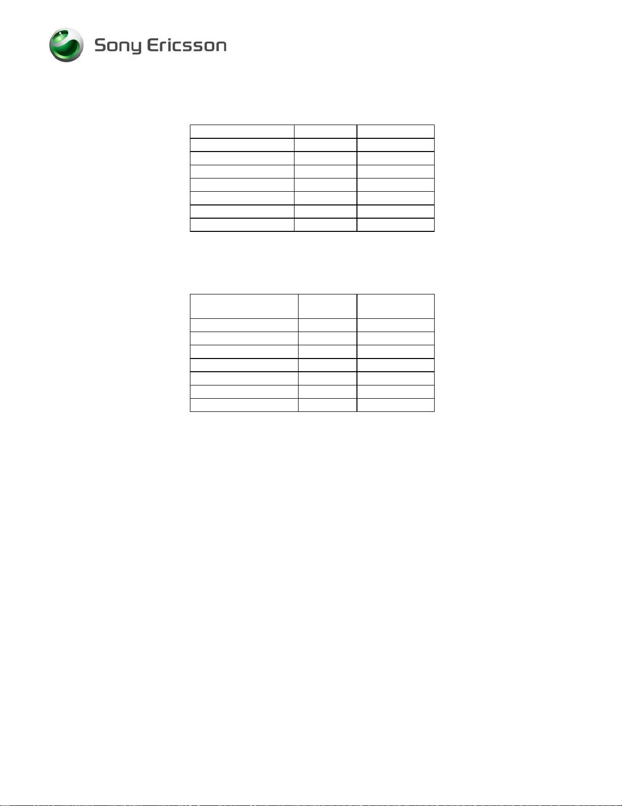
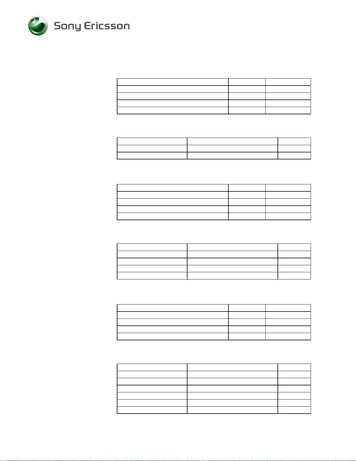
1.3 Traffic Channel (TCH) Allocation Table
Band Ch definition Any ARFCN of:
GSM 900 Low 975-979
GSM 900 Mid 36-40
GSM 900 High 120-124
GSM 1800 Low 512-516
GSM 1800 Mid 697-701
GSM 1800 High 881-885
1.4 Power Level Allocation Table
Band PL
GSM 900 Lowest 19
GSM 900 Mid 12
GSM 900 Highest 5
GSM 1800 Lowest 15
GSM 1800 Mid 8
GSM 1800 Highest 0
1.5 Test Limits
The test limits for each measurement are specified in the Sequence Tables.
1. Since a coupler introduces higher measurement inaccuracy, some
measurements in the radiated test sequences may have wider limits than
stated in the 3GPP specifications.
2. The conducted limits conform to the phase 3GPP specification.
1.6 Attenuation Factors
The different scripts must be configured with the correct attenuation factors and named
after the product that they are designed to test. The attenuation factors to be used are
stated in section 6.
Power level (PL)
definition
1219-0642 Rev 2 4(25)
Company Internal
© Sony Ericsson Mobile Communications AB
Page 5
Go/No Go Test Script Specification, Electrical
2 K330 Test Sequence - Radiated
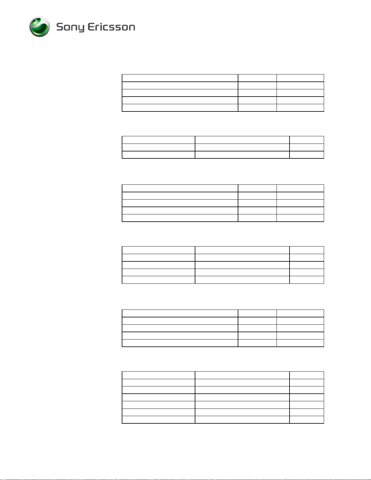
2.1 Initializing and Call Setup
Parameter Value Unit
BCCH Low Ch
TCH Low Ch
TX power level High PL
RF output power -68 dBm
System GSM 900
1219-0642 Rev 2 5(25)
Company Internal
© Sony Ericsson Mobile Communications AB
Page 6
Go/No Go Test Script Specification, Electrical
2.1.1 Sequence
1. Initialize instrument
2. Insert a test-SIM and attach a fully charged standard battery to the mobile.
It’s very important that a fully charged battery is used otherwise there is a
high risk for incorrect test results.
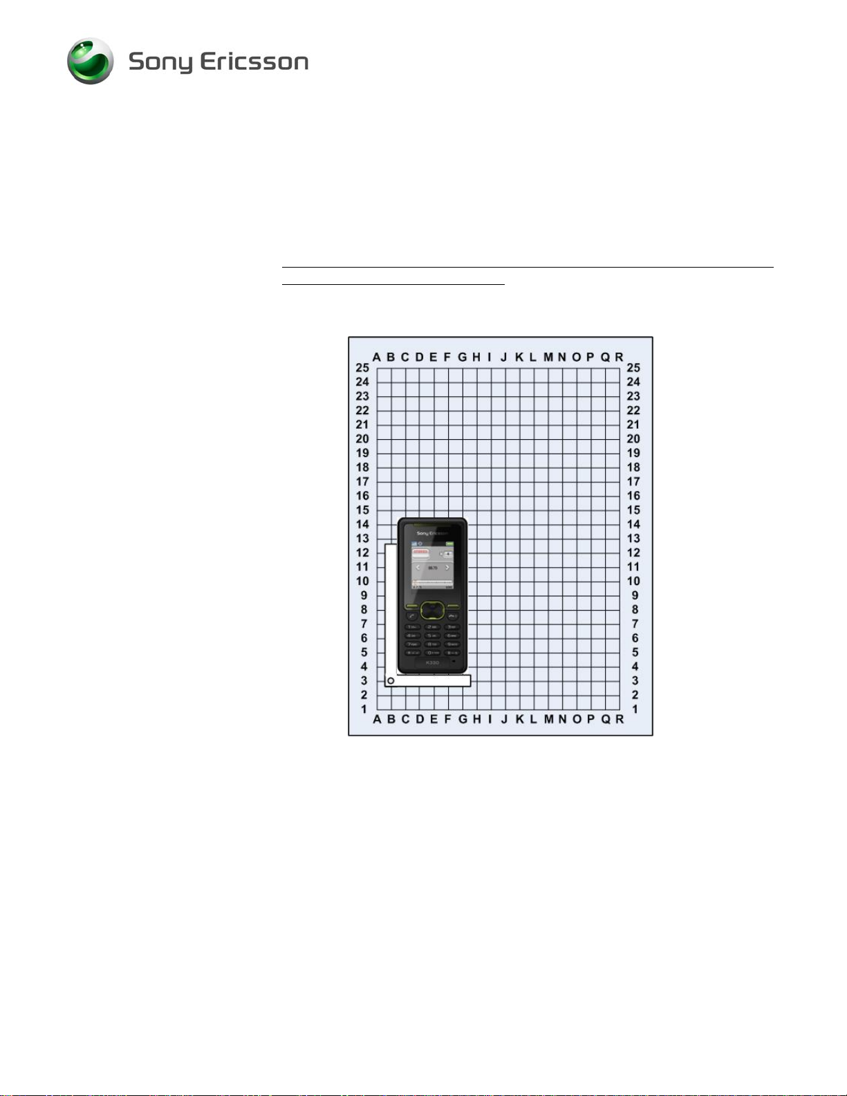
Position the mobile in the coupler according to the picture.
Rohde & Schwarz Shield Box and Coupler (B3)
3. Turn on the mobile and wait for registration.
4. Set up a call to the instrument or let the instrument call the MS.
5. Close the lid on the shielding box.
1219-0642 Rev 2 6(25)
Company Internal
© Sony Ericsson Mobile Communications AB
Page 7
Go/No Go Test Script Specification, Electrical
2.2 Audio Loopback
1. Set power level to high.
2. Activate audio loopback in the instrument.
3. Operator must acknowledge passed or failed before the test is continued.
2.3 GSM 900 Low TCH Measurements
Parameter Value Unit
TCH Low Ch
TX power level High PL
RF output power -68 dBm
System GSM 900
2.3.1 GSM 900 Low TCH Test Limits
Measurement Test Limits Unit
TX power 33 +/-4 dB
RMS Phase error 0 +/-5 Deg
Rx Level 34-50 dB
Rx Quality 0-3 Units
2.4 GSM 900 Mid TCH Measurements
Parameter Value Unit
TCH Mid Ch
TX power level Mid PL
RF output power -102 dBm
System GSM 900
2.4.1 GSM 900 Mid TCH Test Limits
Measurement Test Limits Unit
TX power 19 +/-5 dB
RMS Phase error 0 +/-5 deg
Peak Phase error 0 +/-20 deg
Freq error +/-0.1 ppm Hz
Rx Level 2-14 dB
Rx Quality 0-3 Units
1219-0642 Rev 2 7(25)
Company Internal
© Sony Ericsson Mobile Communications AB
Page 8
Go/No Go Test Script Specification, Electrical
2.5 GSM 900 High TCH Measurements
Parameter Value Unit
TCH High Ch
TX power level Low PL
RF output power -68 dBm
System GSM 900
2.5.1 GSM 900 High TCH Test Limits
Measurement Test Limits Unit
TX power 5 +/-7 dB
RMS Phase error 0 +/-5 deg
2.6 GSM 1800 Low TCH Measurements
Parameter Value Unit
TCH Low Ch
TX power level High PL
RF output power -68 dBm
System GSM 1800
2.6.1 GSM 1800 Low TCH Test Limits
Measurement Test Limits Unit
TX power 30 +/-4 dB
RMS Phase Error 0 +/-5 Deg
Rx Level 34-50 dB
RX Quality 0-3 Units
2.7 GSM 1800 Mid TCH Measurements
Parameter Value Unit
TCH Mid Ch
TX power level Mid PL
RF output power -102 dBm
System GSM 1800
2.7.1 GSM 1800 Mid TCH Test Limits
Measurement Test Limits Unit
TX power 14 +/-5 dB
RMS Phase error 0 +/-5 Deg
Peak Phase error 0 +/-20 Deg
Freq. error +/-0.1 ppm Hz
Rx Level 2-14 dB
Rx Quality 0-3 Units
1219-0642 Rev 2 8(25)
Company Internal
© Sony Ericsson Mobile Communications AB
Page 9

Go/No Go Test Script Specification, Electrical
2.8 GSM 1800 High TCH Measurements
Parameter Value Unit
TCH High Ch
TX power level Low PL
RF output power -68 dBm
System GSM 1800
2.8.1 GSM 1800 High TCH Test Limits
Measurement Test Limits Unit
TX power 0 +/-7 dB
RMS Phase error 0 +/-5 Deg
2.8.2 Call Disconnect Sequence
1. Disconnect call.
2. End test.
1219-0642 Rev 2 9(25)
Company Internal
© Sony Ericsson Mobile Communications AB
Page 10

Go/No Go Test Script Specification, Electrical
3 K330 Test Sequence - Conducted
3.1 Initializing and Call Setup
Parameter Value Unit
BCCH Mid Ch
TCH Mid Ch
TX power level High PL
RF output power -40 dBm
System GSM 900
3.1.1 Sequence
1. Initialize instrument
2. Insert a test-SIM and attach a fully charged standard battery to the mobile.
It’s very important that a fully charged battery is used otherwise there is a
high risk for incorrect test results. A dummy battery can also be used.
3. Remove the battery cover and connect the mobile to the RF probe
according to the picture.
4. Turn on the mobile and wait for registration.
5. Set up a call to the instrument or let the instrument call the MS.
1219-0642 Rev 2 10(25)
Company Internal
© Sony Ericsson Mobile Communications AB
Page 11

Go/No Go Test Script Specification, Electrical
3.2 Audio Loopback
1. Set power level to high.
2. Activate audio loopback in the instrument.
3. Operator must acknowledge passed or failed before the test is continued.
3.3 GSM 1800 Low TCH Measurements
Parameter Value Unit
TCH Low Ch
TX power level High PL
RF output power -68 dBm
System GSM 1800
3.3.1 GSM 1800 Low TCH Test Limits
Measurement Test Limits Unit
TX power 30 +/-2 dB
RMS Phase Error 0 +/-5 deg
Rx Level 36-48 dB
RX Quality 0-3 Units
3.4 GSM 1800 Mid TCH Measurements
Parameter Value Unit
TCH Mid Ch
TX power level Mid PL
RF output power -102 dBm
System GSM 1800
3.4.1 GSM 1800 Mid TCH Test Limits
Measurement Test Limits Unit
TX power 14 +/-3 dB
RMS Phase error 0 +/-5 deg
Peak Phase error 0 +/-20 deg
Freq. error +/-0.1 ppm Hz
Rx Level 4-12 dB
Rx Quality 0-3 Units
1219-0642 Rev 2 11(25)
Company Internal
© Sony Ericsson Mobile Communications AB
Page 12
Go/No Go Test Script Specification, Electrical
3.5 GSM 1800 High TCH Measurements
Parameter Value Unit
TCH High Ch
TX power level Low PL
RF output power -68 dBm
System GSM 1800
3.5.1 GSM 1800 High TCH Test Limits
Measurement Test Limits Unit
TX power 0 +/-5 dB
RMS Phase error 0 +/-5 deg
3.6 GSM 900 Low TCH Measurements
Parameter Value Unit
TCH Low Ch
TX power level High PL
RF output power -68 dBm
System GSM 900
3.6.1 GSM 900 Low TCH Test Limits
Measurement Test Limits Unit
TX power 33 +/-2 dB
RMS Phase error 0 +/-5 deg
Rx Level 36-48 dB
Rx Quality 0-3 Units
3.7 GSM 900 Mid TCH Measurements
Parameter Value Unit
TCH Mid Ch
TX power level Mid PL
RF output power -102 dBm
System GSM 900
3.7.1 GSM 900 Mid TCH Test Limits
Measurement Test Limits Unit
TX power 19 +/-3 dB
RMS Phase error 0 +/-5 deg
Peak Phase error 0 +/-20 deg
Freq error +/-0.1 ppm Hz
Rx Level 4-12 dB
Rx Quality 0-3 Units
1219-0642 Rev 2 12(25)
Company Internal
© Sony Ericsson Mobile Communications AB
Page 13
Go/No Go Test Script Specification, Electrical
3.8 GSM 900 High TCH Measurements
Parameter Value Unit
TCH High Ch
TX power level Low PL
RF output power -68 dBm
System GSM 900
3.8.1 GSM 900 High TCH Test Limits
Measurement Test Limits Unit
TX power 5 +/-5 dB
RMS Phase error 0 +/-5 deg
3.8.2 Call Disconnect Sequence
1. Disconnect call.
2. End test.
1219-0642 Rev 2 13(25)
Company Internal
© Sony Ericsson Mobile Communications AB
Page 14

Go/No Go Test Script Specification, Electrical
4 K330a Test Sequence - Radiated
4.1 Initializing and Call Setup
Parameter Value Unit
BCCH Low Ch
TCH Low Ch
TX power level High PL
RF output power -68 dBm
System GSM 850
1219-0642 Rev 2 14(25)
Company Internal
© Sony Ericsson Mobile Communications AB
Page 15

Go/No Go Test Script Specification, Electrical
4.1.1 Sequence
6. Initialize instrument
7. Insert a test-SIM and attach a fully charged standard battery to the mobile.
It’s very important that a fully charged battery is used otherwise there is a
high risk for incorrect test results.
8. Position the mobile in the coupler according to the picture.
Rohde & Schwarz Shield Box and Coupler (A10)
9. Turn on the mobile and wait for registration.
10. Set up a call to the instrument or let the instrument call the MS.
11. Close the lid on the shielding box.
1219-0642 Rev 2 15(25)
Company Internal
© Sony Ericsson Mobile Communications AB
Page 16

Go/No Go Test Script Specification, Electrical
4.2 Audio Loopback
4. Set power level to high.
5. Activate audio loopback in the instrument.
6. Operator must acknowledge passed or failed before the test is continued.
4.3 GSM 850 Low TCH Measurements
Parameter Value Unit
TCH Low Ch
TX power level High PL
RF output power -68 dBm
System GSM 850
4.3.1 GSM 850 Low TCH Test Limits
Measurement Test Limits Unit
TX power 29 +/-4 dB
RMS Phase error 0 +/-5 deg
Rx Level 34-50 dB
Rx Quality 0-3 Units
4.4 GSM 850 Mid TCH Measurements
Parameter Value Unit
TCH Mid Ch
TX power level Mid PL
RF output power -102 dBm
System GSM 850
4.4.1 GSM 850 Mid TCH Test Limits
Measurement Test Limits Unit
TX power 19 +/-5 dB
RMS Phase error 0 +/-5 deg
Peak Phase error 0 +/-20 deg
Freq error +/-0.1 ppm Hz
Rx Level 2-14 dB
Rx Quality 0-3 Units
4.5 GSM 850 High TCH Measurements
Parameter Value Unit
TCH High Ch
TX power level Low PL
RF output power -68 dBm
System GSM 850
1219-0642 Rev 2 16(25)
Company Internal
© Sony Ericsson Mobile Communications AB
Page 17

Go/No Go Test Script Specification, Electrical
4.5.1 GSM 850 High TCH Test Limits
Measurement Test Limits Unit
TX power 5 +/-7 dB
RMS Phase error 0 +/-5 deg
4.6 GSM 1900 Low TCH Measurements
Parameter Value Unit
TCH Low Ch
TX power level Low PL
RF output power -68 dBm
System GSM 1900
4.6.1 GSM 1900 Low TCH Test Limits
Measurement Test Limits Unit
TX power 0 +/-7 dB
RMS Phase Error 0 +/-5 deg
Rx Level 34-50 dB
RX Quality 0-3 Units
4.7 GSM 1900 Mid TCH Measurements
Parameter Value Unit
TCH Mid Ch
TX power level Mid PL
RF output power -102 dBm
System GSM 1900
4.7.1 GSM 1900 Mid TCH Test Limits
Measurement Test Limits Unit
TX power 14 +/-5 dB
RMS Phase error 0 +/-5 deg
Peak Phase error 0 +/-20 deg
Freq. error +/-0.1 ppm Hz
Rx Level 2-14 dB
Rx Quality 0-3 Units
4.8 GSM 1900 High TCH Measurements
Parameter Value Unit
TCH High Ch
TX power level High PL
RF output power -68 dBm
System GSM 1900
1219-0642 Rev 2 17(25)
Company Internal
© Sony Ericsson Mobile Communications AB
Page 18

Go/No Go Test Script Specification, Electrical
4.8.1 GSM 1900 High TCH Test Limits
Measurement Test Limits Unit
TX power 30 +/-4 dB
RMS Phase error 0 +/-5 deg
4.8.2 Call Disconnect Sequence
3. Disconnect call.
4. End test.
1219-0642 Rev 2 18(25)
Company Internal
© Sony Ericsson Mobile Communications AB
Page 19

Go/No Go Test Script Specification, Electrical
5 K330a Test Sequence - Conducted
5.1 Initializing and Call Setup
Parameter Value Unit
BCCH Mid Ch
TCH Mid Ch
TX power level High PL
RF output power -40 dBm
System GSM 850
5.1.1 Sequence
6. Initialize instrument
7. Insert a test-SIM and attach a fully charged standard battery to the mobile.
It’s very important that a fully charged battery is used otherwise there is a
high risk for incorrect test results. A dummy battery can also be used.
8. Remove the battery cover and connect the mobile to the RF fixture
according to the picture.
9. Turn on the mobile and wait for registration.
10. Set up a call to the instrument or let the instrument call the MS.
1219-0642 Rev 2 19(25)
Company Internal
© Sony Ericsson Mobile Communications AB
Page 20

Go/No Go Test Script Specification, Electrical
5.2 Audio Loopback
4. Set power level to high.
5. Activate audio loopback in the instrument.
6. Operator must acknowledge passed or failed before the test is continued.
5.3 GSM 850 Low TCH Measurements
Parameter Value Unit
TCH Low Ch
TX power level High PL
RF output power -68 dBm
System GSM 850
5.3.1 GSM 850 Low TCH Test Limits
Measurement Test Limits Unit
TX power 29 +/-2 dB
RMS Phase error 0 +/-5 deg
Rx Level 36-48 dB
Rx Quality 0-3 Units
5.4 GSM 850 Mid TCH Measurements
Parameter Value Unit
TCH Mid Ch
TX power level Mid PL
RF output power -102 dBm
System GSM 850
5.4.1 GSM 850 Mid TCH Test Limits
Measurement Test Limits Unit
TX power 19 +/-3 dB
RMS Phase error 0 +/-5 deg
Peak Phase error 0 +/-20 deg
Freq error +/-0.1 ppm Hz
Rx Level 4-12 dB
Rx Quality 0-3 Units
1219-0642 Rev 2 20(25)
Company Internal
© Sony Ericsson Mobile Communications AB
Page 21

Go/No Go Test Script Specification, Electrical
5.5 GSM 850 High TCH Measurements
Parameter Value Unit
TCH High Ch
TX power level Low PL
RF output power -68 dBm
System GSM 850
5.5.1 GSM 850 High TCH Test Limits
Measurement Test Limits Unit
TX power 5 +/-5 dB
RMS Phase error 0 +/-5 deg
5.6 GSM 1900 Low TCH Measurements
Parameter Value Unit
TCH Low Ch
TX power level Low PL
RF output power -68 dBm
System GSM 1900
5.6.1 GSM 1900 Low TCH Test Limits
Measurement Test Limits Unit
TX power 0 +/-5 dB
RMS Phase error 0 +/-5 deg
Rx Level 36-48 dB
RX Quality 0-3 Units
5.7 GSM 1900 Mid TCH Measurements
Parameter Value Unit
TCH Mid Ch
TX power level Mid PL
RF output power -102 dBm
System GSM 1900
5.7.1 GSM 1900 Mid TCH Test Limits
Measurement Test Limits Unit
TX power 14 +/-3 dB
RMS Phase error 0 +/-5 deg
Peak Phase error 0 +/-20 deg
Freq. error +/-0.1 ppm Hz
Rx Level 4-12 dB
Rx Quality 0-3 Units
1219-0642 Rev 2 21(25)
Company Internal
© Sony Ericsson Mobile Communications AB
Page 22

Go/No Go Test Script Specification, Electrical
5.8 GSM 1900 High TCH Measurements
Parameter Value Unit
TCH High Ch
TX power level High PL
RF output power -68 dBm
System GSM 1900
5.8.1 GSM 1900 High TCH Test Limits
Measurement Test Limits Unit
TX power 30 +/-2 dB
RMS Phase error 0 +/-5 deg
5.8.2 Call Disconnect Sequence
1. Disconnect call.
2. End test.
1219-0642 Rev 2 22(25)
Company Internal
© Sony Ericsson Mobile Communications AB
Page 23

Go/No Go Test Script Specification, Electrical
6 Attenuation Factors
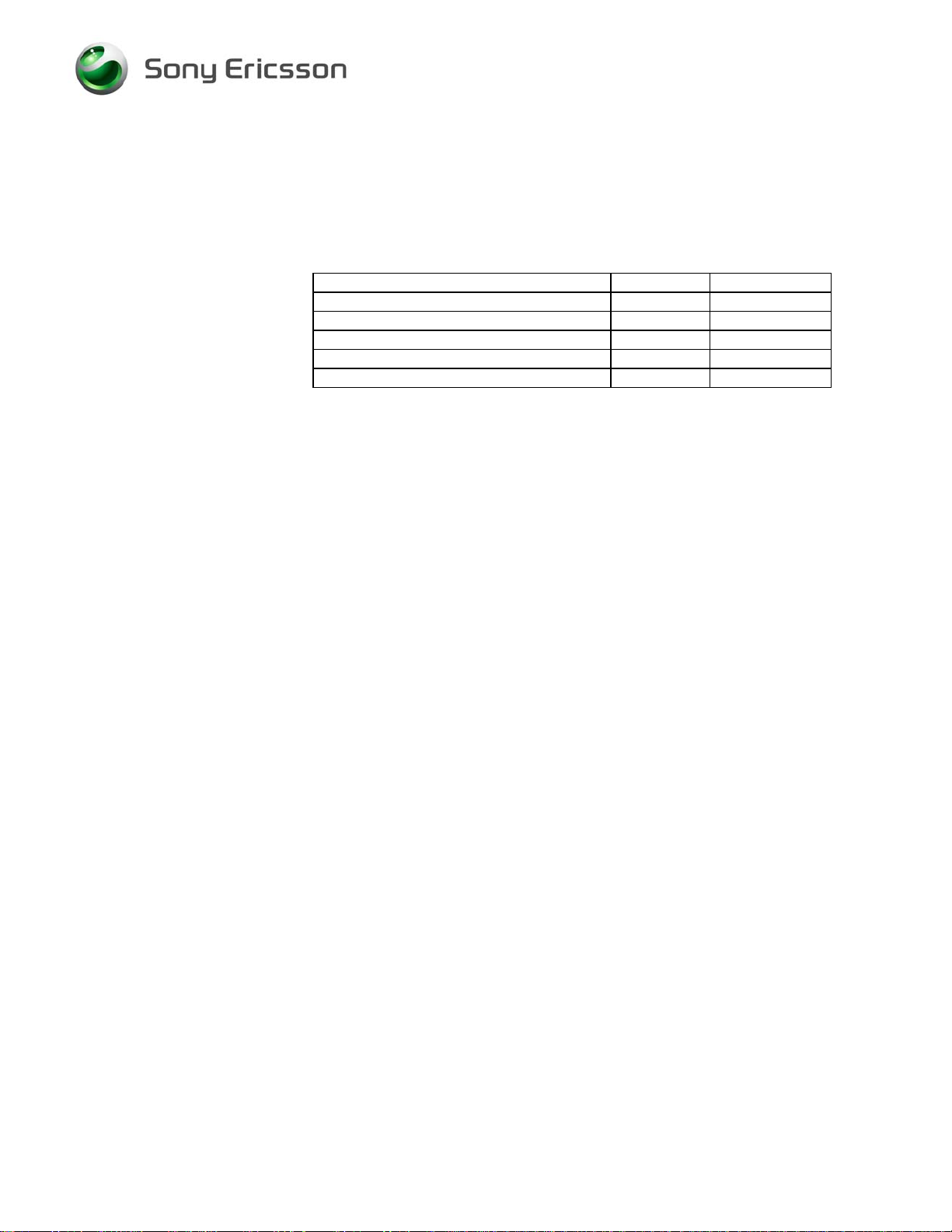
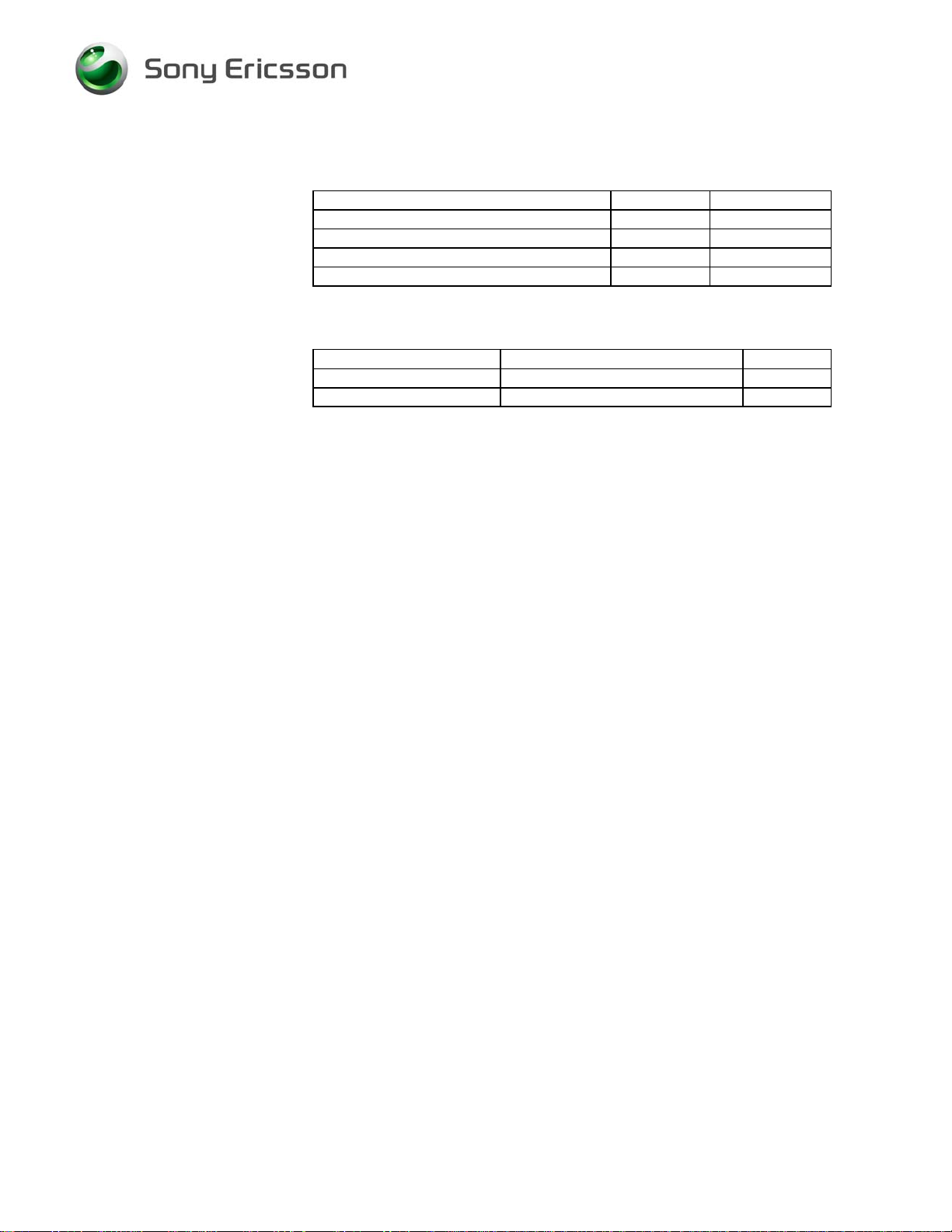
6.1 Radiated Loss Values
The following values shall be used when testing the Sony Ericsson K330 in the Rohde &
Schwarz RF shield box (R&S part # 1150.1008.02) using the Rohde & Schwarz coupler
(R&S part # 1150.0801.02) and SEMC RF-cable (SEMC part # RPM 119 855). A
precision type N Male to SMA Female adapter is required to connect the cable to the RF
shield box.
NOTE! These values are only valid if you are using the Grid Positioning Plate (R&S
part number 1158.9789.00)
Attenuation
Band Channel
GSM 900
GSM 1800
GSM 850
GSM 1900
Low 5.4 4.29
Mid 9.5 3.66
High 10.6 2.24
Low 14.7 12.92
Mid 15.1 13.05
High 13.4 14.25
Low 10.47 13.00
Mid 8.05 13.54
High 9.88 13.81
Low 16.96 17.97
Mid 17.13 18.99
High 20.47 16.97
RX TX
1219-0642 Rev 2 23(25)
Company Internal
© Sony Ericsson Mobile Communications AB
Page 24

Go/No Go Test Script Specification, Electrical
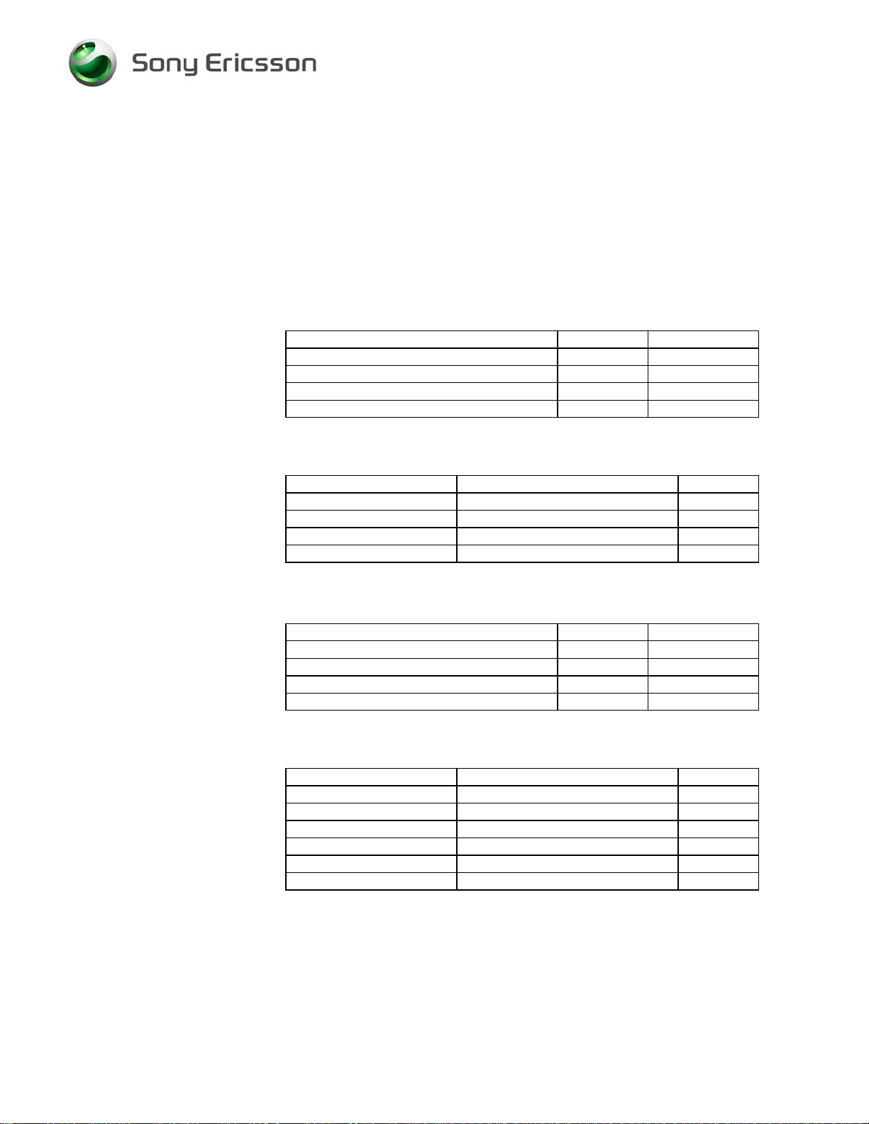
6.2 Conducted Loss Values
The following values shall be used when testing the Sony Ericsson K330 with a Direct Line
connection. The Direct Line connection shall consist of a SEMC RF-cable (SEMC part # RPM
119 855) and RF Probe (SEMC part # SXA 109 6356).
Attenuation
Band Channel*
RX TX
GSM 900 ALL 0.8 0.8
GSM 1800 ALL 1.3 1.3
1219-0642 Rev 2 24(25)
Company Internal
© Sony Ericsson Mobile Communications AB
Page 25
Go/No Go Test Script Specification, Electrical
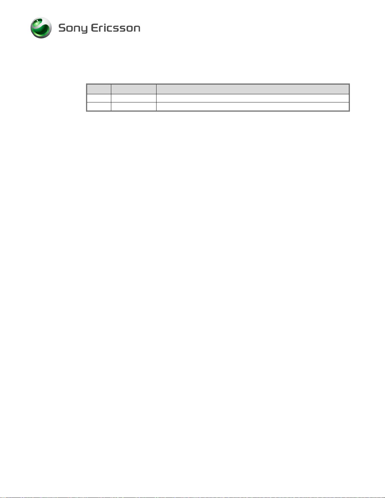
7 Revision history
Rev. Date Changes / Comments
1 2008-11-14 Initial Release
2 2008-11-14 No changes
1219-0642 Rev 2 25(25)
Company Internal
© Sony Ericsson Mobile Communications AB
 Loading...