

Page 1
Installation Instruction, Electrical
Installation Instruction - Electrical
Applicable for K200 and K220
Contents
General............................................................................................................... 2
1
2 Go/No Go Testing.............................................................................................. 2
2.1 Test Set-up Go/No Go test.................................................................... 2
2.2 RF Connections Antenna Coupler......................................................... 3
2.3 RF Connections Antenna adapter (optional) ......................................... 3
2.4 Test Set ................................................................................................. 3
2.5 Power Supply ........................................................................................ 3
2.6 Dummy Battery...................................................................................... 3
2.7 GPIB card and cable ............................................................................. 3
2.8 RF Connection ...................................................................................... 3
2.9 SonyEricsson programming interface – SEPI ....................................... 3
2.10 Sony Ericsson programming interface cable......................................... 4
3 General Equipment ........................................................................................... 5
3.1 Test Set up ............................................................................................ 5
3.2 Computer............................................................................................... 6
3.3 Service Card Reader and Service Card ................................................ 6
3.4 Label Printer (optional) .......................................................................... 6
3.5 Infrared Device ...................................................................................... 6
4 Software ............................................................................................................. 7
4.1 EMMA III................................................................................................ 7
4.2 Labelmake II software (optional) ........................................................... 7
4.3 SERP Go/No Go Test Script ................................................................. 7
4.3.1 Go/No Go script..................................................................................... 8
5 Revision History................................................................................................ 9
1/000 21-2/FEA 209 544/127 B
Company Internal
© Sony Ericsson Mobile Communications AB
Page 2
Installation Instruction, Electrical
1 General
The Electrical Installation Instructions describes the procedures for installing all of the
hardware and software needed to perform testing, calibration, software loading and
repair activities at an Electrical level for the Sony Ericsson products specified.
2 Go/No Go Testing
There are two options for performing a Go No/Go test. One is to use an RF Fixture
and the other is to use an antenna coupler together with a shielding box.
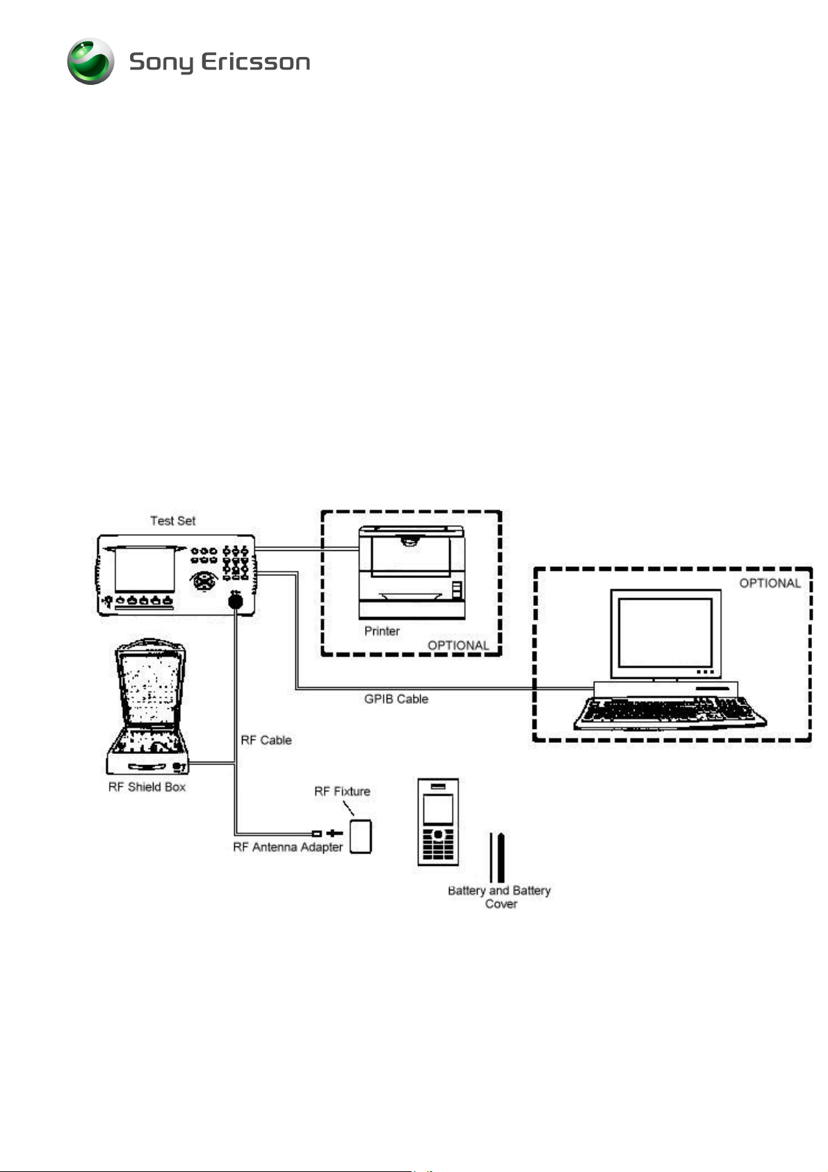
2.1 Test Set-up Go/No Go test
All test hardware necessary for this test set up is documented in the Electrical
Equipment List.
*RF fixture N/A
1/000 21-2/FEA 209 544/127 B
Company Internal
© Sony Ericsson Mobile Communications AB
2(9)
Page 3
Installation Instruction, Electrical
2.2 RF Connections Antenna Coupler
Connect the RF Cable between the RF-port of the Test set and the RF Shield box.
The Antenna Coupler should be installed into the RF Shield Box according to
manufacturer instructions.
2.3 RF Connections Antenna adapter (optional)
Connect the RF-cable between the RF-port of the Test set and the Antenna adapter.
Assemble the RF adapter to the RF-holder according to the information in the Test
Instruction Electrical.
2.4 Test Set
A Test Set approved according to the Instrument List must be used.
It should be installed according to the Instrument Manufacturer Instructions.
2.5 Power Supply
Power Supply according to Instrument List must be used.
2.6 Dummy Battery
Dummy Battery is to be used together with a power supply to power the phone during
the calibration. Connect the cables from the Dummy Battery to the power supply, red
cable to positive output terminal and black cable to negative output terminal.
2.7 GPIB card and cable
Use GPIB card and cable according to the Equipment List. Use the GPIB cable to
connect the GPIB card to the test instrument.
2.8 RF Connection
Use RF adapter according to Equipment List. Connect the RF adapter to the RF
cable. The RF adapter is snapped on the phone.
2.9 SonyEricsson programming interface – SEPI
The USB programming interface is delivered with the necessary software and
instruction for installation. The USB programming interface (SEPI) should be
connected to an USB-port on the computer. A standard Sony Ericsson Mobile
Communication charger, CST-60 must be connected to the SEPI.
1/000 21-2/FEA 209 544/127 B
Company Internal
© Sony Ericsson Mobile Communications AB
3(9)
Page 4

Installation Instruction, Electrical
2.10 Sony Ericsson programming interface cable
The cable is the interface between the USB programming interface (SEPI) and the
phone.
1/000 21-2/FEA 209 544/127 B
Company Internal
© Sony Ericsson Mobile Communications AB
4(9)
Page 5

Installation Instruction, Electrical
3 General Equipment
3.1 Test Set up
General Test set up to perform SW loading and manual test according to Test
Instruction. All necessary hardware for this test set up is documented in the Electrical
Equipment list.
1/000 21-2/FEA 209 544/127 B
Company Internal
© Sony Ericsson Mobile Communications AB
5(9)
Page 6

Installation Instruction, Electrical
3.2 Computer
IBM compatible computer is required. The computer should include at least two USBports. Refer to Equipment List for minimum requirements.
3.3 Service Card Reader and Service Card
The Service Card Reader is delivered with the necessary software and instructions
for installation. The Service Card Reader should be connected to an USB-port on the
computer.
3.4 Label Printer (optional)
A Zebra printer model 90xi, 90xiII or 4000 deluxe shall be used. Connect the printer
with a standard RS 232 serial printer cable [refer to the Zebra printer manual] to the
serial port on the computer. Read the Zebra installation manual for more information
about the installation.
3.5 Infrared Device
RS 232 or USB type infrared adapter may be used. Install according to the
manufactures instructions.
1/000 21-2/FEA 209 544/127 B
Company Internal
© Sony Ericsson Mobile Communications AB
6(9)
Page 7

Installation Instruction, Electrical
4 Software
4.1 EMMA III
EMMA III contains all software required to service the product. Installation and user
manuals are available in the EMMA III start page.
http://ma3.extranet.sonyericsson.com/ma3/
4.2 Labelmake II software (optional)
LabelMake II is an application installed through Java Web Start.
Access the Labelmake software from CSPN
You will find LabelMake II in the dropdown menu on the CSPN web page.
http://cspn.extranet.sonyericsson.com
Press “START LabelMake II “button and you will be directed to the LABELMAKE II
client page.
Product labels are downloaded on-line from a remote server database.
Web page.
4.3 SERP Go/No Go Test Script
SERP stands for “Sony Ericsson Repair Platform”. It is an application used for
testing, calibrating and repairing Sony Ericsson mobile phones.
NOTE! For K200 and K220, SERP can only be used for Go/No-Go tests
Download the latest revision of the SERP application from CSPN
Instructions/Standard/SERP Install Package) or through the use of the SERP
Online Update Tool (OUT).
(Repair
1. Unzip the file and open the file “SERP_Installation.doc” for installation
instructions.
2. After SERP is installed a file titled “SERPINFO.htm” will be placed on the
Windows Desktop. This file contains numerous documents including:
• SERP Users Manual – This document contains system requirements, release
notes, fault reporting instructions, supported test instruments, installation
procedures and detailed operating instructions.
• SERP Troubleshooting Guide – This document contains a few
troubleshooting steps that should be reviewed before reporting issues to Sony
Ericsson.
• SERP Trouble Report Form – This form should be filled out when reporting
SERP issues to the regional support team.
• SERP OUT Quick Guide – This document contains system requirements,
registration information and general user guidelines for the OUT application.
1/000 21-2/FEA 209 544/127 B
Company Internal
© Sony Ericsson Mobile Communications AB
7(9)
Page 8

Installation Instruction, Electrical
4.3.1 Go/No Go script
An approved Sony Ericsson Test Script must be installed in the Test Instrument. The
script can be downloaded from CSPN
Repair Instructions / Standard.
Install the script according to the Instrument Manufacture’s Instruction.
. The Test Script is located on CSPN under
1/000 21-2/FEA 209 544/127 B
Company Internal
© Sony Ericsson Mobile Communications AB
8(9)
Page 9

Installation Instruction, Electrical
5 Revision History
Rev. Date Changes / Comments
A 2007-05-03 First release
B 2007-07-11 Go/No Go test added
1/000 21-2/FEA 209 544/127 B
Company Internal
© Sony Ericsson Mobile Communications AB
9(9)
 Loading...