

Page 1

Application Note
Embedded Applications
Fixed Cellular Telephone
Page 2

First edition (September 2004)
Sony Ericsson Mobile Communications. publishes this manual without
making any warranty as to the content contained herein. Further Sony
Ericsson Mobile Communications. reserves the right to make modifications,
additions and deletions to this manual due to typographical errors, inaccurate
information, or improvements to programs and/or equipment at any time and
without notice. Such changes will, nevertheless be incorporated into new
editions of this manual.
All rights reserved.
© Sony Ericsson Mobile Communications., 2004
Page 3

EMBEDDED APPLICATIONS FCT
Contents
Contents.....................................................................................................3
1 Introduction ........................................................................................4
2 FCT design.......................................................................................... 5
2.1 Keypad ......................................................................................................5
2.1.1 Operation .......................................................................................5
2.1.2 Set-up ............................................................................................5
2.1.3 Keypad Configuration ....................................................................6
2.2 I
2
C LCD .....................................................................................................7
2.2.1 Operation .......................................................................................7
2.2.2 Set-up ............................................................................................7
2.3 Fixed Cellular Terminal Application {FCT.sc} ..........................................12
LZT 123 8016 R1A 3
Page 4

EMBEDDED APPLICATIONS FCT
1 Introduction
When combined with the embedded applications scripting
language, interfacing a keypad and LCD to the radio
device can provide a simple man-machine interface
without the need for external host controllers.
This application note details the use the I2C interface for
the LCD screen and the intrinsic functions to control a 5 x
4 keypad matrix.
LZT 123 8016 R1A 4
Page 5

EMBEDDED APPLICATIONS FCT
2 FCT design
Here an application of a fixed-cellular-terminal (FCT) is
used to illustrate the interfacing of a keypad and I
2
C LCD
to the radio device.
Application Block Diagram (Fixed cellular terminal)
2.1 Keypad
2.1.1 Operation
When the script executes it calls a key-scan routine in an
endless loop. When no key is pressed the key-scan
routine returns the code 0xFF. A key-press is detected
when any one of the KeyRow inputs receives a logic low.
The key-scan routine identifies which KeyColumn driver
was active when the key-press was detected and the
routine provides a return code representing the
combination of row and column.
2.1.2 Set-up
The keypad driver setup uses the function kyc() to define
which rows and columns are activated for the application.
This allows the user to select the most suitable keypad
size and avoids tying up control I/O which would be more
usefully applied elsewhere in the application.
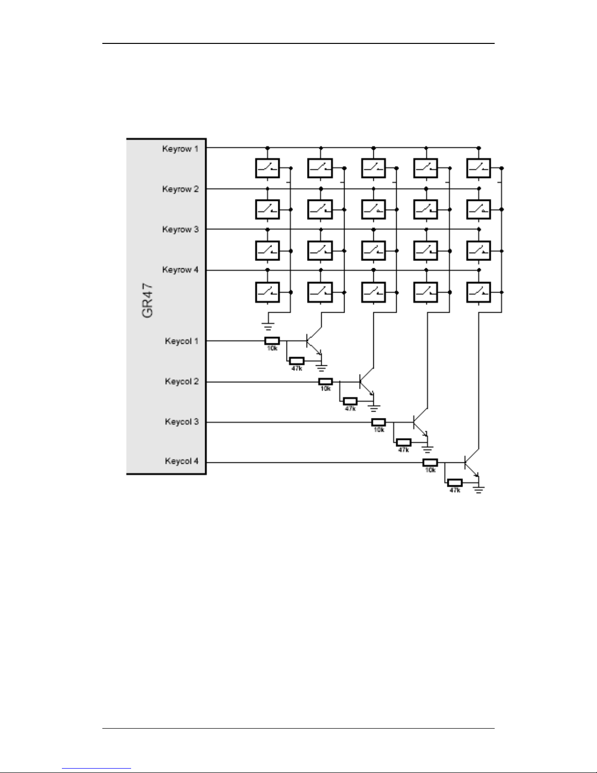
This application example utilizes the full complement of
column drivers and row receivers to provide a 20 key
interface.
LZT 123 8016 R1A 5
Page 6
EMBEDDED APPLICATIONS FCT
The GND ground connection may be used as a column
driver. When used, this is referred to as Column 0.
Note!
Keypad Interface Schematic
2.1.3 Keypad Configuration
The key pad is configured using intrinsic functions within
embedded applications, further information can be found
in the IDE help section.
LZT 123 8016 R1A 6
Page 7

EMBEDDED APPLICATIONS FCT
2.2 I2C LCD
2.2.1 Operation
The I
2
C device used is a general purpose IO controller
which is connected to a parallel port controlled LCD
module.
When the script executes, it writes I
2
C data to set the
GPIO chip outputs. The GPIO outputs are connected to
the data and control lines of the LCD module. The high
speed of the I
2
C data output enables us to create a set of
up to 8 discrete waveforms which meet the requirements
of the LCD electrical interface. The required timings of the
LCD interface are provided in the following pages, along
with the I
2
C LCD interface diagrams and pin-out.
The chosen LCD uses either an 8 bit or a 4 bit data
interface with 3 additional control signals RS, E, R/W. The
LCD is operating in 4 bit mode so can provide the 7
required signals with a single 8 bit I
2
C-GPIO converter.
The I2C register has been defined as follows:
BIT
P7 P6 P5 P4 P3 P2 P1 P0
LCD
n/c E RS R/W D7 D6 D5 D4
I2C register configuration
2.2.2
Set-up
The I2C driver uses the function I2C() to set the clock rate
for the I
2
C interface. There are two rates available,
100kHz and 400 kHz.
This application example uses the 400kHz rate.
The I
2
C GPIO interface IC is available from Philips
Semiconductor and has manufacturers part number
PCT8574A. The address range of the device is 0x70 to
0x7F in hexadecimal notation. For this application the
address’s 0x70 have been selected for writing data and
0x71 for reading data.
To write an 8 bit data instruction to the I
2
C port we use the
intrinsic function i2w(Addr, NumOfBytes, Data, &Ack).
LZT 123 8016 R1A 7
Page 8

EMBEDDED APPLICATIONS FCT
LCD Interface Schematic
LCD Interface
LZT 123 8016 R1A 8
Page 9

EMBEDDED APPLICATIONS FCT
Supplier Varitronix Limited (Samsung KS0070B LCD
Controller)
Part
Number
MDLS16265SSXLV (3 Volt)
Description 16 Characters x 2 Lines
LCD spec
PIN # NAME DESCRIPTION
1 VSS Ground
2 VDD Logic Supply (2.75V)
3 VO LCD Supply (0V)
4 RS Register Select
5 R/W Read/Write
6 E Enable
7 DB0 Data0
8 DB1 Data1
9 DB2 Data2
10 DB3 Data3
11 DB4 Data4
12 DB5 Data5
13 DB6 Data6
14 DB7 Data7
15 LED(+) Backlight Anode
16 LED(-) Backlight Cathode
Pinout
Mode Item Symb
ol
Min Typ Max Unit
E Cycle Time Tc 1400 - -
E Rise / Fall Time tr, tf - - 25
Write
Mode
E Pulse Width (High, Tw 400 - -
LZT 123 8016 R1A 9
Page 10

EMBEDDED APPLICATIONS FCT
Low)
R/W and RS Setup
Time
tsu1 60 - -
R/W and RS Hold
Time
th1 20 - -
Data Setup Time tsu2 140 - -
(Refer to
Fig-2.5)
Data Hold Time th2 10 - -
ns
E Cycle Time Tc 1400 - -
E Rise / Fall Time tr,tf - - 25
E Pulse Width (High,
Low)
Tw 400 - -
R/W and RS Setup
Time
Tsu 60 - -
R/W and RS Hold
Time
Th 20 - -
Data Setup Time tD - - 36
0
Read
Mode
(Refer to
Fig-2.6)
Data Hold Time tDH 5 - -
ns
(VDD = 2.7 to 4.5 V, Ta = -30 to +85
o
C)
LCD AC Timing Characteristics
Write Mode Timing Diagram
LZT 123 8016 R1A 10
Page 11

EMBEDDED APPLICATIONS FCT
Read Mode Timing Diagram
LZT 123 8016 R1A 11
Page 12

EMBEDDED APPLICATIONS FCT
2.3 Fixed Cellular Terminal Application {FCT.sc}
The overall code that was generated is given below.
char KEY_IN2 = 10;
char KEY_IN3 = 11;
char KEY_IN4 = 12;
char RI = 1;
char DTR = 2;
char DCD = 3;
char DSR = 4;
char CTS = 5;
char CharTable[20] =
{1,2,3,0x0a,0x0b,4,5,6,0x0c,0x0d,7,8,9,0x0e,0x0f,0x2a,0,0x23,0x12,0x13};
main()
{
int val, aterr, resCmdSize;
int i; /*counter for keyread loop*/
char resCmd[20];
char resndCmd[30];
char sndCmd[30];
char valstr[2];
char PREVKEYPRESSED = 0;
char CALLING = 0;
/*setup All Key pins*/
spc(RI,0); /* turn off RI */
spc(DTR,0); /* turn off DTR */
spc(DCD,0); /* turn off DCD */
spc(DSR,0); /* turn off DSR */
spc(CTS,0); /* turn off CTS */
io(4,KEY_IN2,0); /*switch in I2*/
io(4,KEY_IN3,0); /*switch in I3*/
io(4,KEY_IN4,0); /*switch in I4*/
valstr[0] = ’\0’;
valstr[1] = ’\0’;
sndCmd[0] = ’\0’; /*NUL terminate send string*/
resndCmd[0] = ’\0’; /*NUL terminate send string*/
aterr = atcrt(); /*AT channel setup */
scpy(sndCmd, “ATD”);
LCDinit(); /*Setup LCD */
val = kyc(0xFF, 1); /*use maximal keyboard*/
while(1)
{
val = kyr();
if(val != 0xFF)
{
if(!PREVKEYPRESSED)
{
PREVKEYPRESSED = 1;
prtf(“key pressed = %x”,val);
val = CharTable[val];
if((val < 0x0a) || (val == 0x2a) || (val == 0x23))
{
if(val <0x0a)
{
itoa(val,valstr,2);
}
LZT 123 8016 R1A 12
Page 13

EMBEDDED APPLICATIONS FCT
LZT 123 8016 R1A 13
else
{
*valstr = val;
}
LCDdata (*valstr);
scat(sndCmd, valstr);
}
else if(val == 0x0a) /* SEND key*/
{
if(gtb(8)==1) /*incoming call so answer*/
{
aterr = atsnd(“ATA”, resCmd, 3, 20,
&resCmdSize);
LCDcontrol(0x01);
LCDtext(“Answering”, 9);
}
else if(!(gtf(9))) /*outgoing call so dial number*/
{
CALLING = 1;
LCDcontrol(0xc0);
LCDtext(“Dial”, 4);
scat (sndCmd, “;”);
aterr = atsnd (sndCmd, resCmd,
slen(sndCmd), 20, &resCmdSize);
prtf (“\nsent AT command \n%s”,
sndCmd);
scpy(resndCmd, sndCmd);
}
}
else if(val == 0x0b) /* REJECT key*/
{
LCDcontrol(0x01);
scpy(sndCmd, “ATD”);
aterr = atsnd (“ATH”, resCmd, 3, 20,
&resCmdSize);
}
else if(val == 0x0c) /* REDIAL key*/
{
if(!(gtf(9))) /*outgoing call so dial number*/
{
CALLING = 1;
LCDcontrol(0x01);
LCDtext(“Redial”, 6);
aterr = atsnd (resndCmd, resCmd,
slen(resndCmd),
20, &resCmdSize);
prtf (“\nsent AT command \n%s”,
resCmd);
}
}
}
}
else
{
PREVKEYPRESSED = 0;
prtf(“No Key Pressed”);
}
if(gtb(8)==1) /*incoming call so answer*/
{
if(!CALLING)
{
CALLING = 1;
Page 14

EMBEDDED APPLICATIONS FCT
LZT 123 8016 R1A 14
LCDcontrol(0x01);
LCDtext(“*Incoming Call*”, 15);
}
}
else
{
CALLING = 0;
}
} /* while (1) */
aterr = atdst(); /*destroy AT channel*/
val = kyd(); /*destroy keypad config*/
} /* main */
LCDdata(int Data)
{
char Addr2;
char DataWr[4];
char HiBits;
char LoBits;
char Ack;
Addr2= 0x70;
HiBits = Data >> 4;
LoBits = Data & 0x0f;
DataWr[0] = HiBits | 0x60;
DataWr[1] = HiBits | 0x20;
DataWr[2] = LoBits | 0x60;
DataWr[3] = LoBits | 0x20;
i2w(Addr2,4,DataWr, &Ack);
}
LCDcontrol(int control)
{
char Addr2;
char DataWr[4];
char HiBits;
char LoBits;
char Ack;
Addr2= 0x70;
HiBits = control >> 4;
LoBits = control & 0x0f;
DataWr[0] = HiBits | 0x40;
DataWr[1] = HiBits;
DataWr[2] = LoBits | 0x40;
DataWr[3] = LoBits;
i2w(Addr2,4,DataWr, &Ack);
}
LCDinit()
{
char Addr2;
char DataWr[4];
char Data;
char Ack;
Addr2= 0x70;
I2C(0);
/* Set to 8 bit mode */
/* And Write dummy 8 bit instruction 0001xxxx */
LCDcontrol(0x31);
/* Set to 4 bit mode and perform initialization */
Data = 0x02;
DataWr[0] = 0x42;
DataWr[1] = 0x02;
i2w(Addr2,2,DataWr, &Ack);
i2w(Addr2,2,DataWr, &Ack);
Data = 0x0c;
Page 15

EMBEDDED APPLICATIONS FCT
LZT 123 8016 R1A 15
DataWr[0] = 0x4c;
DataWr[1] = 0x0c;
i2w(Addr2,2,DataWr, &Ack);
LCDcontrol(0x0f);
LCDcontrol(0x01);
LCDcontrol(0x06);
}
LCDtext(char *textstr, int textlen)
{
char n;
for(n=0; n<textlen; n++)
LCDdata(textstr[n]);
}
 Loading...