

Page 1

Working Instruction, Mechanical
Working Instruction, Mechanical
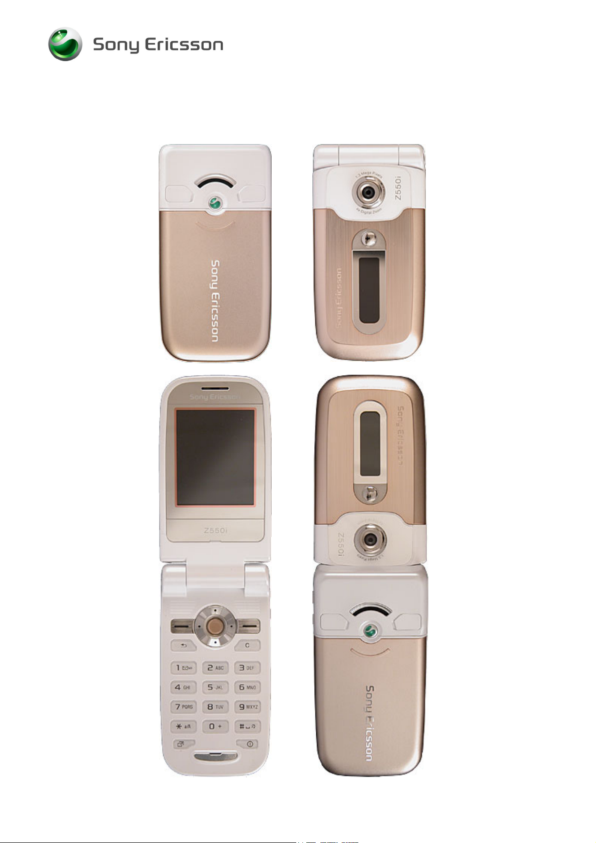
Applicable for Z550i, Z550c, Z550a, Z558i & Z558c
CONTENTS
1 Introduction .............................................................................. 3
1.1 Equipment.................................................................................4
1.2 General cautions ...................................................................... 5
2 Disassembly ............................................................................. 6
2.1 Lower unit .................................................................................7
2.1.1 Battery Cover & Battery......................................................... 8
2.1.2 Screw Covers........................................................................ 9
2.1.3 Lower Outer Cover .............................................................. 10
2.1.4 Speaker Box........................................................................ 12
2.1.5 PCBA ..................................................................................13
2.1.6 Keypad ................................................................................ 14
2.1.7 Side Ring Strap ................................................................... 15
2.1.8 Side Ring............................................................................. 16
2.1.9 Lower Inner Cover...............................................................17
2.2 Upper unit ...............................................................................19
2.2.1 Co-Brand Screw Covers...................................................... 20
2.2.2 Upper Outer Cover .............................................................. 21
2.2.3 Upper Inner Cover...............................................................23
3 Replacements......................................................................... 25
3.1 Battery Cover..........................................................................26
3.2 Screw Covers.......................................................................... 26
3.3 Lower Outer Cover ................................................................. 26
3.4 Speaker Box............................................................................ 26
3.5 Side Ring Strap....................................................................... 26
3.6 Side Ring.................................................................................26
3.7 Lower Inner Cover..................................................................26
3.8 Co-Brand Screw Covers ........................................................ 27
3.9 Upper Outer Cover ................................................................. 27
3.10 Upper Inner Cover .................................................................. 27
3.11 Dual LCD .................................................................................28
3.12 Main FPC .................................................................................31
3.13 Camera ....................................................................................34
3.14 Vibrator & Vibrator Support ..................................................36
3.15 Magnet.....................................................................................38
3.16 Receiver ..................................................................................39
3.17 Hinge 40
3.18 Sub Display Window .............................................................. 42
3/000 21-1/FEA 209 544/115 C
Company Internal
© Sony Ericsson Mobile Communications AB
Page 2

Working Instruction, Mechanical
3.19 Electric Cloths ........................................................................ 43
3.20 Dome Sheet Array .................................................................. 44
3.21 System Connector..................................................................45
3.22 Liquid Intrusion Indicator ...................................................... 46
3.23 Label 47
4 Reassembly ............................................................................ 48
4.1 Upper unit ...............................................................................49
4.1.1 Upper Inner Cover...............................................................50
4.1.2 Lower Inner Cover...............................................................51
4.1.3 Upper Outer Cover .............................................................. 53
4.1.4 Co-Brand Screw Covers...................................................... 54
4.2 Lower unit ...............................................................................55
4.2.1 Side Ring............................................................................. 56
4.2.2 Side Ring Strap ................................................................... 57
4.2.3 Keypad ................................................................................ 58
4.2.4 PBA ..................................................................................... 59
4.2.5 Speaker Box........................................................................ 60
4.2.6 Lower Outer Cover .............................................................. 61
4.2.7 Screw Covers...................................................................... 62
4.2.8 Battery & Battery Cover....................................................... 63
5 Revision history ..................................................................... 64
3/000 21-1/FEA 209 544/115 C
Company Internal
© Sony Ericsson Mobile Communications AB
2(64)
Page 3
Working Instruction, Mechanical
1 Introduction
Z550
3/000 21-1/FEA 209 544/115 C
Company Internal
© Sony Ericsson Mobile Communications AB
3(64)
Page 4
Working Instruction, Mechanical
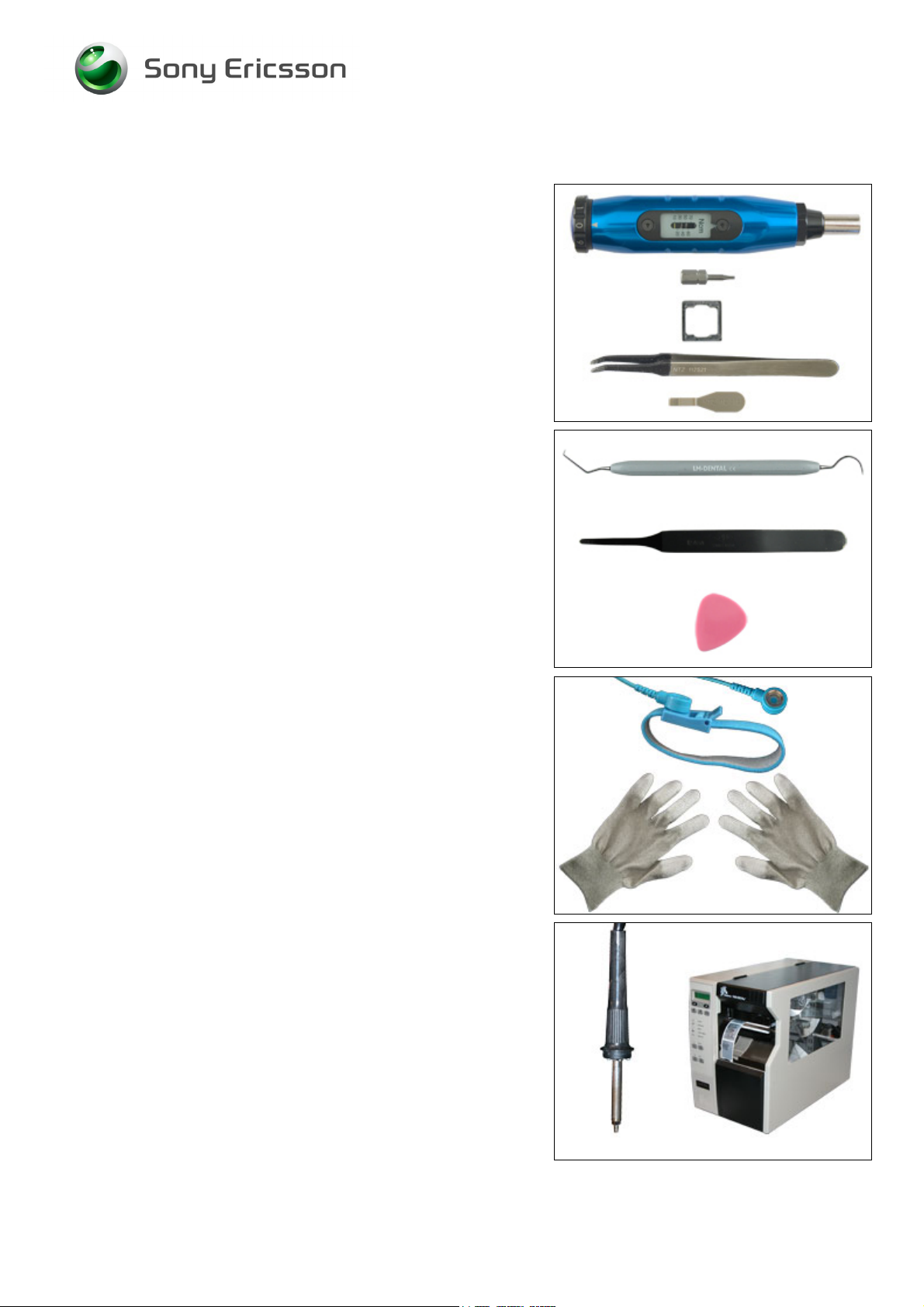
1.1 Equipment
SPECIAL TOOLS
• NTZ 122 459 Torque screwdriver (or equivalent)
• NTZ 122 288 Torx bit no. 6
• NTZ 112 1067 Mega camera removal tool
• NTZ 122 521 Flex film assembly tool
• NTZ 112 302/2 Front opening tool
STANDARD TOOLS
Standard tools have to be locally purchased
• Dentist hook
• Blunt pair of tweezers
• Guitar pick
ESD EQUIPMENT
Protect the phone from ESD damages whenever it has
been opened by using:
• ESD-wristband
• ESD-gloves
LABEL EQUIPMENT
The following special equipment is required when replacing
or installing a new label:
• Hot air flow solder station
• Zebra printer connected to computer
3/000 21-1/FEA 209 544/115 C
Company Internal
© Sony Ericsson Mobile Communications AB
4(64)
Page 5
Working Instruction, Mechanical
1.2 General cautions
The following cautions are considered to be generic for all phone models and will not be repeated in
the Disassembly, Replacements and Reassembly sections:
•
KEEP ALL CONTACT SURFACES CLEAN!
BE CAREFUL WHEN USING TOOLS LIKE THE DENTIST HOOK, TWEEZERS, OPENING TOOLS, GUITAR PICK
ETC. TO AVOID SCRATCHES OR DAMAGES TO THE EXTERIOR AND INTERIOR PARTS OF THE PHONE!
BE CAREFUL NOT TO DAMAGE ANY CONTACT SPRINGS!
•
•
REMEMBER TO REMOVE THE PROTECTION FOILS ON NEW PARTS SUCH AS THE LCD!
•
NEVER TOUCH THE DISPLAY GLASS!
•
USE AIR BLOW EQUIPMENT TO KEEP THE FRONT WINDOW AND DISPLAY MODULE DUST FREE!
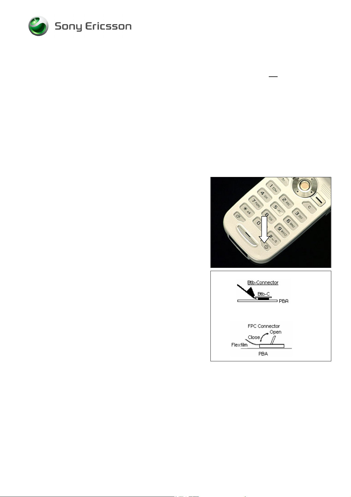
Press the On/Off button to turn off the phone.
How to open a board-to-board connector with the front
opening tool.
How to open and close a FPC connector.
3/000 21-1/FEA 209 544/115 C
Company Internal
© Sony Ericsson Mobile Communications AB
5(64)
Page 6
Working Instruction, Mechanical
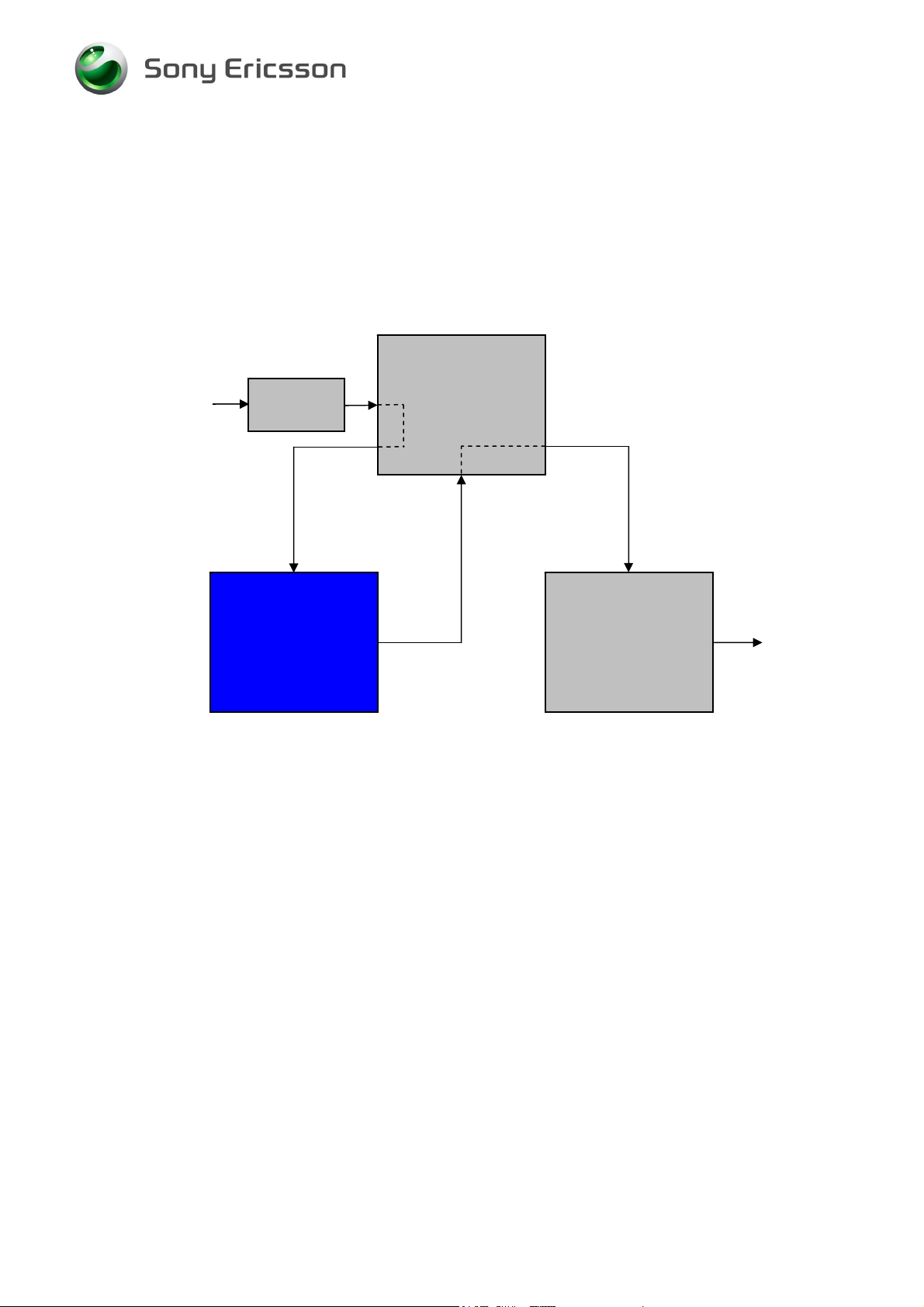
2 Disassembly
When you are going to replace a part being listed in Replacements, the instruction of that section
usually begins by directing you to this Disassembly section with a specification of the instructions you
have to carry out in order to disassemble the phone as far as needed before returning to
Replacements for the actual replacement.
REPLACEMENTS
Start
Contents
page
DISASSEMBLY
REASSEMBLY
Done
3/000 21-1/FEA 209 544/115 C
Company Internal
© Sony Ericsson Mobile Communications AB
6(64)
Page 7
r
Working Instruction, Mechanical
2.1 Lower unit
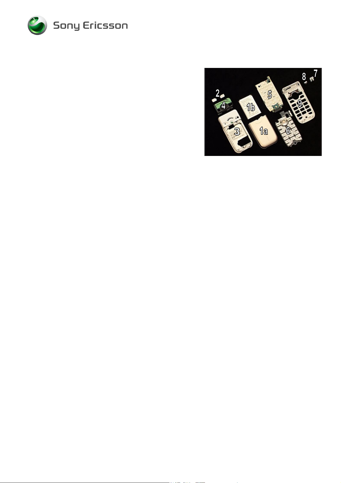
The disassembly is done in the following order:
1. Battery Cover (a) & Battery (b)
2. Screw Covers (not to be reused)
3. Lower Outer Cover
4. Speaker Box
5. PCBA
6. Keypad
7. Side Ring Strap
8. Side Ring
9. Lower Inner Cove
3/000 21-1/FEA 209 544/115 C
Company Internal
© Sony Ericsson Mobile Communications AB
7(64)
Page 8
Working Instruction, Mechanical
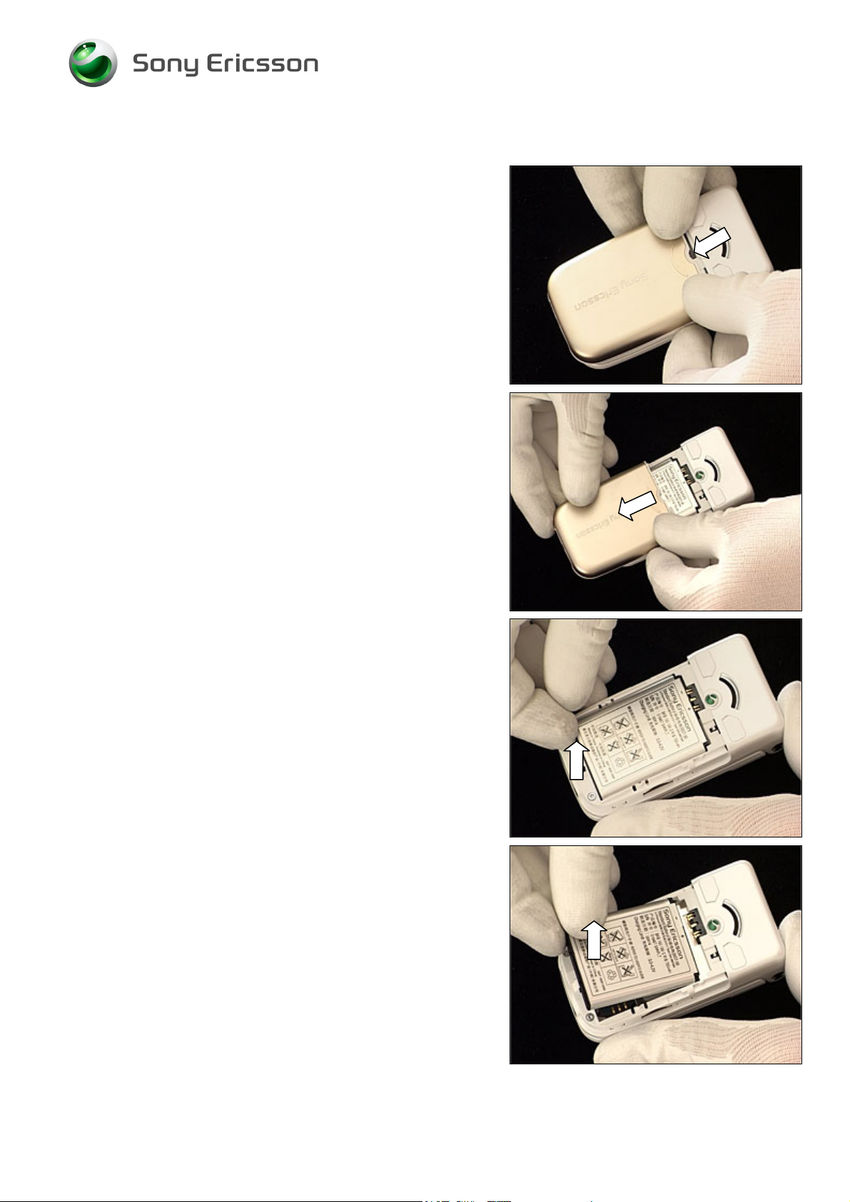
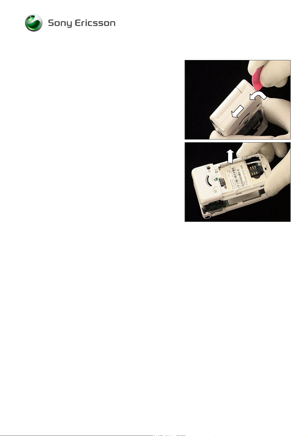
2.1.1 Battery Cover & Battery
Press on top of the battery cover and push it forward to
open up a gap,
and slide it until it becomes released and can be removed.
Put your finger here,
to raise and remove the battery.
3/000 21-1/FEA 209 544/115 C
Company Internal
© Sony Ericsson Mobile Communications AB
8(64)
Page 9
Working Instruction, Mechanical
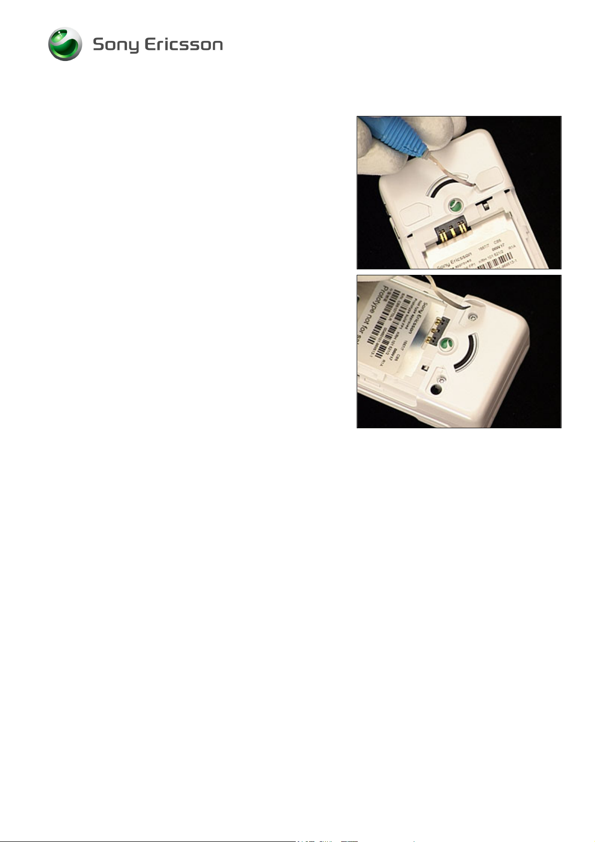
2.1.2 Screw Covers
Carefully insert the dentist hook under one of the screw
covers to have it detached and then removed.
Do the same with the second screw cover.
HE SCREW COVERS CANNOT BE REUSED AND MUST BE
T
SCRAPPED!
3/000 21-1/FEA 209 544/115 C
Company Internal
© Sony Ericsson Mobile Communications AB
9(64)
Page 10
Working Instruction, Mechanical
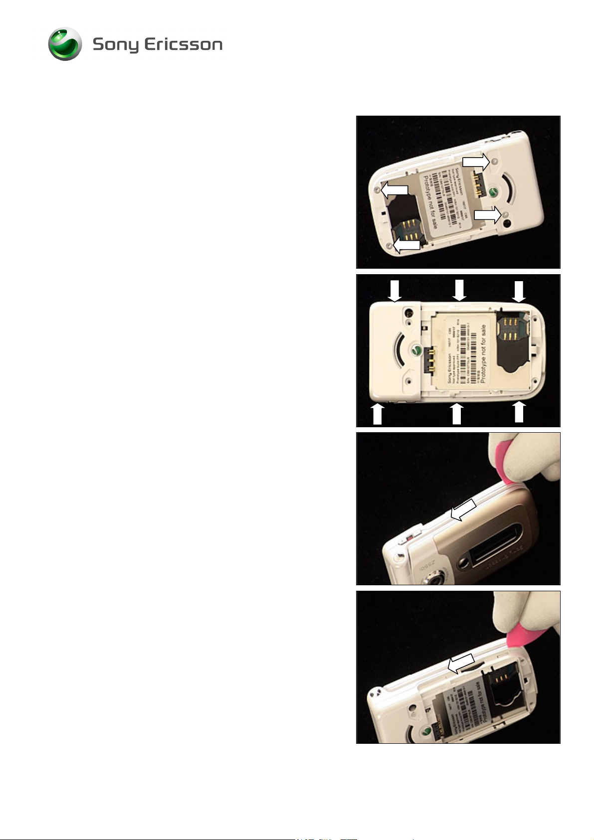
2.1.3 Lower Outer Cover
Use torx bit no. 6 to remove these four screws.
There are six snap hooks located here that have to be
unlatched.
Insert the guitar pick as shown in picture and slide it along
this side towards the hinge to unlatch the three snap hooks.
If necessary, slide back and forth until all three hooks are
unlatched.
Do the same on the opposite side.
3/000 21-1/FEA 209 544/115 C
Company Internal
© Sony Ericsson Mobile Communications AB
10(64)
Page 11
Working Instruction, Mechanical
Lower Outer Cover continued
Insert the guitar pick at the position of the hinge (as shown
in picture) and slide it round the corner towards the opposite
corner to open up a gap.
Carefully lift off the lower outer cover.
3/000 21-1/FEA 209 544/115 C
Company Internal
© Sony Ericsson Mobile Communications AB
11(64)
Page 12
Working Instruction, Mechanical
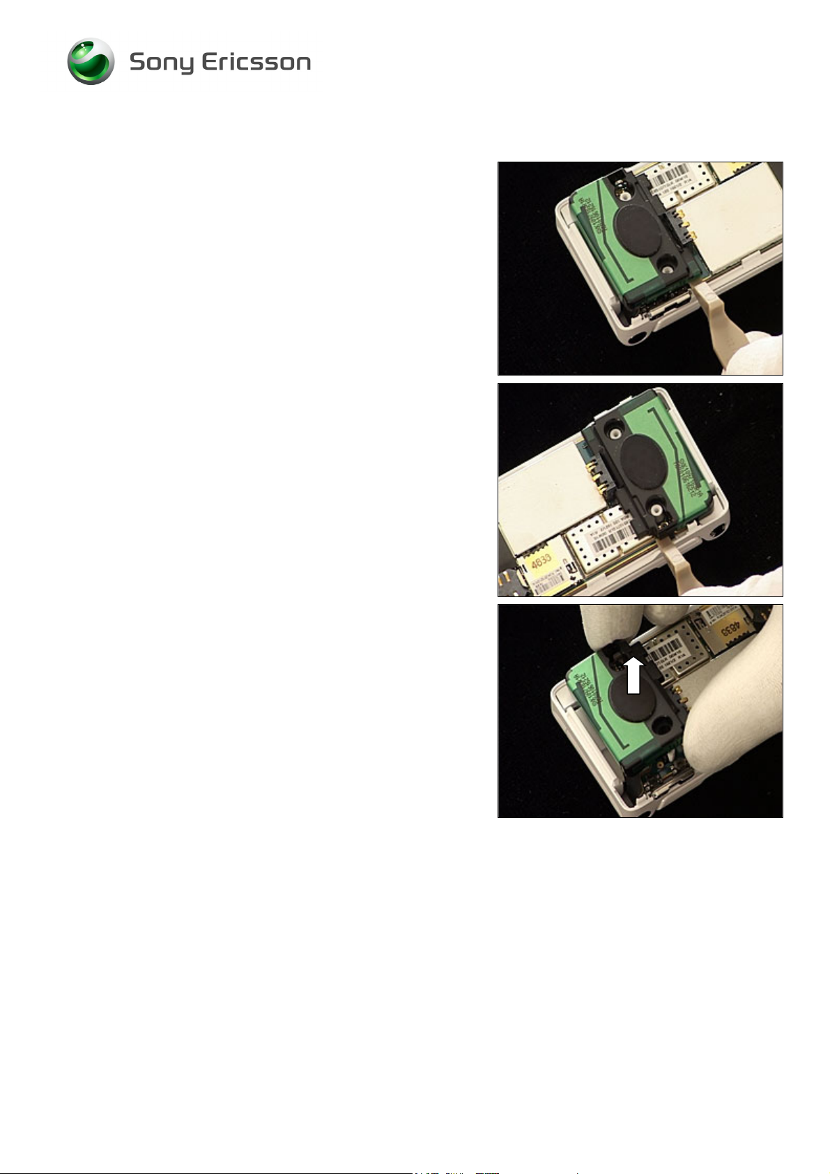
2.1.4 Speaker Box
Insert the front opening tool and release the speaker box
from the PBA on this side.
Do the same on the opposite side.
Remove the speaker box.
3/000 21-1/FEA 209 544/115 C
Company Internal
© Sony Ericsson Mobile Communications AB
12(64)
Page 13
Working Instruction, Mechanical
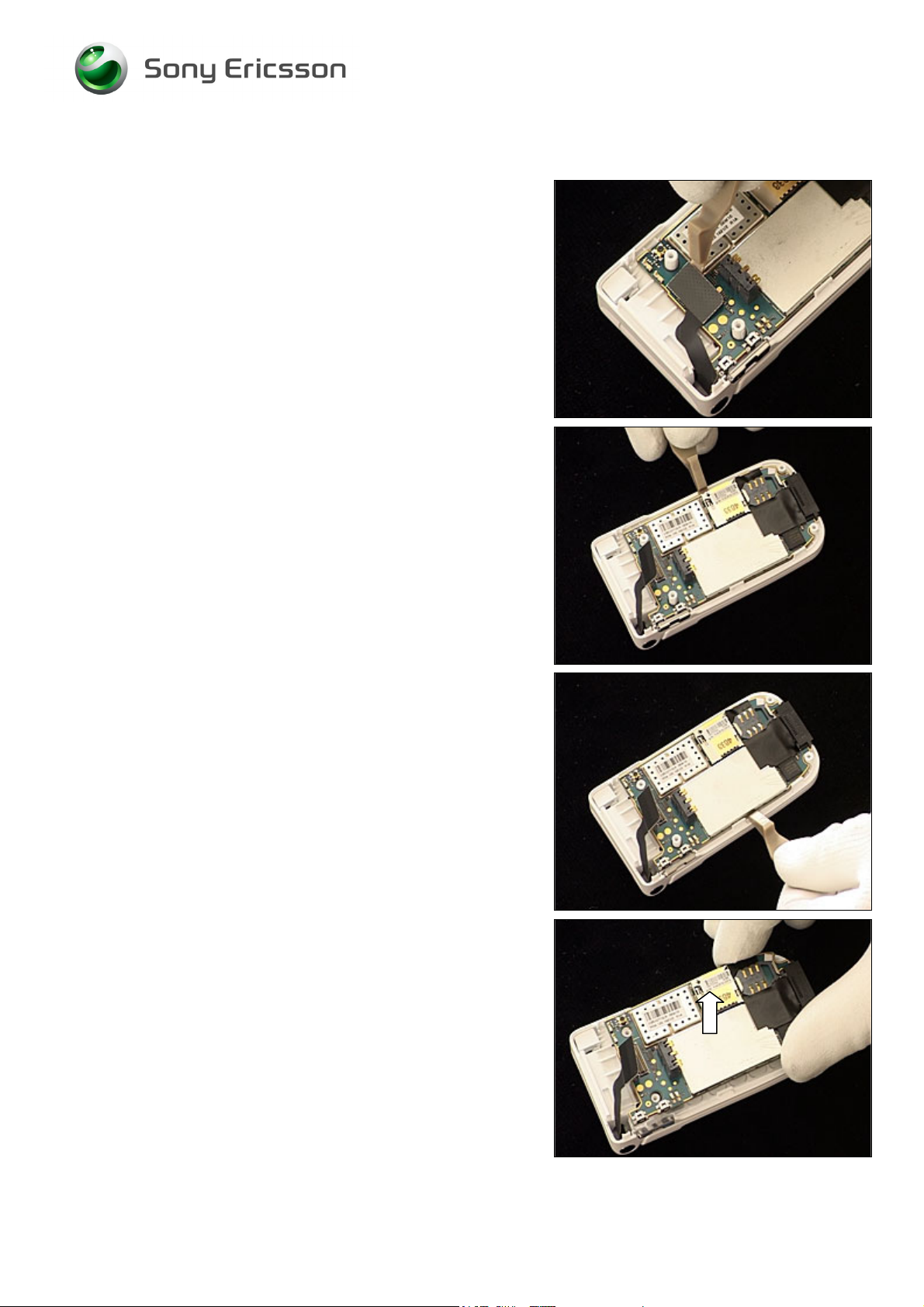
2.1.5 PCBA
Disconnect the board-to-board connector with the front
opening tool (see picture page 5).
Release the PCBA from the lower inner cover with the front
opening tool.
Do the same on the opposite side.
Remove the PCBA.
3/000 21-1/FEA 209 544/115 C
Company Internal
© Sony Ericsson Mobile Communications AB
13(64)
Page 14
Working Instruction, Mechanical
2.1.6 Keypad
Remove the keypad with the tweezers or by hand.
3/000 21-1/FEA 209 544/115 C
Company Internal
© Sony Ericsson Mobile Communications AB
14(64)
Page 15
Working Instruction, Mechanical
2.1.7 Side Ring Strap
Use the front opening tool to raise the side ring strap from
its position,
and remove it with the tweezers.
3/000 21-1/FEA 209 544/115 C
Company Internal
© Sony Ericsson Mobile Communications AB
15(64)
Page 16
Working Instruction, Mechanical
2.1.8 Side Ring
Use the dentist hook or the tweezers to push the side ring
out of its hole,
and remove it with the tweezers
3/000 21-1/FEA 209 544/115 C
Company Internal
© Sony Ericsson Mobile Communications AB
16(64)
Page 17
Working Instruction, Mechanical
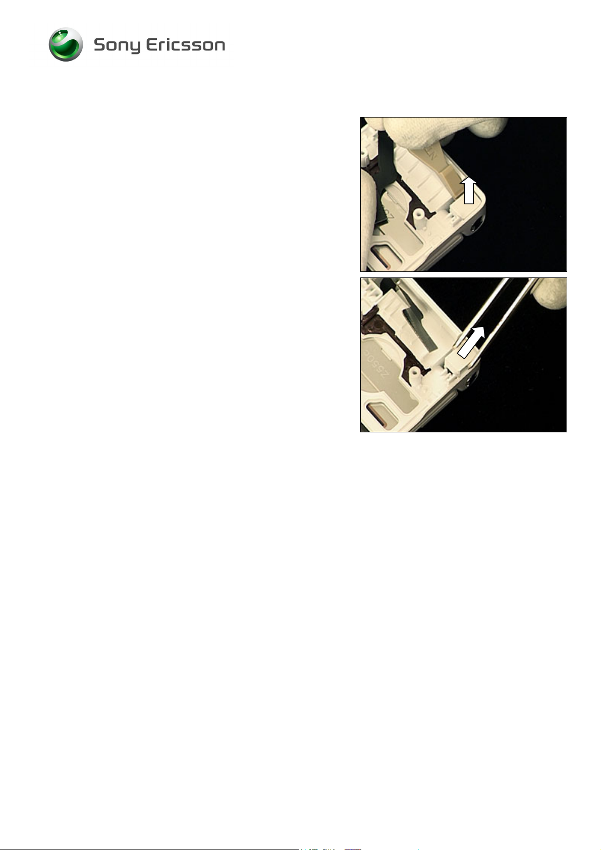
2.1.9 Lower Inner Cover
This is the hinge which can be moved inwards like a spring.
Press the hinge inwards with the tweezers (1) and at the
same time move the lower inner cover in the direction of the
arrow (2),
until the lower inner cover is released from the hinge.
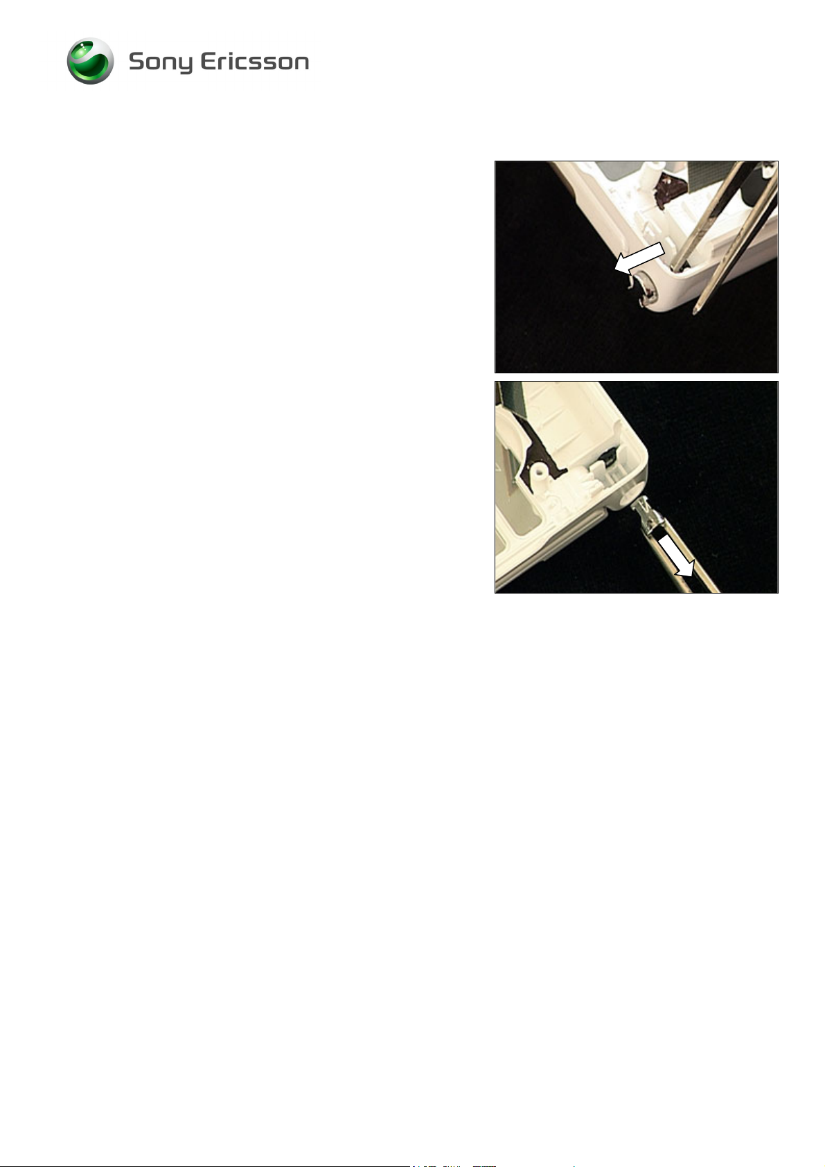
Continue to push,
until the lower inner cover is separated from the upper unit.
3/000 21-1/FEA 209 544/115 C
Company Internal
© Sony Ericsson Mobile Communications AB
17(64)
Page 18
Working Instruction, Mechanical
Lower Inner Cover continued
Slide the flex film out of the hole of the lower inner cover,
to make it completely separated from the upper unit.
3/000 21-1/FEA 209 544/115 C
Company Internal
© Sony Ericsson Mobile Communications AB
18(64)
Page 19
Working Instruction, Mechanical
2.2 Upper unit
The disassembly is done in the following order:
1. Co-Brand Screw Covers (not to be reused)
2. Upper Outer Cover
3. Upper Inner Cover
3/000 21-1/FEA 209 544/115 C
Company Internal
© Sony Ericsson Mobile Communications AB
19(64)
Page 20
Working Instruction, Mechanical
2.2.1 Co-Brand Screw Covers
BE CAREFUL NOT TO DAMAGE THE UPPER INNER COVER
DURING THIS OPERATION
Use the tweezers and/or the dentist hook to release and
remove the first of the two screw covers.
!
Insert the tweezers or the dentist hook through the hole of
this screw cover as shown in picture to release and remove
it.
T
HE CO-BRAND SCREW COVERS CANNOT BE REUSED AND
MUST BE SCRAPPED
!
3/000 21-1/FEA 209 544/115 C
Company Internal
© Sony Ericsson Mobile Communications AB
20(64)
Page 21

Working Instruction, Mechanical
2.2.2 Upper Outer Cover
Use torx bit no. 6 to remove these four screws.
Insert the guitar pick as shown in picture and slide it in the
direction of the arrow to release the upper outer cover on
this side.
Insert the guitar pick in the gap and slide it around the
corner towards the opposite corner to release the upper
outer cover at the top.
Continue to slide the guitar pick around this corner all the
way down to the end of the cover.
3/000 21-1/FEA 209 544/115 C
Company Internal
© Sony Ericsson Mobile Communications AB
21(64)
Page 22

Working Instruction, Mechanical
Upper Outer Cover continued
Lift the upper outer cover at the top (1) and gently wiggle it
side to side (2) until it is released at the hinge section (3),
and can be removed.
3/000 21-1/FEA 209 544/115 C
Company Internal
© Sony Ericsson Mobile Communications AB
22(64)
Page 23

Working Instruction, Mechanical
2.2.3 Upper Inner Cover
Unsnap the LCD frame from the upper inner cover with the
front opening tool on this side.
Do the same on the opposite side
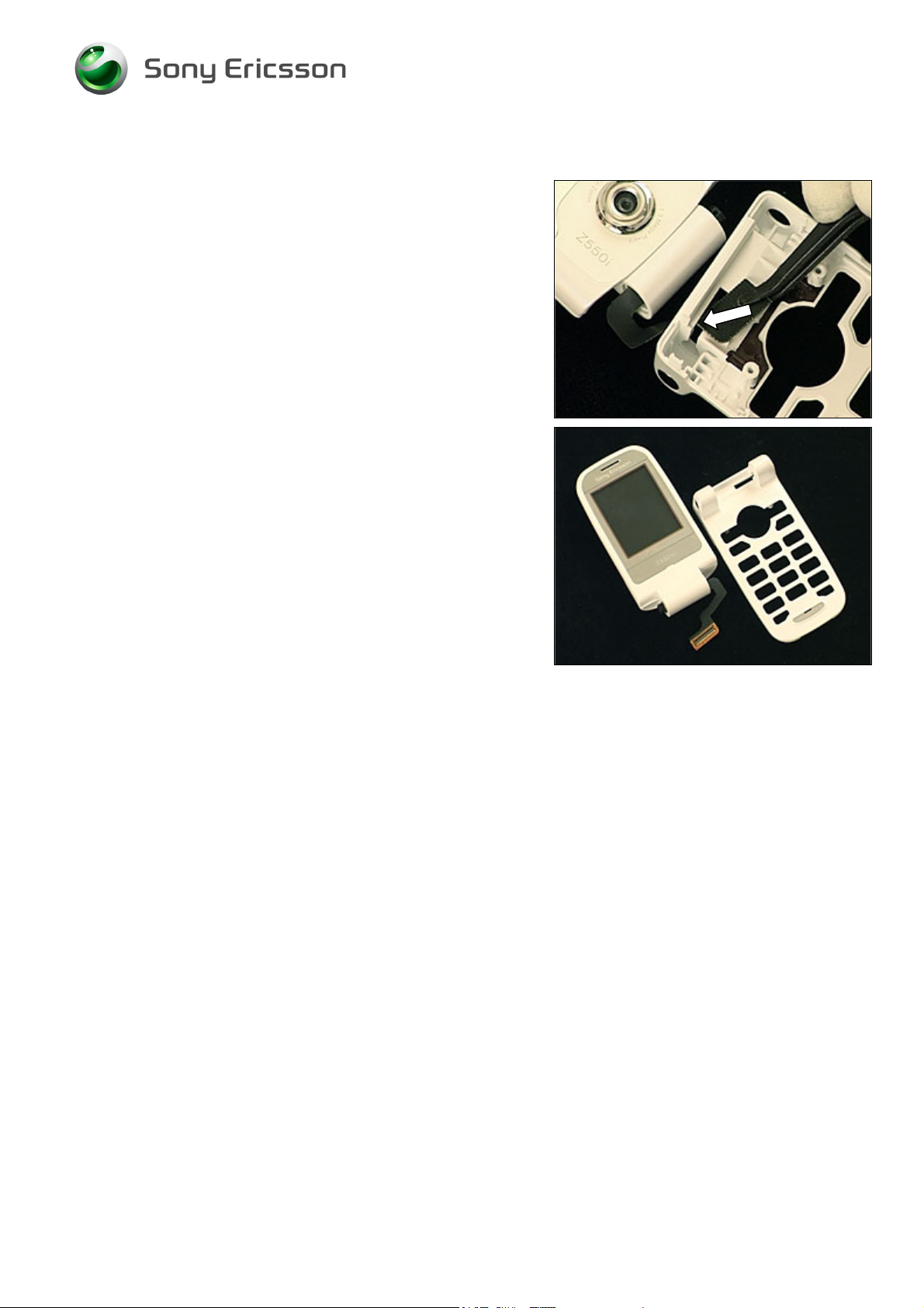
Lift the LCD frame at the top (1) and move it in the direction
of the arrow (2),
to make the flex film smoothly slide out of the hinge section,
3/000 21-1/FEA 209 544/115 C
Company Internal
© Sony Ericsson Mobile Communications AB
23(64)
Page 24

Working Instruction, Mechanical
Upper Inner Cover continued
to have them completely separated.
3/000 21-1/FEA 209 544/115 C
Company Internal
© Sony Ericsson Mobile Communications AB
24(64)
Page 25

Working Instruction, Mechanical
3 Replacements
Search for the part to be replaced on the Contents page and go to that instruction to be found in this
Replacements section.
The instruction usually begins by directing you to the Disassembly section with a specification of the
instructions you have to carry out in order to disassemble the phone as far as needed before the
actual replacement.
Go back to this Replacements section and carry out the instruction.
The instruction usually ends by directing you to the Reassembly section with a specification of the
instructions you have to carry out in order to reassemble the phone.
REPLACEMENTS
Start
Contents
page
DISASSEMBLY REASSEMBLY
Done
3/000 21-1/FEA 209 544/115 C
Company Internal
© Sony Ericsson Mobile Communications AB
25(64)
Page 26

Working Instruction, Mechanical
3.1 Battery Cover
Follow the 2.1.1 Disassembly instructions!
Prepare the new battery cover.
Follow the 4.2.8 Reassembly instructions!
3.2 Screw Covers
Follow the 2.1.2 Disassembly instructions!
Prepare the new screw covers.
Follow the 4.2.7 Reassembly instructions!
3.3 Lower Outer Cover
Follow the 2.1.1 – 2.1.3 Disassembly instructions!
Prepare the new lower outer cover.
Follow the 4.2.6 – 4.2.8 Reassembly instructions!
3.4 Speaker Box
Follow the 2.1.1 – 2.1.4 Disassembly instructions!
Prepare the new speaker box.
Follow the 4.2.5 – 4.2.8 Reassembly instructions!
3.5 Side Ring Strap
Follow the 2.1.1 – 2.1.7 Disassembly instructions!
Prepare the new side ring strap.
Follow the 4.2.2. – 4.2.8 Reassembly instructions!
3.6 Side Ring
Follow the 2.1.1 – 2.1.8 Disassembly instructions!
Prepare the new side ring.
Follow the 4.2.1 – 4.2.8 Reassembly instructions!
3.7 Lower Inner Cover
Follow the 2.1.1 – 2.2.2 Disassembly instructions!
Prepare the new lower inner cover.
Follow the 4.1.2 –4.2.8 Reassembly instructions!
3/000 21-1/FEA 209 544/115 C
Company Internal
© Sony Ericsson Mobile Communications AB
26(64)
Page 27

Working Instruction, Mechanical
3.8 Co-Brand Screw Covers
Follow the 2.2.1 Disassembly instructions!
Prepare the new co-brand screw covers.
Follow the 4.1.4 Reassembly instructions!
3.9 Upper Outer Cover
Follow the 2.2.1 – 2.2.2 Disassembly instructions!
Prepare the new upper outer cover.
Follow the 4.1.2 – 4.1.4 Reassembly instructions!
3.10 Upper Inner Cover
Follow the 2.1.1 –2.2.3 Disassembly instructions!
Prepare the new upper inner cover.
Follow the 4.1.1 –4.2.8 Reassembly instructions!
3/000 21-1/FEA 209 544/115 C
Company Internal
© Sony Ericsson Mobile Communications AB
27(64)
Page 28

Working Instruction, Mechanical
3.11 Dual LCD
REMOVAL
Follow the 2.1.1 –2.2.3 Disassembly instructions!
Use the front opening tool to release the LCD from its
frame.
Turn the LCD like this to get access to the FPC-connector.
(see picture on page 5 regarding FPC connectors)
Unlock the FPC-connector with the dentist hook,
and remove the flex film with the flex film assembly tool,
3/000 21-1/FEA 209 544/115 C
Company Internal
© Sony Ericsson Mobile Communications AB
28(64)
Page 29

Working Instruction, Mechanical
Dual LCD continued
to be able to separate the dual LCD from the LCD frame.
INSTALLATION
Place the flex film connector (1) and FPC-connector (2)
next to each other.
Turn the LCD and the LCD frame against each other so that
the flex film can be inserted into the FPC-connector with the
flex film assembly tool.
Lock the FPC-connector by turning the black bar with the
flex film assembly tool,
3/000 21-1/FEA 209 544/115 C
Company Internal
© Sony Ericsson Mobile Communications AB
29(64)
Page 30

Working Instruction, Mechanical
Dual LCD continued
like this.
Put the LCD into its frame and press on the corners to
secure its position.
Follow the 4.1.1 – 4.2.8 Reassembly instructions!
3/000 21-1/FEA 209 544/115 C
Company Internal
© Sony Ericsson Mobile Communications AB
30(64)
Page 31

Working Instruction, Mechanical
3.12 Main FPC
REMOVAL
Follow the 2.1.1 –2.2.3 Disassembly instructions!
Follow the 3.11 Removal instructions!
Loosen the vibrator support with the tweezers,
and remove it.
Insert the front opening tool at the top underneath the metal
plate to release the main FPC.
Make sure the metal plate is removed together with the
main FPC.
3/000 21-1/FEA 209 544/115 C
Company Internal
© Sony Ericsson Mobile Communications AB
31(64)
Page 32

Working Instruction, Mechanical
Main FPC continued
Remove the main FPC.
INSTALLATION
Place the main FPC like this.
Put the top part of the main FPC in its proper place with the
help of the guiding hole of the main FPC and the guiding
peg of the LCD frame (1) and then press (2) with your finger
to secure the attachment.
Gently push the camera into the bottom of its cavity.
3/000 21-1/FEA 209 544/115 C
Company Internal
© Sony Ericsson Mobile Communications AB
32(64)
Page 33

Working Instruction, Mechanical
Main FPC continued
Put the vibrator support on top of the FPC contacts for the
vibrator,
and press to secure its position.
Follow the 3.11 Installation instructions!
Follow the 4.1.1 – 4.2.8 Reassembly instructions!
3/000 21-1/FEA 209 544/115 C
Company Internal
© Sony Ericsson Mobile Communications AB
33(64)
Page 34

Working Instruction, Mechanical
3.13 Camera
REMOVAL
Follow the 2.1.1 –2.2.3 Disassembly instructions!
Follow the 3.11 & 3.12 Removal instructions!
Keep the camera removal tool in this position when the
camera orientation is as shown in the picture.
Push the tool to the bottom of the camera socket (1).
Then pull it out of the socket (2).
Remove the camera by lifting straight up.
INSTALLATION
NOTE THE ORIENTATION OF CAMERA AND SOCKET:
CAMERA PEG (1) INTO SOCKET NOTCH (2)!
Place the camera in its proper position on top of the socket.
3/000 21-1/FEA 209 544/115 C
Company Internal
© Sony Ericsson Mobile Communications AB
34(64)
Page 35

Working Instruction, Mechanical
Camera continued
DO NOT TOUCH THE CAMERA LENS!
Press on the black camera case (1) outside the camera
lens (2) until the camera has reached the bottom of the
socket.
Follow the 3.12 & 3.11 Installation instructions!
Follow the 4.1.1 – 4.2.8 Reassembly instructions!
3/000 21-1/FEA 209 544/115 C
Company Internal
© Sony Ericsson Mobile Communications AB
35(64)
Page 36

Working Instruction, Mechanical
3.14 Vibrator & Vibrator Support
REMOVAL
Follow the 2.1.1 – 2.2.3 Disassembly instructions!
Loosen the vibrator support with the tweezers,
and remove it.
Use the dentist hook to raise the vibrator out of its cavity,
and remove it with the tweezers.
3/000 21-1/FEA 209 544/115 C
Company Internal
© Sony Ericsson Mobile Communications AB
36(64)
Page 37

Working Instruction, Mechanical
Vibrator & Vibrator Support continued
INSTALLATION
Place the vibrator in the cavity,
and press it down to the bottom without touching the
contact springs.
Put the vibrator support on top of the FPC contacts for the
vibrator,
and press to secure its position.
Follow the 4.1.1 – 4.2.8 Reassembly instructions!
3/000 21-1/FEA 209 544/115 C
Company Internal
© Sony Ericsson Mobile Communications AB
37(64)
Page 38

Working Instruction, Mechanical
3.15 Magnet
REMOVAL
Follow the 2.1.1 – 2.2.3 Disassembly instructions!
Press from behind with the tweezers to release and remove
the magnet.
INSTALLATION
If necessary, first clean the cavity with isopropyl alcohol.
N
OTE THE ORIENTATION OF THE RED LINE ON THE MAGNET!
Use the tweezers to mount the magnet and press for a few
seconds to secure the attachment.
Follow the 4.1.1 – 4.2.8 Reassembly instructions!
3/000 21-1/FEA 209 544/115 C
Company Internal
© Sony Ericsson Mobile Communications AB
38(64)
Page 39

Working Instruction, Mechanical
3.16 Receiver
REMOVAL
Follow the 2.1.1 – 2.2.3 Disassembly instructions!
Use the dentist hook to raise the receiver out of its cavity.
Then remove it with the tweezers.
E CAREFUL NOT TO DAMAGE THE COPPER FOIL LOCATED
B
UNDERNEATH THE RECEIVER
.
INSTALLATION
Place the receiver in the cavity,
and press it down to the bottom without touching the
contact springs.
Follow the 4.1.1 – 4.2.8 Reassembly instructions!
3/000 21-1/FEA 209 544/115 C
Company Internal
© Sony Ericsson Mobile Communications AB
39(64)
Page 40

Working Instruction, Mechanical
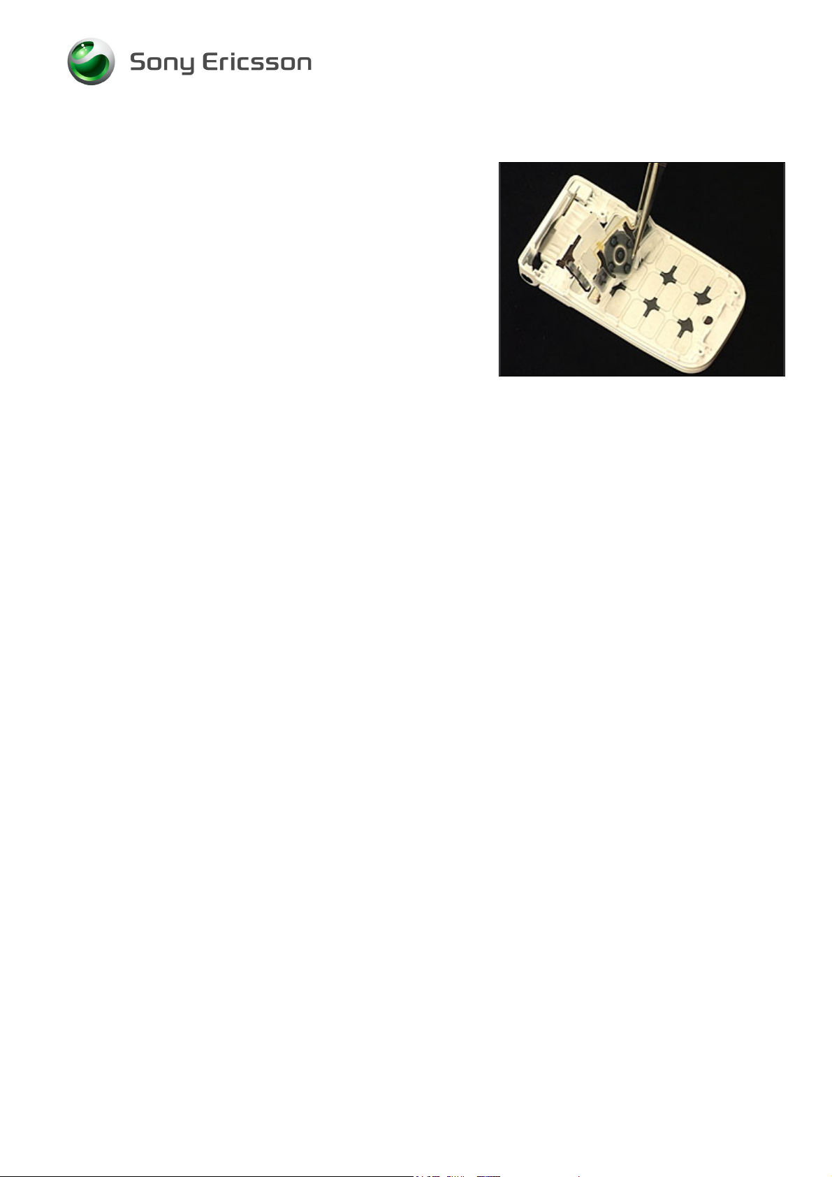
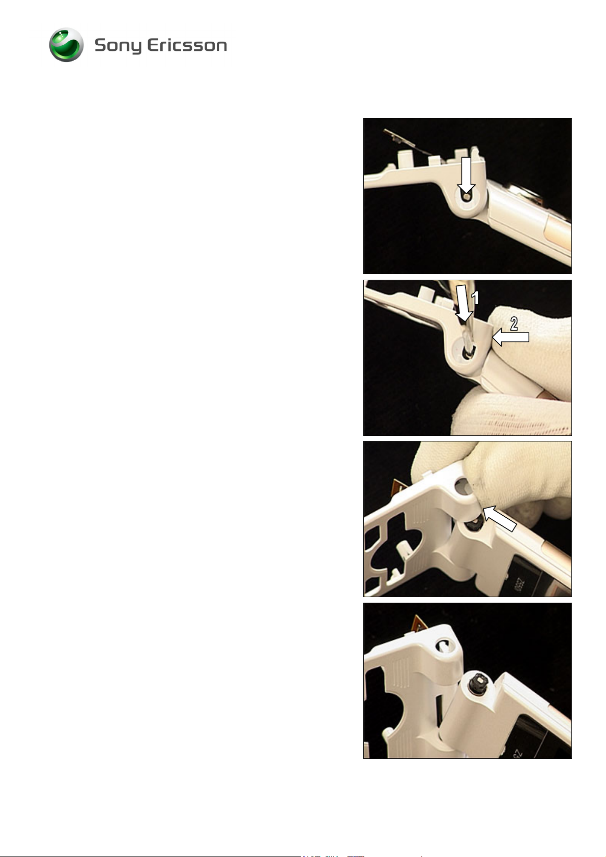
3.17 Hinge
REMOVAL
Follow the 2.1.1 – 2.2.3 Disassembly instructions!
Press with the tweezers through the hole of the hinge
section,
until the hinge falls out.
INSTALLATION
Note the shape of the hole where the hinge will be inserted.
Insert the hinge like this.
3/000 21-1/FEA 209 544/115 C
Company Internal
© Sony Ericsson Mobile Communications AB
40(64)
Page 41

Working Instruction, Mechanical
Hinge continued
Press on the hinge as far as it goes.
Follow the 4.1.1 – 4.2.8 Reassembly instructions!
3/000 21-1/FEA 209 544/115 C
Company Internal
© Sony Ericsson Mobile Communications AB
41(64)
Page 42

Working Instruction, Mechanical
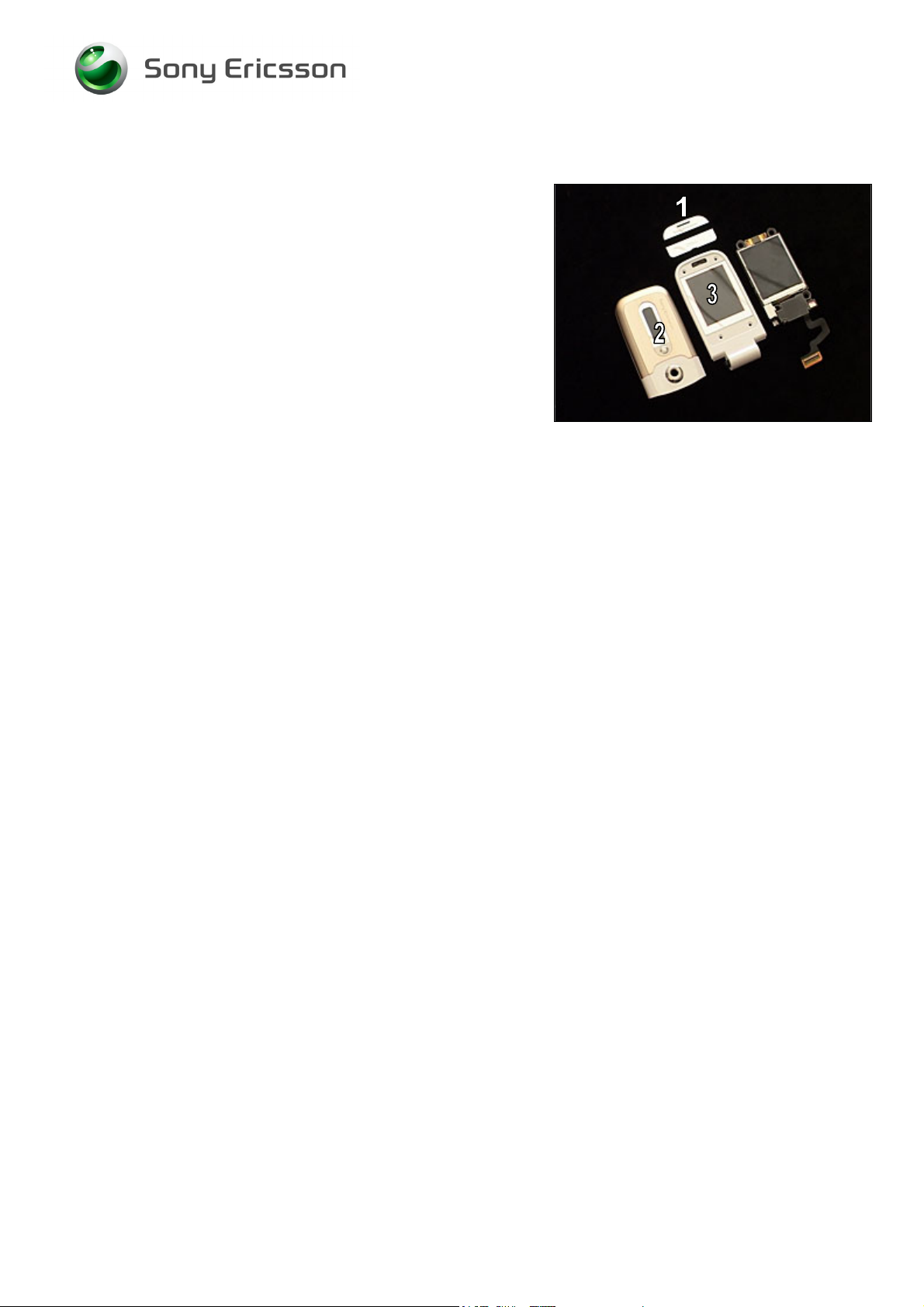
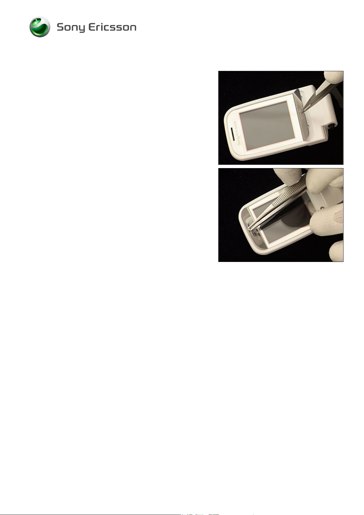
3.18 Sub Display Window
REMOVAL
Follow the 2.2.1 – 2.2.2 Disassembly instructions!
D
O NOT USE EXCESSIVE FORCE WHEN PRESSING ON THE
DISPLAY WINDOW AS IT MIGHT BREAK!
Carefully press with your finger from the inside on the sub
display window until it becomes released from the upper
outer cover,
and remove it.
INSTALLATION
Place the sub display window like this,
and press to secure a good attachment.
Follow the 4.1.3 – 4.1.4 Reassembly instructions!
3/000 21-1/FEA 209 544/115 C
Company Internal
© Sony Ericsson Mobile Communications AB
42(64)
Page 43

Working Instruction, Mechanical
3.19 Electric Cloths
There is under normal circumstances no need to remove an
electric cloth for replacement.
There are two electric cloths on the inside of the upper
outer cover,
and four on the LCD frame.
In case an electric cloth is missing, use the tweezers and
your fingers to attach a new one.
3/000 21-1/FEA 209 544/115 C
Company Internal
© Sony Ericsson Mobile Communications AB
43(64)
Page 44

Working Instruction, Mechanical
3.20 Dome Sheet Array
REMOVAL
Follow the 2.1.1– 2.1.5 Disassembly instructions!
Use the tweezers to peel off the dome sheet array from the
PBA.
INSTALLATION
Clean the PBA surface with isopropyl alcohol.
Make sure that the two guiding holes on the PBA
correspond to the two holes on the dome sheet array,
when attaching the new dome sheet array,
in a proper way.
Follow the 4.2.4 – 4.2.8 Reassembly instructions!
3/000 21-1/FEA 209 544/115 C
Company Internal
© Sony Ericsson Mobile Communications AB
44(64)
Page 45

Working Instruction, Mechanical
3.21 System Connector
REMOVAL
Follow the 2.1.1 – 2.1.5 Disassembly instructions!
Remove the system connector by pulling it from the PBA.
INSTALLATION
OTE THE ORIENTATION OF THE SYSTEM CONNECTOR!
N
Push and press the system connector onto the PBA as far
as it goes.
Follow the 4.2.4 – 4.2.8 Reassembly instructions!
3/000 21-1/FEA 209 544/115 C
Company Internal
© Sony Ericsson Mobile Communications AB
45(64)
Page 46

Working Instruction, Mechanical
3.22 Liquid Intrusion Indicator
INSPECTION
To check whether the liquid intrusion indicator has been
activated or not, just remove the battery cover and the
battery.
REMOVAL
Follow the 2.1.1 – 2.1.5 Disassembly instructions!
Remove the activated liquid intrusion indicator with the
dentist hook and the tweezers.
INSTALLATION
Attach the new liquid intrusion indicator with the tweezers
and your fingers.
Follow the 4.2.4 – 4.2.8 Reassembly instructions!
3/000 21-1/FEA 209 544/115 C
Company Internal
© Sony Ericsson Mobile Communications AB
46(64)
Page 47

Working Instruction, Mechanical
3.23 Label
Follow the 2.1.1 Disassembly instructions!
• Read the old label and/or write the information into the
“Label make” program before removal
• Note the position of the label before removal
• Heat up the label by using hot air, if needed
• Carefully remove the label without causing scratches
• If there still are residues, clean the surface with isopropyl
alcohol
• Check that the proper label format is loaded in the Zebra
printer
• Write a new label by using the program “Label make”
and check that the printing is OK
• Take the new label and place it onto the frame as in the
adjacent picture
O
NE LABEL ONLY IS ALLOWED!
Follow the 4.2.8 Reassembly instructions!
3/000 21-1/FEA 209 544/115 C
Company Internal
© Sony Ericsson Mobile Communications AB
47(64)
Page 48

Working Instruction, Mechanical
4 Reassembly
After replacing a part being listed in Replacements, the instruction of that section usually ends by
directing you to this Reassembly section with a specification of the instructions you have to carry out
in order to reassemble the phone.
REPLACEMENTS
Start
Contents
page
DISASSEMBLY
REASSEMBLY
Done
3/000 21-1/FEA 209 544/115 C
Company Internal
© Sony Ericsson Mobile Communications AB
48(64)
Page 49

Working Instruction, Mechanical
4.1 Upper unit
The reassembly is done in the following order:
1. Upper Inner Cover
2. Lower Inner Cover
3. Upper Outer Cover
4. Co-brand Screw Covers
3/000 21-1/FEA 209 544/115 C
Company Internal
© Sony Ericsson Mobile Communications AB
49(64)
Page 50

Working Instruction, Mechanical
4.1.1 Upper Inner Cover
Hold the LCD frame in a slight vertical angle and move it (1)
to slide the flex film through the slot (2) of the hinge section.
and at the same time push it against the hinge section
Press on the LCD frame to secure it to the upper inner
cover.
3/000 21-1/FEA 209 544/115 C
Company Internal
© Sony Ericsson Mobile Communications AB
50(64)
Page 51

Working Instruction, Mechanical
4.1.2 Lower Inner Cover
Insert the flex film through the hole of the lower inner cover,
and then insert the flex film through the small slot of the
lower inner cover.
Place one end of the hinge section against the lower inner
cover,
and press with your thumb (1) and place the opposite end
of the hinge section as shown by the arrow (2).
3/000 21-1/FEA 209 544/115 C
Company Internal
© Sony Ericsson Mobile Communications AB
51(64)
Page 52

Working Instruction, Mechanical
Lower Inner Cover continued
Press the hinge inwards (1) with the tweezers and at the
same time push (2) the lower inner cover in the direction of
the arrow,
to make them properly joined.
3/000 21-1/FEA 209 544/115 C
Company Internal
© Sony Ericsson Mobile Communications AB
52(64)
Page 53

Working Instruction, Mechanical
4.1.3 Upper Outer Cover
Hold the upper outer cover in a slight angle and snap it to
the inner outer cover at the hinge section,
and then snap the remaining sides until the two covers are
joined without any gaps.
Use 20 Ncm torque when tightening the four screws with
torx bit no. 6.
3/000 21-1/FEA 209 544/115 C
Company Internal
© Sony Ericsson Mobile Communications AB
53(64)
Page 54

Working Instruction, Mechanical
4.1.4 Co-Brand Screw Covers
Clean the cavities with isopropyl alcohol.
SE NEW CO-BRAND SCREW COVERS!
U
Use the tweezers and your fingers to attach the first
co-brand screw cover,
and then the second one,
like this.
3/000 21-1/FEA 209 544/115 C
Company Internal
© Sony Ericsson Mobile Communications AB
54(64)
Page 55

Working Instruction, Mechanical
4.2 Lower unit
The reassembly is done in the following order:
1. Side Ring
2. Side Ring Strap
3. Keypad
4. PBA
5. Speaker Box
6. Lower Outer Cover
7. Screw Covers
8. Battery (a) & Battery Cover (b)
3/000 21-1/FEA 209 544/115 C
Company Internal
© Sony Ericsson Mobile Communications AB
55(64)
Page 56

Working Instruction, Mechanical
4.2.1 Side Ring
NOTE THE ORIENTATION OF THE SIDE RING!
T
HIS PICTURE SHOWS THE “INWARD” SIDE OF THE SIDE RING,
AND THE ARROW POINTS AT THE PART TO BE INSERTED INTO
THE BOTTOM OF THE CAVITY!
Insert the side ring through the hole of the lower inner cover
with the tweezers.
3/000 21-1/FEA 209 544/115 C
Company Internal
© Sony Ericsson Mobile Communications AB
56(64)
Page 57

Working Instruction, Mechanical
4.2.2 Side Ring Strap
Insert the side ring strap with the tweezers,
and press to secure its position.
3/000 21-1/FEA 209 544/115 C
Company Internal
© Sony Ericsson Mobile Communications AB
57(64)
Page 58

Working Instruction, Mechanical
4.2.3 Keypad
Mount the keypad in its proper position with the tweezers
and your fingers
and place this part of the keypad into its slots.
3/000 21-1/FEA 209 544/115 C
Company Internal
© Sony Ericsson Mobile Communications AB
58(64)
Page 59

Working Instruction, Mechanical
4.2.4 PBA
Place the PBA onto the two guiding pins of the lower inner
cover,
and press to secure its position.
Connect the board-to-board connector,
like this.
3/000 21-1/FEA 209 544/115 C
Company Internal
© Sony Ericsson Mobile Communications AB
59(64)
Page 60

Working Instruction, Mechanical
4.2.5 Speaker Box
The hooks on the speaker box are used for guidance only
and can still be used even if damaged.
Put the speaker box in position on the PBA,
and press on both sides to make it snap.
3/000 21-1/FEA 209 544/115 C
Company Internal
© Sony Ericsson Mobile Communications AB
60(64)
Page 61

Working Instruction, Mechanical
4.2.6 Lower Outer Cover
First snap the upper outer cover to the inner outer cover at
the hinge section,
and then snap the remaining sides until the two covers are
joined without any gaps.
Use 20 Ncm torque to tighten the four screws with torx bit
no. 6.
3/000 21-1/FEA 209 544/115 C
Company Internal
© Sony Ericsson Mobile Communications AB
61(64)
Page 62

Working Instruction, Mechanical
4.2.7 Screw Covers
Clean the surface with isopropyl alcohol.
U
SE NEW SCREW COVERS!
HE TWO SCREW COVERS ARE NOT IDENTICAL AS INDICATED
T
BY THE ARROWS
!
Use the tweezers to place the first screw cover in its cavity,
and then the second one.
Press with your fingers to secure the attachments.
3/000 21-1/FEA 209 544/115 C
Company Internal
© Sony Ericsson Mobile Communications AB
62(64)
Page 63

Working Instruction, Mechanical
4.2.8 Battery & Battery Cover
Insert the battery and push it towards the top of the phone.
Press it down at the bottom.
Place the battery cover on top of the battery and push
towards the top of the phone,
until the battery cover is latched with no gaps.
3/000 21-1/FEA 209 544/115 C
Company Internal
© Sony Ericsson Mobile Communications AB
63(64)
Page 64

Working Instruction, Mechanical
5 Revision history
Rev. Date Changes / Comments
A 2006-07-06 First release
B 2006-09-28 Z550a Released
C 2006-10-12 Z558 Released
3/000 21-1/FEA 209 544/115 C
Company Internal
© Sony Ericsson Mobile Communications AB
64(64)
 Loading...