

Page 1

Working Instruction, Mechanical
Working Instruction, Mechanical
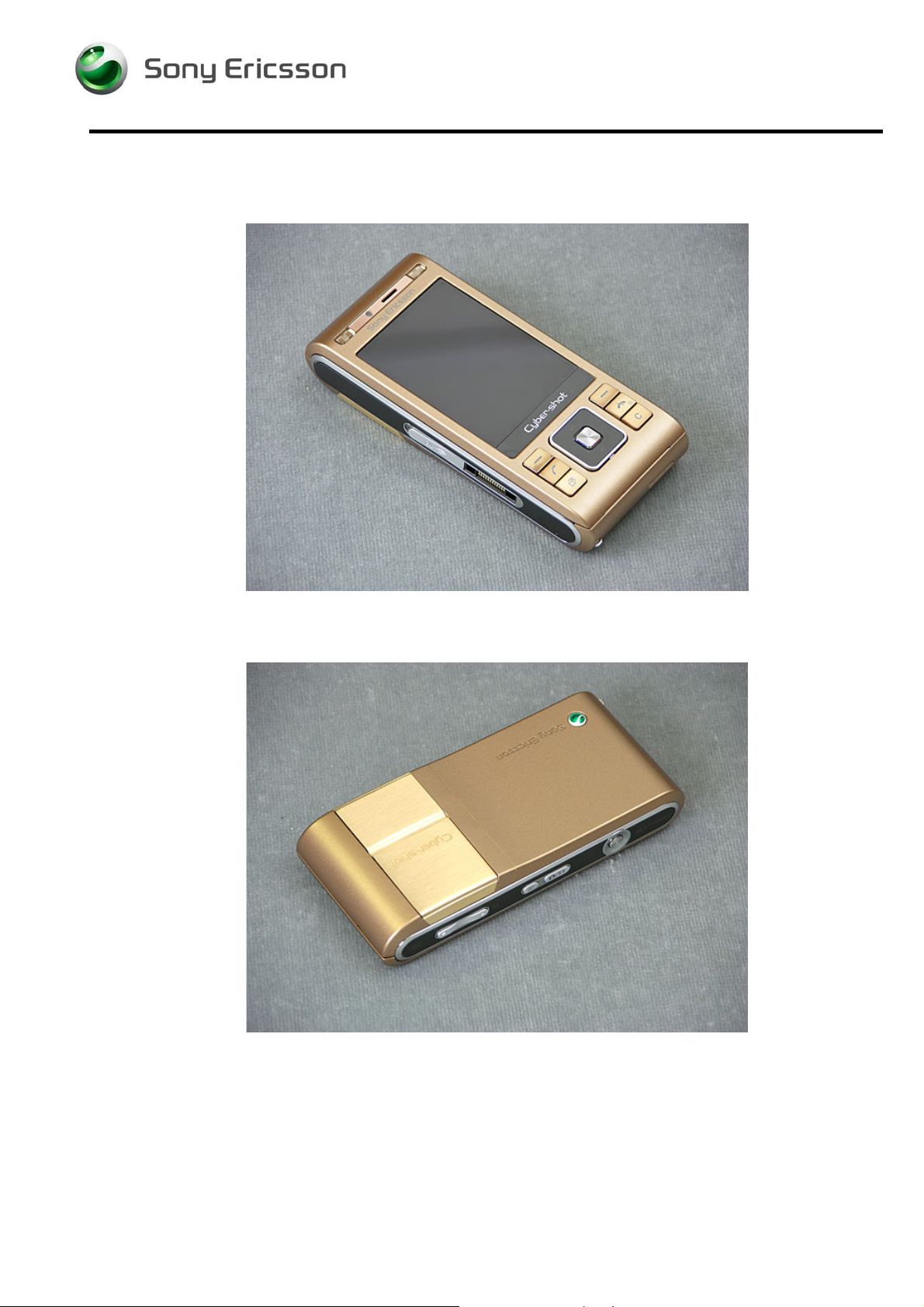
Applicable for C905
CONTENTS
1 Introduction ..............................................................................4
1.1 Equipment.................................................................................5
1.2 General cautions......................................................................6
1.3 Adhesives .................................................................................6
2 Disassembly .............................................................................7
2.1 Overview ...................................................................................8
2.2 Battery Cover & Battery...........................................................9
2.3 Foil Flip Inner..........................................................................10
2.4 Keyboard.................................................................................10
2.5 Cap Plastic RF Numeric Keyboard & Cap Numeric
Keyboard.................................................................................11
2.6 Cover Flip Front......................................................................12
2.7 Display 2.41 TFT.....................................................................13
2.8 LCD Support Sheet ................................................................13
2.9 PBA Key Flex Flip Complete.................................................14
2.10 Cover Rear Assembly............................................................16
2.11 Cover Base Rear Assembly...................................................17
2.12 Main PBA.................................................................................18
2.13 Loudspeaker Assembly.........................................................20
2.14 Flash Complete and Camera 8MP.........................................21
3 Replacements.........................................................................23
3.1 Battery Cover & Battery.........................................................24
3.2 Cover Flip Front Assembly....................................................24
3.3 Cover Base Rear Assembly...................................................24
3.4 Flash Complete.......................................................................24
3.5 PBA Key Flex Flip Complete.................................................24
3.6 Slider FPC Assy......................................................................24
3.7 Cover Rear Assembly............................................................24
3.8 Carrier Base Assembly..........................................................25
3.9 Camera 8 MP...........................................................................25
3.10 Foil Flip Inner..........................................................................25
3.11 LCD Support Sheet ................................................................25
3.12 Loudspeaker Assembly.........................................................25
3.13 Screw 4.0x1.4..........................................................................25
3.14 Screw 2.3x1.4..........................................................................25
1218-1731 Rev 3 1(87)
Company Internal
© Sony Ericsson Mobile Communi cat i ons AB
Page 2

Working Instruction, Mechanical
3.15 Screw Torx 5.3x1.6.................................................................26
3.16 Screw Torx 5.0x1.6.................................................................26
3.17 Screw Philips M1.4x1.7..........................................................26
3.18 Cap Plastic RF Keyboard Numeric.......................................26
3.19 Cap Numeric Keyboard..........................................................26
3.20 Foil Adhesive Single Side 0.15 mm Flip Tape .....................26
3.21 Display 2.41 TFT.....................................................................27
3.22 Cover Flip Inner Metal............................................................27
3.23 Cap Reinforcement Plug (Right and Left)............................28
3.24 Numeric Key Foil....................................................................29
3.25 Keyboard Navigation .............................................................31
3.26 Key A/B Left............................................................................32
3.27 Key A/B Right .........................................................................33
3.28 Co Brand Label.......................................................................34
3.29 Key Volume.............................................................................35
3.30 Key Mode ................................................................................35
3.31 Key Camera.............................................................................36
3.32 M2 Lid 37
3.33 Microphone Gasket................................................................38
3.34 BT/WLAN Antenna .................................................................39
3.35 Left Sidepanel.........................................................................40
3.36 Right Sidepanel Bottom.........................................................41
3.37 Right Sidepanel Top...............................................................42
3.38 Ear Speaker.............................................................................43
3.39 Vibrator....................................................................................44
3.40 Light GU Navigation...............................................................45
3.41 Dome Foil Flip.........................................................................46
3.42 PBA Key Flex Flip Complete.................................................48
3.43 Shield Can Lid Flip.................................................................49
3.44 Cushion 1,0mm1,3x5,1,0 Conductive...................................50
3.45 Foil Adhesive 0.048 mm Flex Flip.........................................51
3.46 Foil Adhesive Conductive 0.05 mm protection tape, front.52
3.47 Foil Adh Conduct GPS ESD protection tape .......................53
3.48 Foil Adhesive Double Side GPS Shieldcan .........................54
3.49 Foil Adhesive Double Side A/B Flex Tape ...........................55
3.50 Foil Adhesive Double Side GPS Antenna............................56
3.51 Shield can lid, Vera ................................................................56
3.52 Shield can lid, regulator.........................................................57
3.53 Shield can lid, Kajsa...............................................................57
3.54 Shield can lid, WLAN .............................................................58
3.55 Shield Can Lid, Camera.........................................................58
3.56 Liquid Intrusion Indicator (1 and 2)......................................59
3.57 Foil Adhesive LCD Support, left ...........................................61
3.58 Foil Adhesive LCD Support, right.........................................62
3.59 Light Gu Numeric...................................................................63
3.60 Hinge Slide Mechanism.........................................................65
1218-1731 Rev 3 2(87)
Company Internal
© Sony Ericsson Mobile Communi cat i ons AB
Page 3

Working Instruction, Mechanical
3.61 Label 67
4 Reassembly ............................................................................68
4.1 Overview .................................................................................69
4.2 Flash Complete and Camera 8 MP........................................70
4.3 Loudspeaker Assembly.........................................................72
4.4 Main PBA.................................................................................72
4.5 Cover Base Rear Assembly...................................................76
4.6 Cover Rear Assembly............................................................77
4.7 PBA Key Flex Flip Complete.................................................77
4.8 LCD Support Sheet ................................................................80
4.9 Display 2.41 TFT.....................................................................81
4.10 Cover Flip Front......................................................................82
4.11 Cap Plastic RF Numeric Keyboard & Cap Numeric
Keyboard.................................................................................83
4.12 Keyboard.................................................................................84
4.13 Foil Flip Inner..........................................................................85
4.14 Battery Cover & Battery.........................................................85
5 Country of Origin Barcodes for Brazil/VIVO Labels............86
6 Revision history.....................................................................87
1218-1731 Rev 3 3(87)
Company Internal
© Sony Ericsson Mobile Communi cat i ons AB
Page 4
Working Instruction, Mechanical
1 Introduction
1218-1731 Rev 3 4(87)
Company Internal
© Sony Ericsson Mobile Communi cat i ons AB
Page 5
Working Instruction, Mechanical
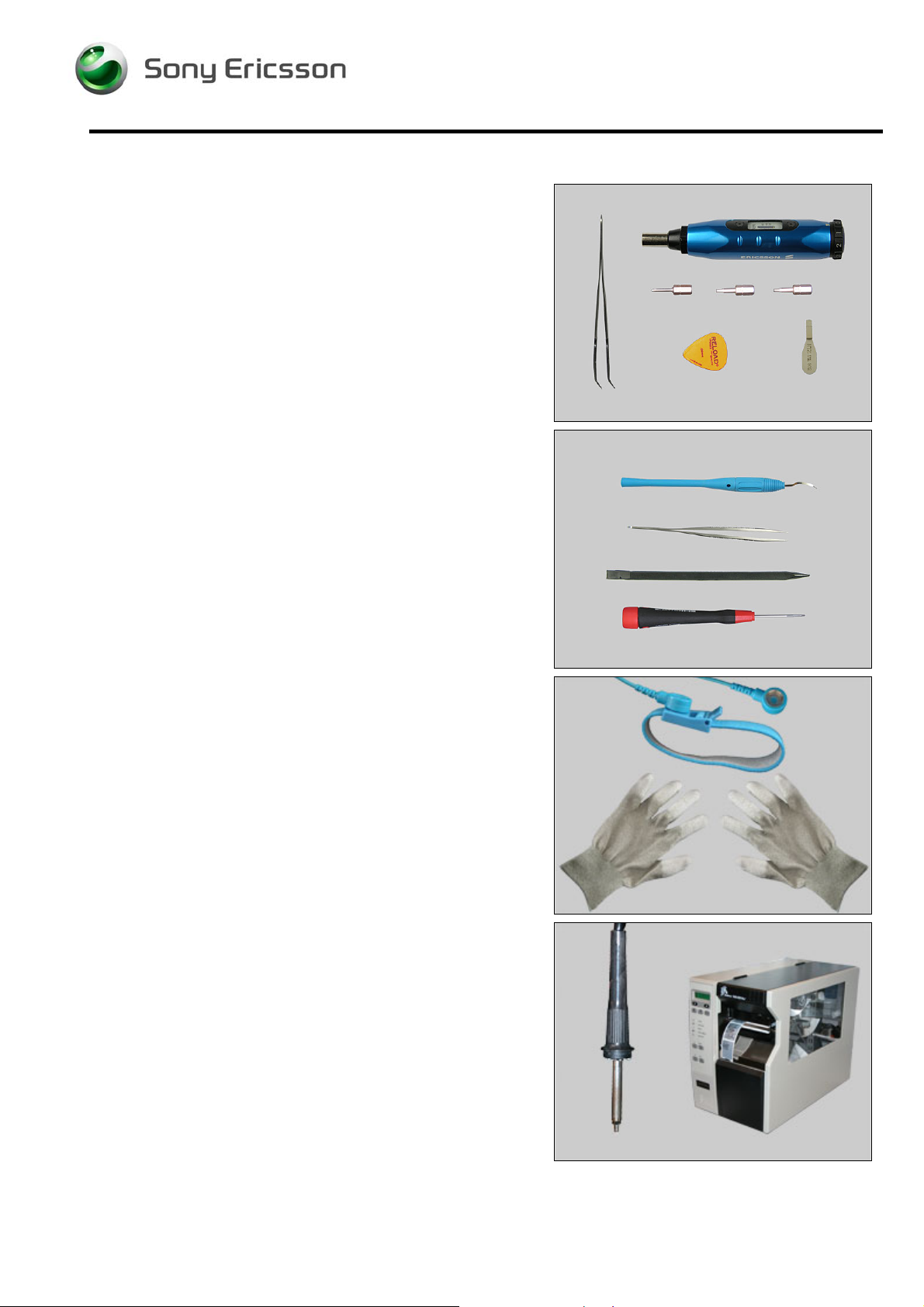
1.1 Equipment
SPECIAL TOOLS
Special tools text:
• NTZ122459 Torque Screwdriver (or equivalent)
• NTZ122288 Bit (T6)
• NTZ112478 Bit (T5)
• NTZ1121052 Bit(JCIS No 0)
• NTZ112302/2 Front opening tool
• NTZ112521 Flex film assembly tool
• NTZ112590 Plectrum/SVC & Repair
STANDARD TOOLS
Standard tools text:
• Dentist hook
• ESD tweezers
• Nylon Pointer
• Screwdriver
ESD EQUIPMENT
Protect the phone from ESD damages whenever it has
been opened by using:
• ESD-wristband
• ESD-gloves
LABEL EQUIPMENT
The following special equipment is required when replacing
or installing a new label:
• Hot air flow solder station
• Zebra printer connected to computer
1218-1731 Rev 3 5(87)
Company Internal
© Sony Ericsson Mobile Communi cat i ons AB
Page 6

Working Instruction, Mechanical
1.2 General cautions
The following cautions are considered to be generic for all phone models and will not be repeated in
the Disassembly, Replacements and Reassembly sections:
• S
WITCH OFF THE PHONE AND REMOVE ANY MEMORY STICK BEFORE THE START OF THE DISASSEMBLY!
• KEEP ALL CONTACT SURFACES CLEAN!
• BE CAREFUL WHEN USING TOOLS LIKE THE DENTIST HOOK, TWEEZERS, OPENING TOOLS, GUITAR PICK
ETC. TO AVOID SCRATCHES OR DAMAGES TO THE EXTERIOR AND INTERIOR PARTS OF THE PHONE!
E CAREFUL NOT TO DAMAGE ANY CONTACT SPRINGS!
• B
• REMEMBER TO REMOVE THE PROTECTION FOILS ON NEW PARTS SUCH AS THE FRONT COVER AND LCD!
• NEVER TOUCH THE DISPLAY GLASS!
SE AIR BLOW EQUIPMENT TO KEEP THE FRONT WINDOW AND DISPLAY MODULE DUST FREE!
• U
1.3 Adhesives
Use a dentist hook and/or the tweezers to remove old adhesives.
Clean the surface with isopropyl alcohol before attaching new adhesives.
1218-1731 Rev 3 6(87)
Company Internal
© Sony Ericsson Mobile Communi cat i ons AB
Page 7
Working Instruction, Mechanical
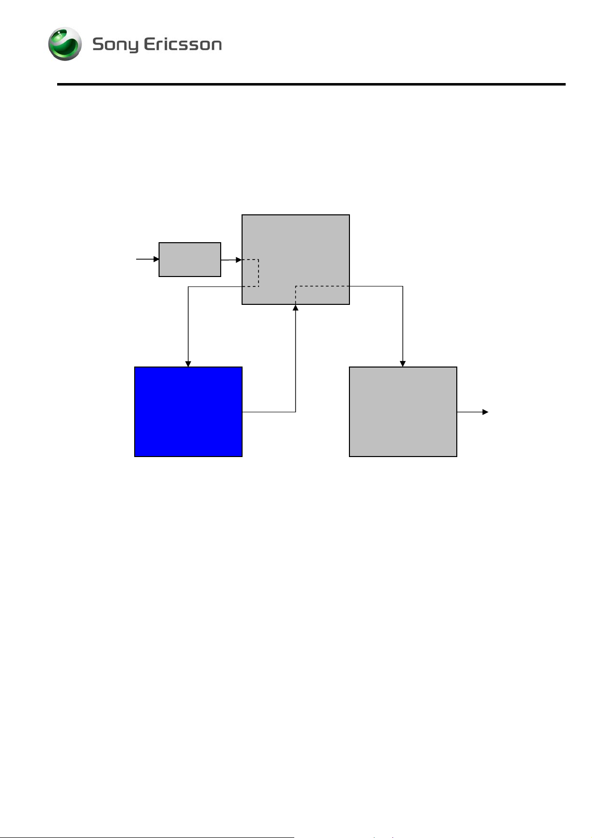
2 Disassembly
When you are going to replace a part being listed in Replacements, the instruction of that section
usually begins by directing you to this Disassembly section with a specification of the instructions you
have to carry out in order to disassemble the phone as far as needed before returning to
Replacements for the actual replacement.
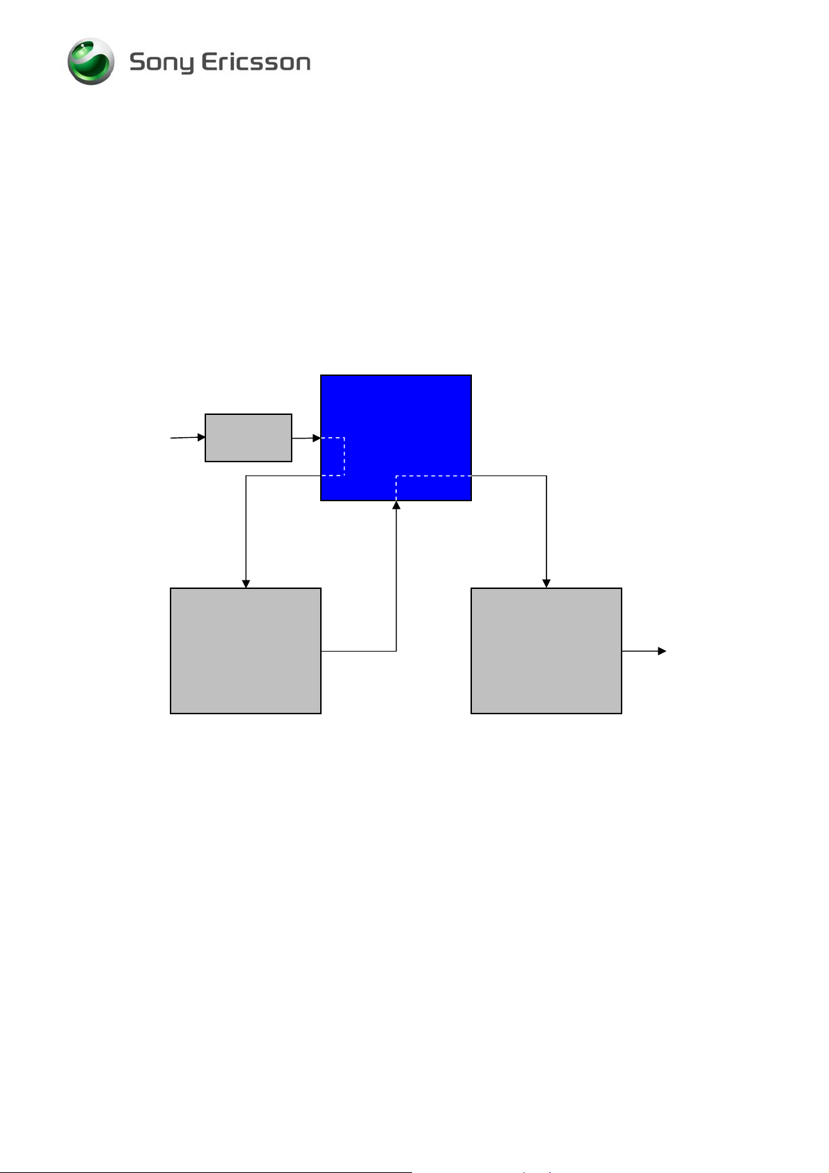
REPLACEMENTS
Start
Contents
page
DISASSEMBLY
REASSEMBLY
Done
1218-1731 Rev 3 7(87)
Company Internal
© Sony Ericsson Mobile Communi cat i ons AB
Page 8
Working Instruction, Mechanical
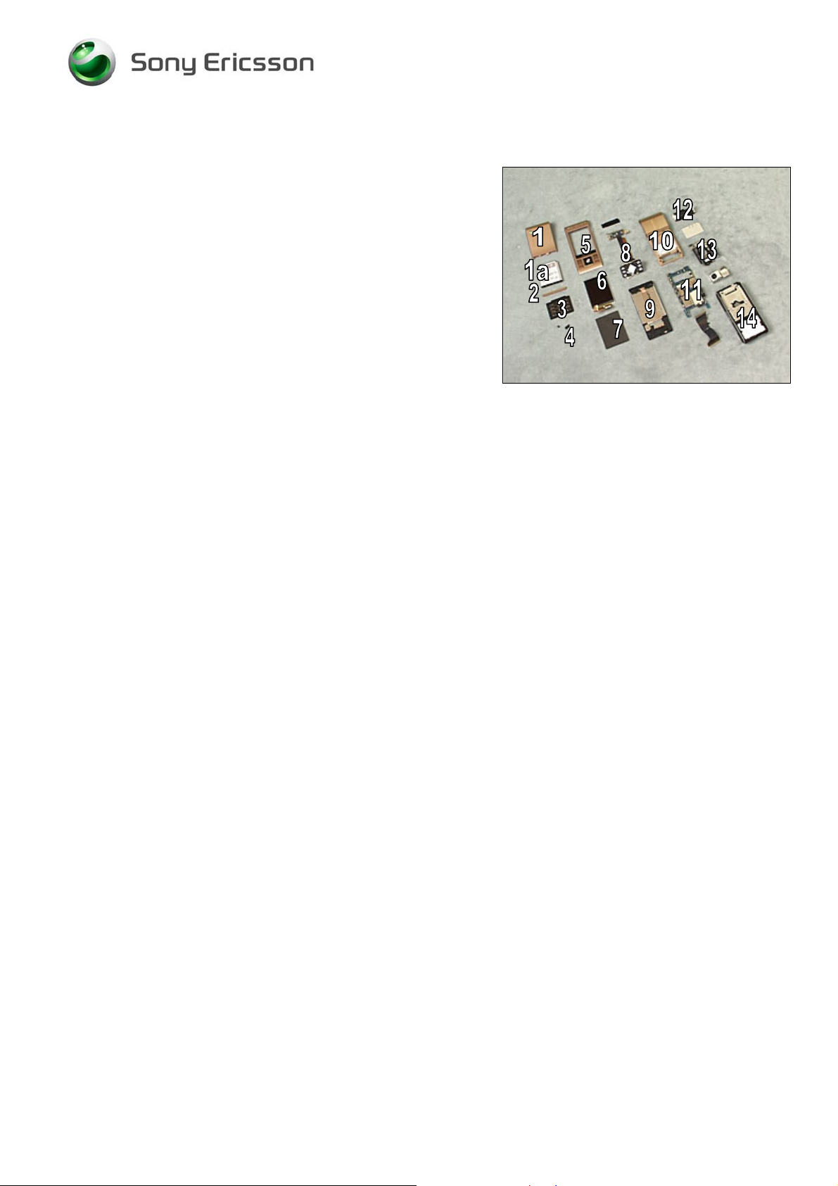
2.1 Overview
The disassembly is done in the following sequence:
1. Battery Cover
1a. Battery
2. Flip Inner
3. Keyboard
4. Cap Plastic RF Numeric Keyboard & Cap Numeric
Keyboard
5. Cover Flip Front
6. Display 2.41 TFT
7. LCD Support Sheet
8. PBA Key Flex Flip Complete
9. Cover Rear Assembly
10. Cover Base Rear Assembly
11. Main PBA
12. Loudspeaker Assembly
13. Flash Complete and Camera 8MP
14. Carrier Base Assembly
1218-1731 Rev 3 8(87)
Company Internal
© Sony Ericsson Mobile Communi cat i ons AB
Page 9
Working Instruction, Mechanical
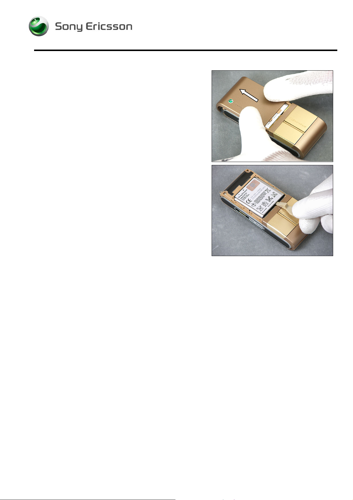
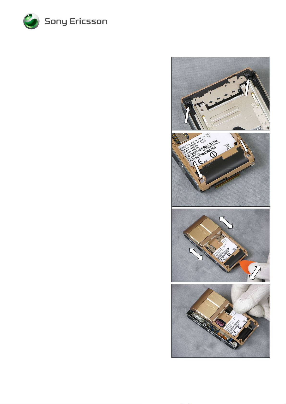
2.2 Battery Cover & Battery
Remove the Battery Cover.
Remove the Battery.
1218-1731 Rev 3 9(87)
Company Internal
© Sony Ericsson Mobile Communi cat i ons AB
Page 10
Working Instruction, Mechanical
2.3 Foil Flip Inner
Use a pair of ESD tweezers to remove the Flip Inner.
Use a Screwdriver with JCIS Bit to remove the two Screws
4.0x1.4.
2.4 Keyboard
Use a Screwdriver to loosen the keyboard from the opposite
side
Use a Flex Film Assembly Tool to remove the Keyboard
1218-1731 Rev 3 10(87)
Company Internal
© Sony Ericsson Mobile Communi cat i ons AB
Page 11
Working Instruction, Mechanical
2.5 Cap Plastic RF Numeric Keyboard & Cap Numeric Keyboard
Use a Screwdriver to remove the Cap Plastic RF Keyboard
Numeric on the opposite side.
Use Screwdriver to remove the Cap Numeric keyboard on
the opposite side.
1218-1731 Rev 3 11(87)
Company Internal
© Sony Ericsson Mobile Communi cat i ons AB
Page 12
Working Instruction, Mechanical
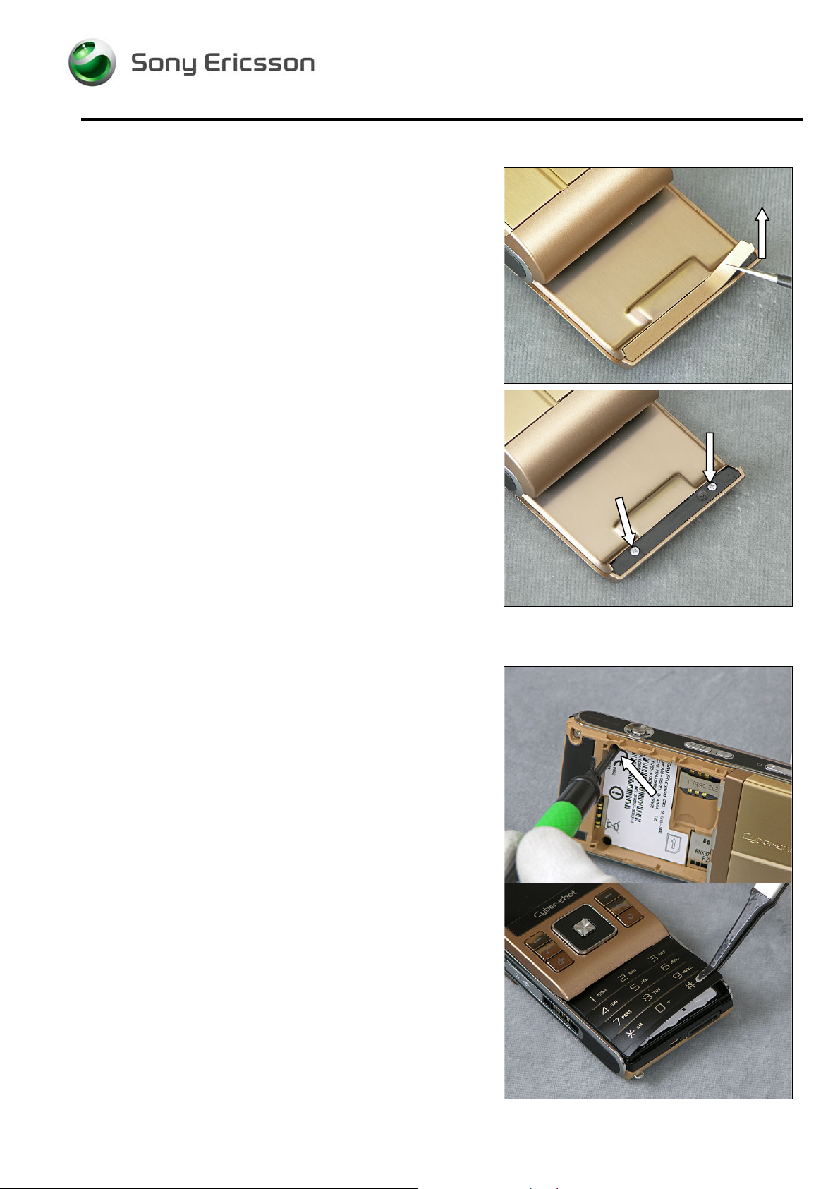
2.6 Cover Flip Front
Use your fingers to slide and position the Cover Flip Front
to make the two Screws 2.3x1.4 visible through the two
holes in the Cover Base Rear Assembly.
Use a Screwdriver with JCIS Bit to remove the two Screws
2.3x1.4.
Use a Guitar Pick to loosen the Cover Flip Front on both
sides.
Use your fingers to remove the Cover Flip Front.
1218-1731 Rev 3 12(87)
Company Internal
© Sony Ericsson Mobile Communi cat i ons AB
Page 13
Working Instruction, Mechanical
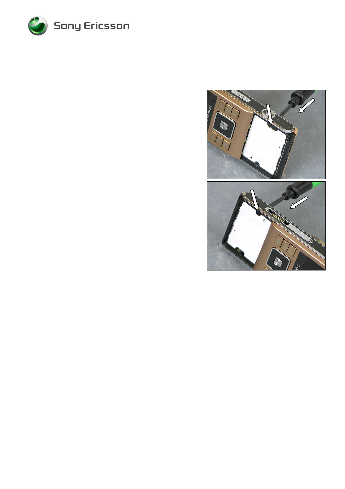
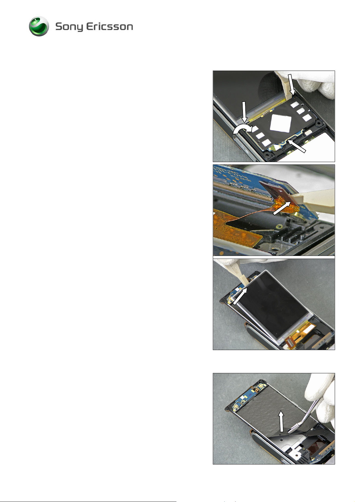
2.7 Display 2.41 TFT
Locate the three snap hooks and use a Front Opening Tool
to release the PCB-part of the PBA Key Flex Flip Complete.
Use a Front Opening Tool to disconnect the LCD FPC
Connector
BE VERY CAREFUL WHEN BENDING THE PCB-PART OF THE
KEY FLEX FLIP
E VERY CAREFUL NOT TO DAMAGE THE DISPLAY FLEX!
B
Use a Front Opening Tool to remove the Display 2.41 TFT.
2.8 LCD Support Sheet
Use a blunt pair of Tweezers to remove the LCD Support
Sheet.
1218-1731 Rev 3 13(87)
Company Internal
© Sony Ericsson Mobile Communi cat i ons AB
Page 14
Working Instruction, Mechanical
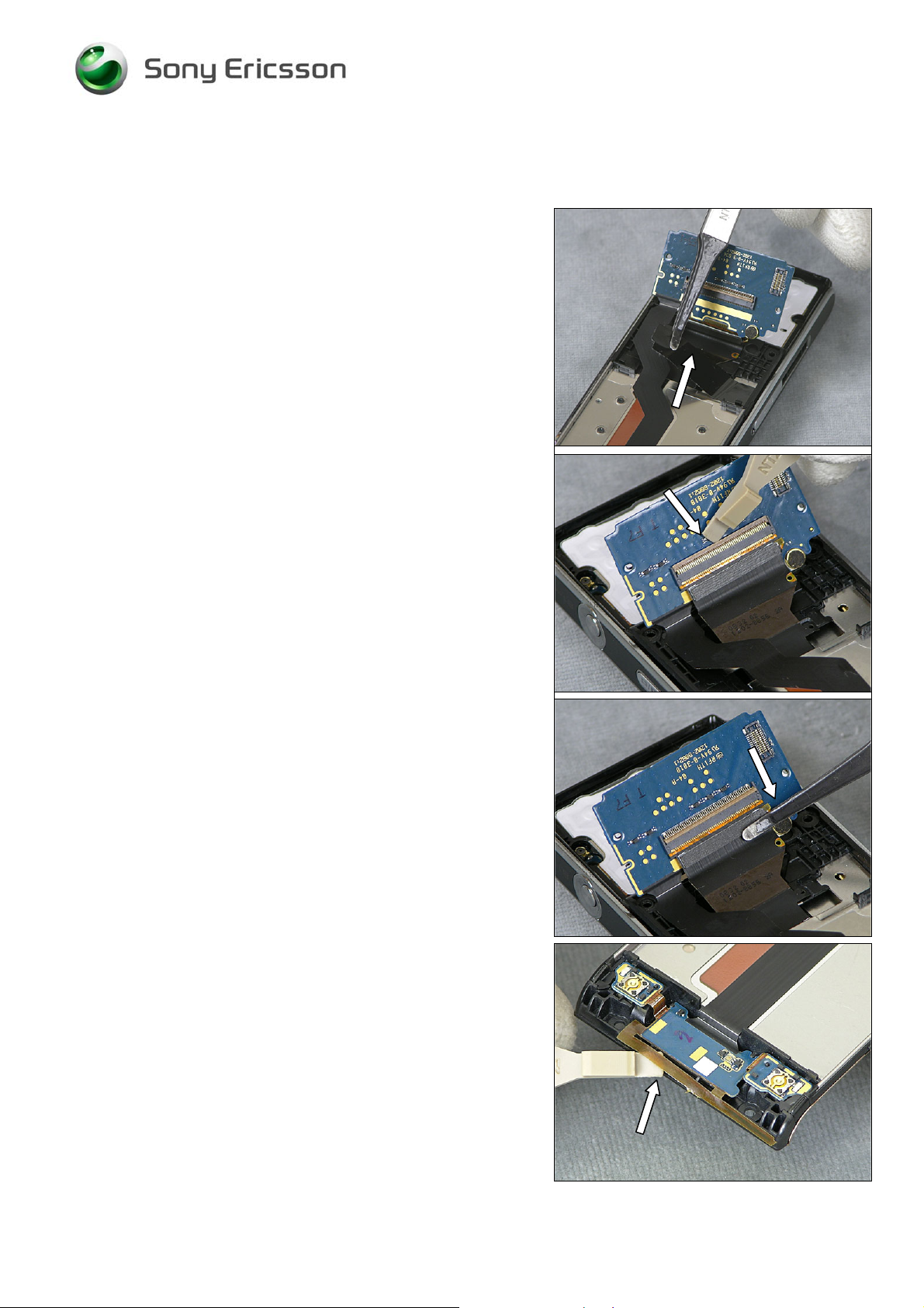
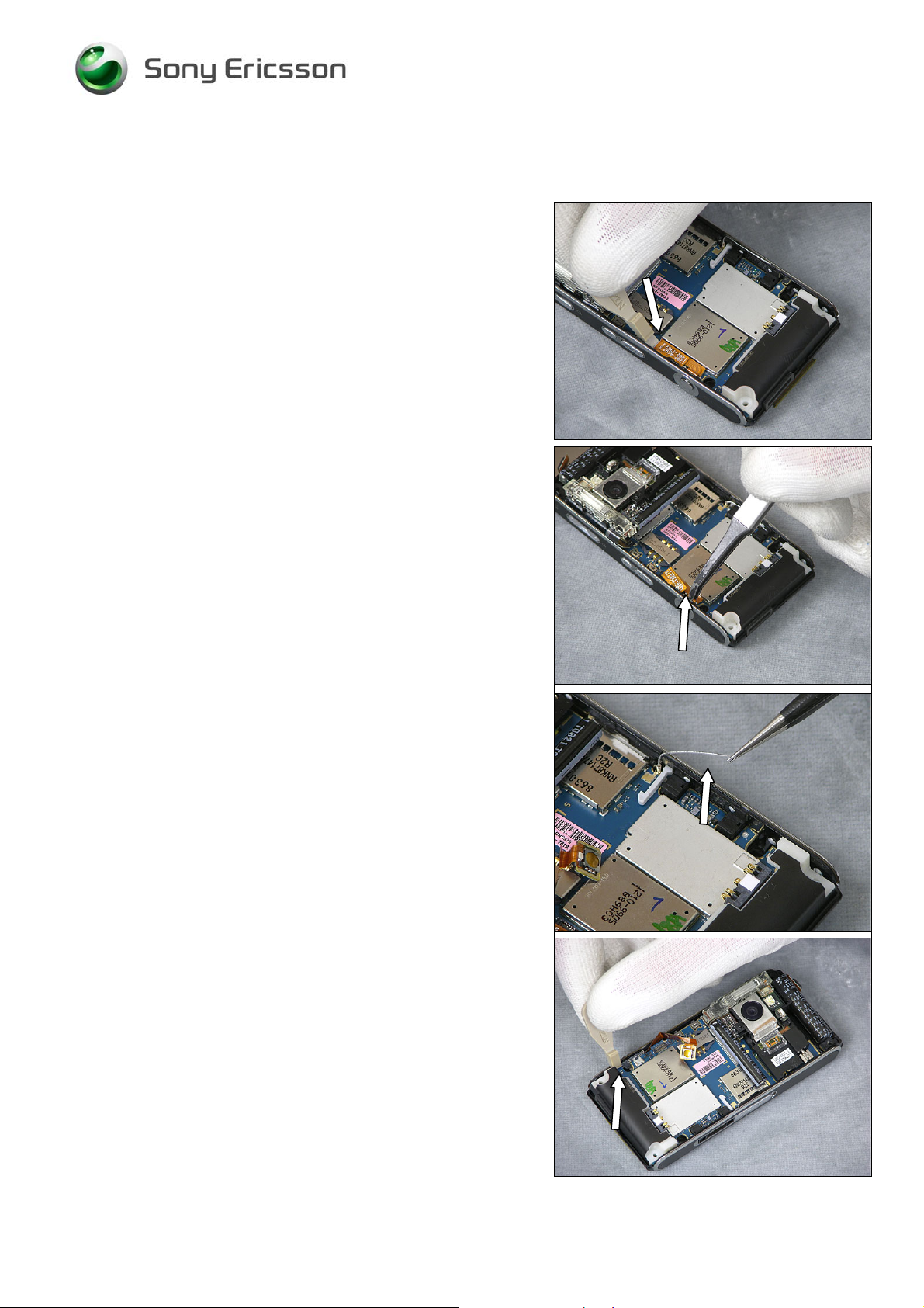
2.9 PBA Key Flex Flip Complete
Use a Flex Film Assembly Tool to remove the Foil Adhesive
Single Side 0.15 mm Flip Tape
Use a Front Opening Tool to unsnap the PBA Key Flex Flip
Complete connector
Use a Flex Film Assembly Tool to disconnect the Slider
FPC Assy from the PBA Key Flex Complete
Use a Front Opening Tool to loosen the GPS Antenna.
1218-1731 Rev 3 14(87)
Company Internal
© Sony Ericsson Mobile Communi cat i ons AB
Page 15
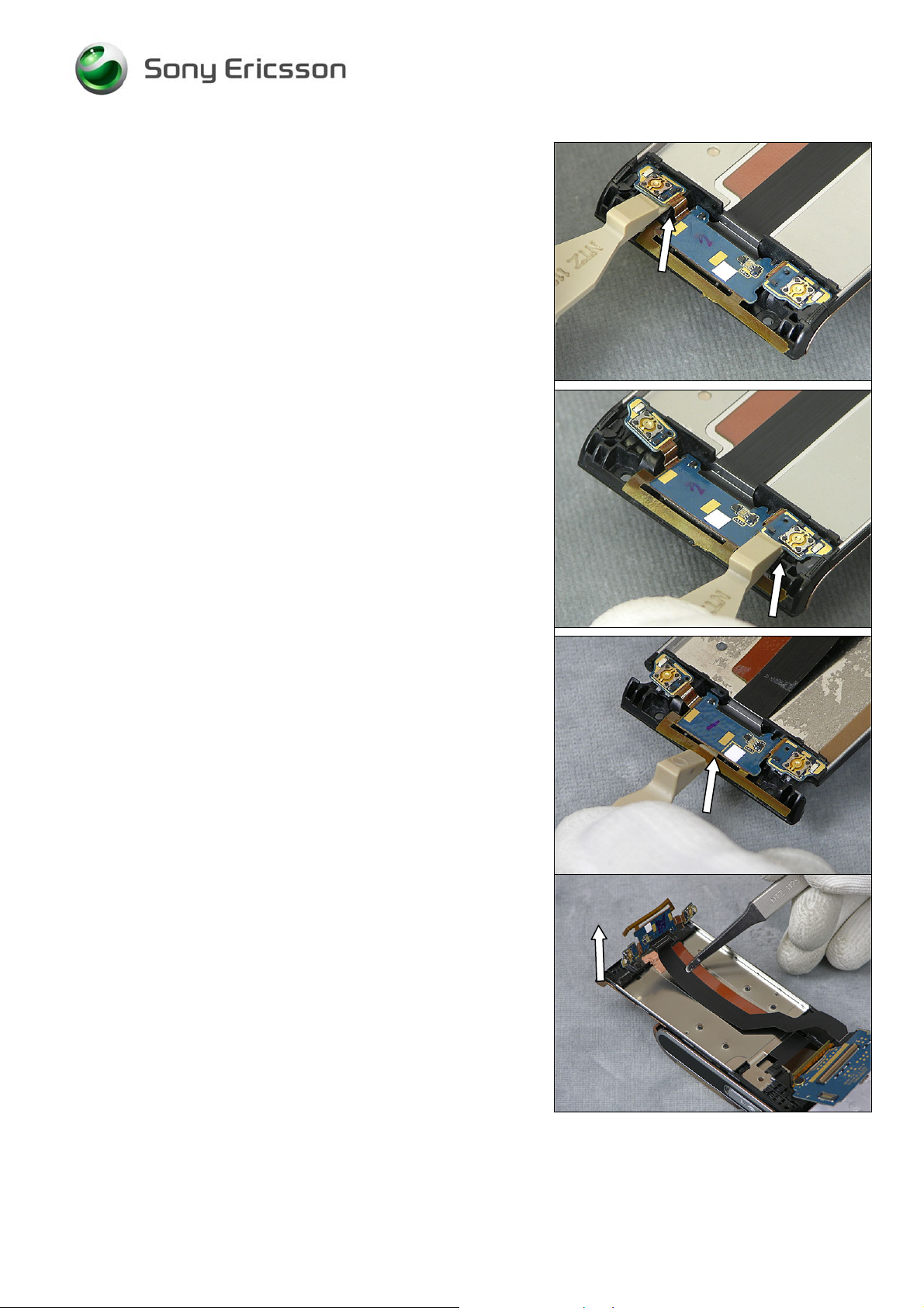
Working Instruction, Mechanical
Use a Front Opening Tool to loosen the Key B part of the
Board.
Use a Front Opening Tool to loosen the Key A part of the
Board.
Use a Front Opening Tool to loosen the GPS part of the
Board.
Use a Flex Film Assembly Tool to remove the PBA Key
Flex Flip Complete
1218-1731 Rev 3 15(87)
Company Internal
© Sony Ericsson Mobile Communi cat i ons AB
Page 16
Working Instruction, Mechanical
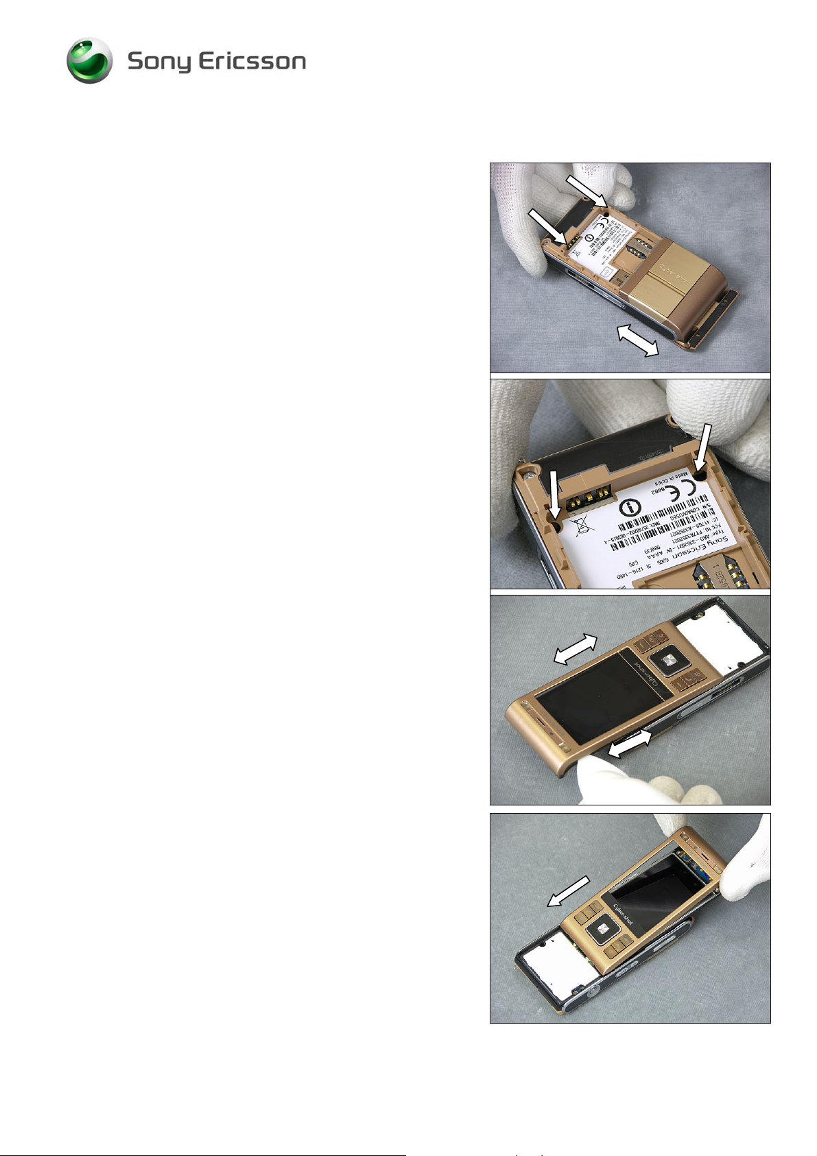
2.10 Cover Rear Assembly
Use a Flex Film Assembly Tool to loosen the Slider PPC
Assy from the Cover Rear Assembly
Use a Screwdriver with JCIS Bit to remove the four Flat
Head M1.4x1.7
Use a Flex Film Assembly Tool to loosen the Slider PPC
Assy from the back of the Cover Rear Assembly
Use your fingers to remove the Cover Rear Assembly
1218-1731 Rev 3 16(87)
Company Internal
© Sony Ericsson Mobile Communi cat i ons AB
Page 17
Working Instruction, Mechanical
2.11 Cover Base Rear Assembly
Use a Screwdriver with T5 Bit to remove the two Screws
Torx 5.0x1.6.
Use a Screwdriver with T6 Bit to remove the two Screws
Torx 5.3x1.6.
Use a Guitar Pick to loosen the Cover Base Rear Assembly
on three sides
Use your fingers to remove the Cover Base Rear Assembly.
1218-1731 Rev 3 17(87)
Company Internal
© Sony Ericsson Mobile Communi cat i ons AB
Page 18
Working Instruction, Mechanical
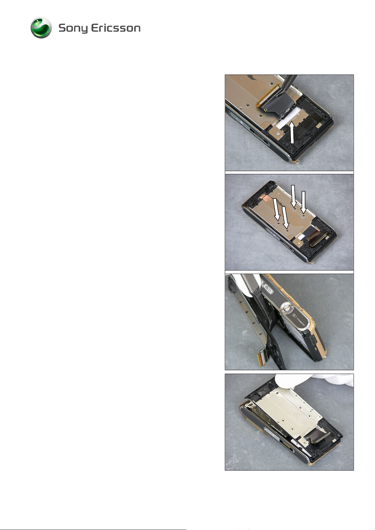
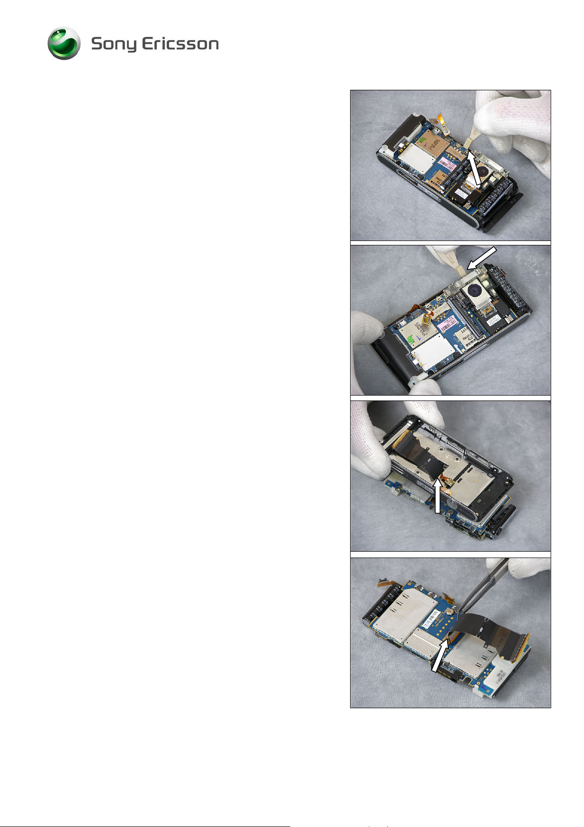
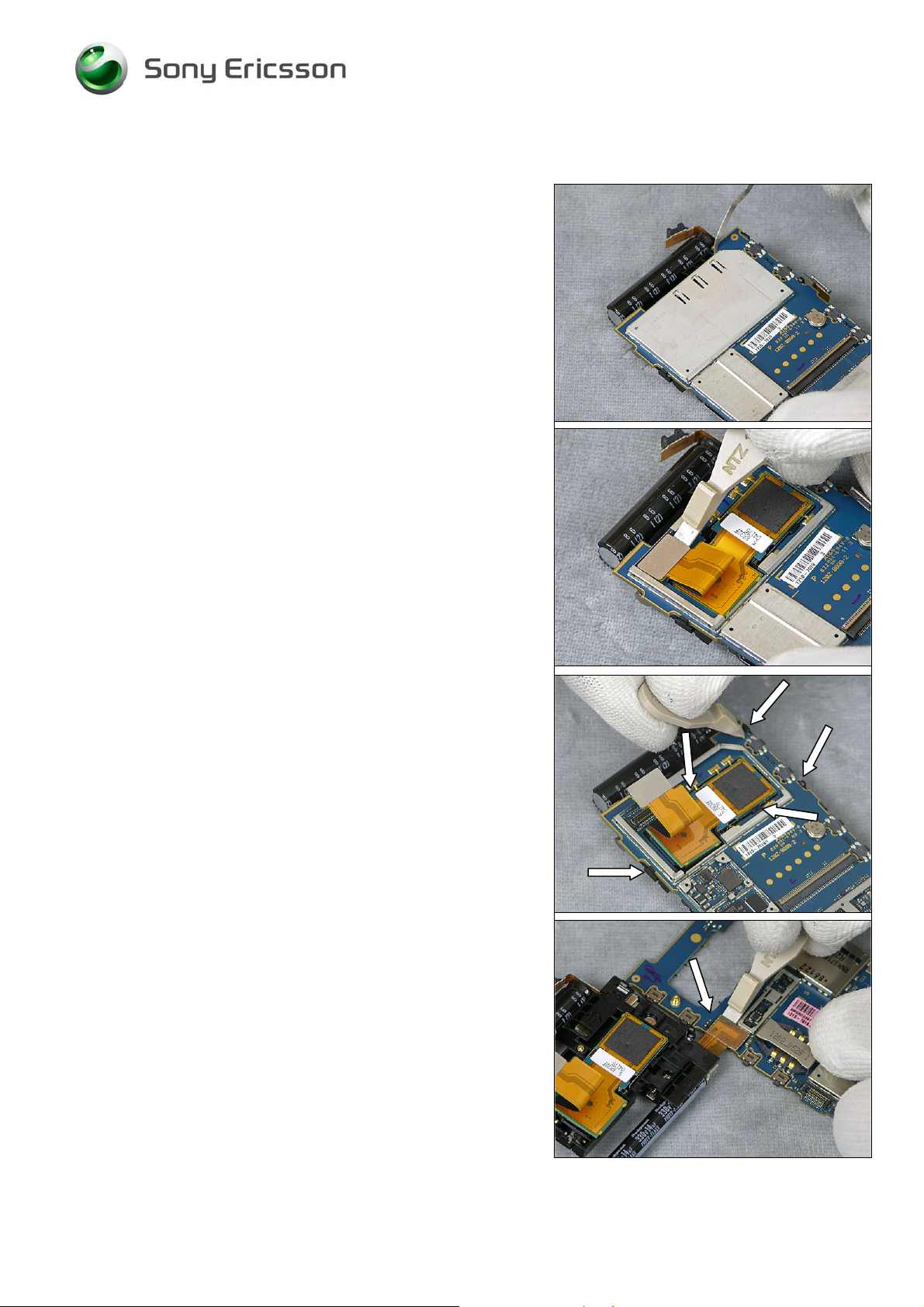
2.12 Main PBA
Use a Front Opening Tool to disconnect the Numeric Key
Foil Connector from the Main PBA
Use a Flex Film Assembly Tool to pull the Numeric Key Foil
out of the camera key switch supporter.
Use a Pair of ESD Tweezers to loosen the BT/WLAN
Antenna
BE VERY CAREFUL NOT TO DAMAGE THE MAIN PBA SWITCHES
WHEN LOOSENING THE
MAIN PBA!
Use a Front Opening Tool to bend the Carrier Base
Assembly away from the Main PBA and loosen the Main
PBA.
1218-1731 Rev 3 18(87)
Company Internal
© Sony Ericsson Mobile Communi cat i ons AB
Page 19
Working Instruction, Mechanical
Use a Front Opening Tool to bend the Carrier Base
Assembly away from the Main PBA and loosen the Main
PBA.
BE VERY CAREFUL NOT TO DAMAGE THE MAIN PBA SWITCHES
WHEN REMOVING THE
MAIN PBA!
Use a Front Opening Tool to bend the Carrier Base
Assembly away from the Main PBA and loosen the Main
PBA.
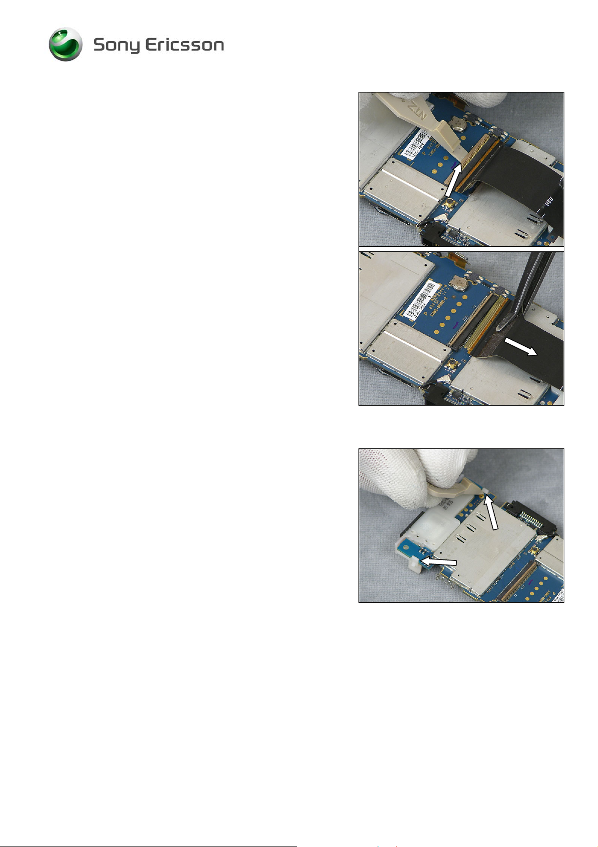
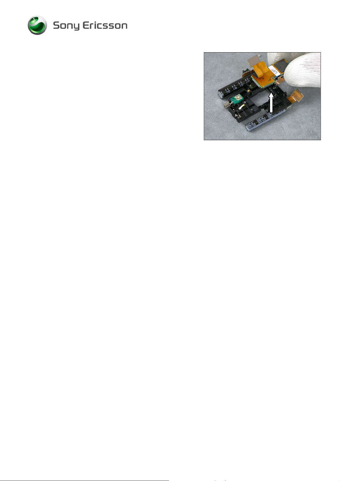
E VERY CAREFUL NOT TO DAMAGE THE SLIDER FPC ASSY!
B
Use your fingers to gently thread the Slider FPC Assy
through the gap
Use A Flex Film Assembly Tool to Loosen the Slider FPC
Assy Adhesive from the 100 pin FPC connector
B
E VERY CAREFUL NOT TO DAMAGE THE SLIDER FPC ASSY!
1218-1731 Rev 3 19(87)
Company Internal
© Sony Ericsson Mobile Communi cat i ons AB
Page 20
Working Instruction, Mechanical
Use a Front Opening Tool to unhook the board to flex
connector from the Main PBA.
Use a Flex Film Assembly Tool to remove the Slider FPC
Assy from the Main PBA
B
E VERY CAREFUL NOT TO DAMAGE THE SLIDER FPC ASSY!
2.13 Loudspeaker Assembly
Use a Front Opening Tool to release the snap hooks and
remove the Loudspeaker Assembly.
1218-1731 Rev 3 20(87)
Company Internal
© Sony Ericsson Mobile Communi cat i ons AB
Page 21
Working Instruction, Mechanical
2.14 Flash Complete and Camera 8MP
Use a Dentist Hook to remove the Shield Can Lid, Camera
Use a Front Opening Tool to disconnect the Camera
Connector from the Main PBA
Use a Front Opening Tool to release the five snap hooks
Turn over the Main PBA and use a Front Opening Tool to
disconnect the Flash Complete from the Main PBA
1218-1731 Rev 3 21(87)
Company Internal
© Sony Ericsson Mobile Communi cat i ons AB
Page 22
Working Instruction, Mechanical
Use your fingers to gently remove the Camera 8MP from
the Flash Complete
1218-1731 Rev 3 22(87)
Company Internal
© Sony Ericsson Mobile Communi cat i ons AB
Page 23
Working Instruction, Mechanical
3 Replacements
Search for the part to be replaced on the Contents page and go to that instruction to be found in this
Replacements section.
The instruction usually begins by directing you to the Disassembly section with a specification of the
instructions you have to carry out in order to disassemble the phone as far as needed before the
actual replacement.
Go back to this Replacements section and carry out the instruction.
The instruction usually ends by directing you to the Reassembly section with a specification of the
instructions you have to carry out in order to reassemble the phone.
REPLACEMENTS
Start
Contents
page
DISASSEMBLY REASSEMBLY
Done
1218-1731 Rev 3 23(87)
Company Internal
© Sony Ericsson Mobile Communi cat i ons AB
Page 24

Working Instruction, Mechanical
3.1 Battery Cover & Battery
Follow the 2.2 Disassembly instructions!
Replace Battery Cover and/or Battery
Follow the 4.14 Reassembly instructions!
3.2 Cover Flip Front Assembly
Follow the 2.2 – 2.6 Disassembly instructions!
Replace Cover Flip Front Assembly
Follow the 4.10 – 4.14 Reassembly instructions!
3.3 Cover Base Rear Assembly
Follow the 2.2 – 2.11 Disassembly instructions!
Replace Cover Base Rear Assembly
Follow the 4.5 – 4.14 Reassembly instructions!
3.4 Flash Complete
Follow the 2.2 – 2.14 Disassembly instructions!
Replace Flash Complete
Follow the 4.2 – 4.14 Reassembly instructions!
3.5 PBA Key Flex Flip Complete
Follow the 2.2 – 2.9 Disassembly instructions!
Replace Key Flex Flip Complete
Follow the 4.7 – 4.14 Reassembly instructions!!
3.6 Slider FPC Assy
Follow the 2.2 – 2.12 Disassembly instructions!
Replace Slider FPC Assy
Follow the 4.4 – 4.14 Reassembly instructions!
3.7 Cover Rear Assembly
Follow the 2.2 – 2.10 Disassembly instructions!
Replace Cover Rear Assembly
Follow the 4.6 – 4.14 Reassembly instructions!
1218-1731 Rev 3 24(87)
Company Internal
© Sony Ericsson Mobile Communi cat i ons AB
Page 25

Working Instruction, Mechanical
3.8 Carrier Base Assembly
Follow the 2.2 – 2.12 Disassembly instructions! And 3.29-3.31, 3.34 – 3.36, 3.62 Replacement
Instructions!
Replace Carrier Base Assembly
Follow the 4.4 – 4.14 Reassembly instructions! And 3.29-3.31, 3.34 – 3.36, 3.62 Replacement
Instructions!
3.9 Camera 8 MP
Follow the 2.2 – 2.14 Disassembly instructions!
Replace Camera 8 MP
Follow the 4.2 – 4.14 Reassembly instructions!
3.10 Foil Flip Inner
Follow the 2.2 – 2.3 Disassembly instructions!
Replace Foil Flip Inner
Follow the 4.13 – 4.14 Reassembly instructions!
3.11 LCD Support Sheet
Follow the 2.2 – 2.8 Disassembly instructions!
Replace LCD Support Sheet
Follow the 4.8 – 4.14 Reassembly instructions!
3.12 Loudspeaker Assembly
Follow the 2.2 – 2.13 Disassembly instructions!
Replace Loudspeaker Assembly
Follow the 4.3 – 4.14 Reassembly instructions!
3.13 Screw 4.0x1.4
Follow the 2.2 – 2.3 Disassembly instructions!
Replace Screw 4.0x1.4 (torque 11Ncm)
Follow the 4.13 – 4.14 Reassembly instructions!
3.14 Screw 2.3x1.4
Follow the 2.2 – 2.6 Disassembly instructions!
Replace Screw 2.3x1.4 (torque 11Ncm)
Follow the 4.10 – 4.14 Reassembly instructions!
1218-1731 Rev 3 25(87)
Company Internal
© Sony Ericsson Mobile Communi cat i ons AB
Page 26

Working Instruction, Mechanical
3.15 Screw Torx 5.3x1.6
Follow the 2.2 – 2.11 Disassembly instructions!
Replace Screw Torx 5.3x1.6 (torque 11Ncm)
Follow the 4.5 - 4.14 Reassembly instructions!
3.16 Screw T o rx 5.0x1.6
Follow the 2.2 – 2.11 Disassembly instructions!
Replace Screw Torx 5.0x1.6 (torque 11Ncm)
Follow the 4.5 – 4.14 Reassembly instructions!
3.17 Screw Philips M1.4x1.7
Follow the 2.2 – 2.12 Disassembly instructions! And 3.62 Replacement Instructions!
Replace Flat Head M1.4x1.7 (torque 11Ncm)
Follow the 4.4 – 4.14 Reassembly instructions! And 3.62 Replacement Instructions!
3.18 Cap Plastic RF Keyboard Numeric
Follow the 2.2 – 2.5 Disassembly instructions!
Replace Cap Plastic RF Numeric Keyboard
Follow the 4.11 – 4.14 Reassembly instructions!
3.19 Cap Numeric Keyboard
Follow the 2.2 – 2.5 Disassembly instructions!
Replace Cap Numeric Keyboard
Follow the 4.11 – 4.14 Reassembly instructions!
3.20 Foil Adhesive Single Side 0.15 mm Flip Tape
Follow the 2.2 – 2.9 Disassembly instructions!
Replace Foil Adhesive Single Side 0.15 mm Flip Tape
Follow the 4.7 – 4.14 Reassembly instructions!
1218-1731 Rev 3 26(87)
Company Internal
© Sony Ericsson Mobile Communi cat i ons AB
Page 27
Working Instruction, Mechanical
3.21 Display 2.41 TFT
Follow the 2.2 – 2.7 Disassembly instructions!
Fold the Display Flex between the cutouts.
Replace Display 2.41 TFT
Follow the 4.9 – 4.14 Reassembly instructions!
3.22 Cover Flip Inner Metal
Removal
Follow the 2.3 Disassembly instructions!
Use a Guitar Pick to loosen the Cover Flip Inner Metal. Use
your fingers to remove the Cover Flip Inner Metal.
Installation
Use your fingers to place the Cover Flip Inner Metal.
Use your fingers to attach the Cover Flip Inner Metal. Press
with your fingers on the entire surface
Follow the 4.13 Reassembly instructions!
1218-1731 Rev 3 27(87)
Company Internal
© Sony Ericsson Mobile Communi cat i ons AB
Page 28

Working Instruction, Mechanical
3.23 Cap Reinforcement Plug (Right and Left)
Removal (Right)
Follow the 22 – 2.9 Disassembly instructions!
Use a dentist hook to remove the Cap Reinforcement Plug
Right.
Installation
Use a pair of ESD Tweezers to attach the Cap
Reinforcement Plug (Right)
Follow the 4.7 – 4.14 Reassembly instructions!
Removal (Left)
Follow the 2.2 – 2.9 Disassembly instructions!
Use a dentist hook to remove the Cap Reinforcement Plug
Left.
Installation
Use a pair of ESD Tweezers to attach the Cap
Reinforcement Plug (Right)
Follow the 4.7 – 4.14 Reassembly instructions!
1218-1731 Rev 3 28(87)
Company Internal
© Sony Ericsson Mobile Communi cat i ons AB
Page 29

Working Instruction, Mechanical
3.24 Numeric Key Foil
Removal
Follow the 2.2 – 2.12 Disassembly instructions!
Use a blunt pair of Tweezers to remove the Light GU
Numeric.
Use a Flex Film Assembly Tool to remove the Numeric Key
Foil.
Installation
Use your fingers to position the Numeric Key Foil.
MAKE SURE THE ALIGNMENT IS CORRECT!
1218-1731 Rev 3 29(87)
Company Internal
© Sony Ericsson Mobile Communi cat i ons AB
Page 30

Working Instruction, Mechanical
Use your fingers to attach the Numeric Key Foil
Use a pair of ESD Tweezers to position the Light GU
Numeric
M
AKE SURE THE ALIGNMENT IS CORRECT!
Use your fingers to attach the Light Gu Numeric
Follow the 4.4 – 4.14 Reassembly instructions!
1218-1731 Rev 3 30(87)
Company Internal
© Sony Ericsson Mobile Communi cat i ons AB
Page 31

Working Instruction, Mechanical
3.25 Keyboard Navigation
Removal
Follow the 2.2 – 2.6 Disassembly instructions!
Use a pair of ESD Tweezers to loosen the Keyboard
Navigation from the Cover Flip Front.
Use a pair of ESD Tweezers to remove the Keyboard
Navigation from the Cover Flip Front.
Installation
Use your fingers to position the center of the Keyboard
Navigation on the Cover Flip Front.
BE CAREFUL NOT TO TOUCH THE ADHESIVE!
Use your fingers to attach the Keyboard Navigation.
Follow the 4.10 – 4.14 Reassembly instructions!
1218-1731 Rev 3 31(87)
Company Internal
© Sony Ericsson Mobile Communi cat i ons AB
Page 32

Working Instruction, Mechanical
3.26 Key A/B Left
Removal
Follow the 2.2 – 2.6 Disassembly instructions!
Use a pair of ESD Tweezers to remove the Key A/B Left
from the Cover Flip Front.
Installation
Use your fingers to attach the Key A/B Left on the Cover
Flip Front.
Follow the 4.10 – 4.14 Reassembly instructions!
1218-1731 Rev 3 32(87)
Company Internal
© Sony Ericsson Mobile Communi cat i ons AB
Page 33

Working Instruction, Mechanical
3.27 Key A/B Right
Removal
Follow the 2.2 – 2.6 Disassembly instructions!
Use a pair of ESD Tweezers to remove the Key A/B Right
from the Cover Flip Front.
Installation
Use your fingers to attach the Key A/B Right on the Cover
Flip Front.
Follow the 4.10 – 4.14 Reassembly instructions!
1218-1731 Rev 3 33(87)
Company Internal
© Sony Ericsson Mobile Communi cat i ons AB
Page 34

Working Instruction, Mechanical
3.28 Co Brand Label
Removal
BE CAREFUL NOT TO DAMAGE THE COVER FLIP FRONT!
No disassembly needed!
Use a Dentist Hook to loosen the Co Brand Label.
Use a pair of ESD Tweezers to remove the Co Brand Label.
Installation
Use a pair of ESD Tweezers to place the Co Brand Label.
Use your fingers to attach the Co Brand Label.
No reassembly needed!
1218-1731 Rev 3 34(87)
Company Internal
© Sony Ericsson Mobile Communi cat i ons AB
Page 35

Working Instruction, Mechanical
3.29 Key V olume
Removal
Follow the 2.2 – 2.12 Disassembly instructions!
Use a pair of ESD Tweezers to remove the Key Volume.
Installation
Use a pair of ESD Tweezers to position the Key Volume.
Follow the 4.4 – 4.14 Reassembly instructions!
3.30 Key Mode
Removal
Follow the 2.2 – 2.12 Disassembly instructions!
Use a pair of ESD Tweezers to remove the Key Mode.
Installation
Use a pair of ESD Tweezers to position the Key Mode.
Follow the 4.4 – 4.14 Reassembly instructions!
1218-1731 Rev 3 35(87)
Company Internal
© Sony Ericsson Mobile Communi cat i ons AB
Page 36

Working Instruction, Mechanical
3.31 Key Camera
Removal
Follow the 2.2 – 2.12 Disassembly instructions!
Use a pair of ESD Tweezers to remove the Key Camera.
Installation
Use a pair of ESD Tweezers to position the Key Camera.
Follow the 4.4 – 4.14 Reassembly instructions!
1218-1731 Rev 3 36(87)
Company Internal
© Sony Ericsson Mobile Communi cat i ons AB
Page 37

Working Instruction, Mechanical
3.32 M2 Lid
Removal
Follow the 2.2 – 2.11 Disassembly instructions!
Open the M2 Lid.
Use a pair of ESD Tweezers to remove the M2 Lid.
Installation
Use your fingers to position the M2 Lid.
Follow the 4.5 – 4.14 Reassembly instructions!
1218-1731 Rev 3 37(87)
Company Internal
© Sony Ericsson Mobile Communi cat i ons AB
Page 38

Working Instruction, Mechanical
3.33 Microphone Gasket
Removal
Follow the 2.2 – 2.6 Disassembly instructions!
Use a pair of ESD Tweezers to remove the Microphone
Gasket.
Installation
Use a pair of ESD Tweezers to position the Microphone
Gasket.
Follow the 4.10 – 4.14 Reassembly instructions!
1218-1731 Rev 3 38(87)
Company Internal
© Sony Ericsson Mobile Communi cat i ons AB
Page 39

Working Instruction, Mechanical
3.34 BT/WLAN Antenna
Removal
Follow the 2.2 – 2.12 Disassembly instructions!
Use a Front Opening Tool to loosen the BT/WLAN Antenna.
Use a Front Opening Tool to disconnect the BT/WLAN
Antenna.
Installation
Use your fingers to connect the BT/WLAN Antenna.
M
AKE SURE THE BT/WLAN ANTENNA IS COMPLETELY
CONNECTED
!
Use a Front Opening Tool to attach the BT/WLAN Antenna
M
AKE SURE THE BT/WLAN ANTENNA IS COMPLETELY HELD
BY THE CLIP
Follow the 4.4– 4.14 Reassembly instructions!
!
1218-1731 Rev 3 39(87)
Company Internal
© Sony Ericsson Mobile Communi cat i ons AB
Page 40

Working Instruction, Mechanical
3.35 Left Sidepanel
Removal
No Disassembly needed!
Use a Dentist Hook to remove the Left Sidepanel.
Installation
Use a Flex Film Assembly Tool to position the Left
Sidepanel.
Use your fingers to attach the Left Sidepanel
No Reassembly needed!
1218-1731 Rev 3 40(87)
Company Internal
© Sony Ericsson Mobile Communi cat i ons AB
Page 41

Working Instruction, Mechanical
3.36 Right Sidep anel Bottom
Removal
No Disassembly needed!
Use a Dentist Hook to remove the Right Sidepanel Bottom.
Installation
Use a Flex Film Assembly Tool to position the Right
Sidepanel Bottom.
Use your fingers to attach the Right Sidepanel Bottom
No Reassembly needed!
1218-1731 Rev 3 41(87)
Company Internal
© Sony Ericsson Mobile Communi cat i ons AB
Page 42

Working Instruction, Mechanical
3.37 Right Sidepanel T op
Removal
No Disassembly needed!
Use a Dentist Hook to loosen the Right Sidepanel Top
Use a Flex Film Assembly Tool to remove the Right
Sidepanel Top
Installation
Use a Flex Film Assembly Tool to position the Right
Sidepanel Top
Use your fingers to attach the Right Sidepanel Top
No Reassembly needed!
1218-1731 Rev 3 42(87)
Company Internal
© Sony Ericsson Mobile Communi cat i ons AB
Page 43

Working Instruction, Mechanical
3.38 Ear Speaker
Removal
Follow the 2.2 – 2.6 Disassembly instructions!
Use a Dentist Hook to loosen the Ear Speaker.
Use a pair of ESD Tweezers to remove the Ear Speaker.
Installation
Use a pair of ESD Tweezers to place the Ear Speaker.
MAKE SURE TO ALIGN THE SPEAKER PROPERLY! SEE ARROW!
MAKE SURE TO ALIGN THE SPEAKER PROPERLY!
D
O NOT TOUCH THE SPRINGS ON THE EAR SPEAKER!
Follow the 4.10 – 4.14 Reassembly instructions!
1218-1731 Rev 3 43(87)
Company Internal
© Sony Ericsson Mobile Communi cat i ons AB
Page 44

Working Instruction, Mechanical
3.39 Vibrator
Removal
Follow the 2.2 – 2.14 Disassembly instructions!
Use a Front Opening Tool to remove Vibrator.
Installation
Use a pair of ESD Tweezers to position the Vibrator.
Use a Front Opening Tool to attach the Vibrator.
O NOT TOUCH THE SPRINGS ON THE VIBRATOR!
D
Follow the 4.2 – 4.14 Reassembly instructions!
1218-1731 Rev 3 44(87)
Company Internal
© Sony Ericsson Mobile Communi cat i ons AB
Page 45

Working Instruction, Mechanical
3.40 Light GU Navigation
Removal
Follow the 2.2 – 2.6 Disassembly instructions!
Use a Flex Film Assembly Tool to remove the Light GU
Navigation
Installation
Use a Flex Film Assembly Tool to position the Light GU
Navigation
MAKE SURE THE ALIGNMENT IS CORRECT!
Use your fingers to attach the Light Gu Navigation
O NOT ATTACH THE LIGHT GU NAVIGATION BY PRESSING ON
D
THE BUTTONS
!
Follow the 4.10 – 4.14 Reassembly instructions!
1218-1731 Rev 3 45(87)
Company Internal
© Sony Ericsson Mobile Communi cat i ons AB
Page 46

Working Instruction, Mechanical
3.41 Dome Foil Flip
Removal
Follow the 2.2 – 2.6 Disassembly instructions!
Use a Flex Film Assembly Tool to remove the Light GU
Navigation
Use a Flex Film Assembly Tool to remove the Dome Foil
Flip
Installation
Use a Flex Film Assembly Tool to position the Dome Foil
Flip
MAKE SURE THE ALIGNMENT IS CORRECT!
1218-1731 Rev 3 46(87)
Company Internal
© Sony Ericsson Mobile Communi cat i ons AB
Page 47

Working Instruction, Mechanical
Use your fingers to attach the Dome Foil Flip
O NOT ATTACH THE LIGHT GU NAVIGATION BY PRESSING ON
D
THE BUTTONS
!
Use a Flex Film Assembly Tool to position the Light GU
Navigation
MAKE SURE THE ALIGNMENT IS CORRECT!
Use your fingers to attach the Light Gu Navigation
O NOT ATTACH THE LIGHT GU NAVIGATION BY PRESSING ON
D
THE BUTTONS!
Follow the 4.10 – 4.14 Reassembly instructions!
1218-1731 Rev 3 47(87)
Company Internal
© Sony Ericsson Mobile Communi cat i ons AB
Page 48

Working Instruction, Mechanical
3.42 PBA Key Flex Flip Complete
Removal
Follow the 2.2 – 2.9 Disassembly instructions!
Installation
Follow the 4.7 – 4.14 Reassembly instructions!
1218-1731 Rev 3 48(87)
Company Internal
© Sony Ericsson Mobile Communi cat i ons AB
Page 49

Working Instruction, Mechanical
3.43 Shield Can Lid Flip
Removal
Follow the 2.2 – 2.9 Disassembly instructions!
Use a Dentist Hook to loosen the Shield Can Lid Flip
Use a Flex Film Assembly Tool to remove the Shield Can
Lid Flip
Installation
Use a Flex Film Assembly Tool to position the Shield Can
Lid Flip
Use your fingers to attach the Shield Can Lid Flip
Follow the 4.7 – 4.14 Reassembly instructions!
1218-1731 Rev 3 49(87)
Company Internal
© Sony Ericsson Mobile Communi cat i ons AB
Page 50

Working Instruction, Mechanical
3.44 Cushion 1,0mm1,3x5,1,0 Conductive
Removal
Follow the 2.2 – 2.6 Disassembly instructions!
Use a Pair of ESD Tweezers to remove the Cushion
1,0mm1,3x5,1,0 Conductive
Installation
Use a Pair of ESD Tweezers to attach the Cushion
1,0mm1,3x5,1,0 Conductive
M
AKE SURE THE ALIGNMENT IS CORRECT!
Follow the 4.10 – 4.14 Reassembly instructions!
1218-1731 Rev 3 50(87)
Company Internal
© Sony Ericsson Mobile Communi cat i ons AB
Page 51

Working Instruction, Mechanical
3.45 Foil Adhesive 0.048 mm Flex Flip
Removal
Follow the 2.2 – 2.9 Disassembly instructions!
Use a Guitar Pick to peel off the Foil Adhesive 0.048 mm
Flex Flip
Use a Guitar Pick to peel off the Foil Adhesive 0.048 mm
Flex Flip from the PBA Key Flex Flip Complete
Installation
Use a Flex Film Assembly Tool to position the Foil Adhesive
0.048 mm Flex Flip on the PBA Key Flex Flip Complete
Use a Flex Film Assembly Tool to remove the protection
tape from the Foil Adhesive 0.048 mm Flex Flip
Follow the 4.7 – 4.14 Reassembly instructions!
1218-1731 Rev 3 51(87)
Company Internal
© Sony Ericsson Mobile Communi cat i ons AB
Page 52

Working Instruction, Mechanical
3.46 Foil Adhesive Conductive 0.05 mm protection tape, front
Removal
Follow the 2.2 – 2.6 Disassembly instructions!
Use a pair of ESD Tweezers to remove the Foil Adhesive
Conductive 0.05 mm protection tape, front
Installation
Use a Flex Film Assembly Tool to position the Foil Adhesive
Conductive 0.05 mm protection tape, front
Use a Flex Film Assembly Tool to remove the protection
tape from the Foil Adhesive Conductive 0.05 mm protection
tape, front
M
AKE SURE THE FOIL ADHESIVE CONDUCTIVE 0.05 MM GPS
ESD PROTECTION TAPE, FRONT COMPLETELY COVER THE
COVER FLIP FRONT!
Follow the 4.10 – 4.14 Reassembly instructions!
1218-1731 Rev 3 52(87)
Company Internal
© Sony Ericsson Mobile Communi cat i ons AB
Page 53

Working Instruction, Mechanical
3.47 Foil Adh Conduct GPS ESD protection tape
Removal
Follow the 2.2 – 2.9 Disassembly instructions!
Use a Dentist Hook to remove the Foil Adh Conduct GPS
ESD protection tape
Installation
Use a Flex Film Assembly Tool to position the Foil Adh
Conduct GPS ESD protection tape
Use a Flex Film Assembly Tool to attach the Foil Adh
Conduct GPS ESD protection tape
Follow the 4.7 – 4.14 Reassembly instructions!
1218-1731 Rev 3 53(87)
Company Internal
© Sony Ericsson Mobile Communi cat i ons AB
Page 54

Working Instruction, Mechanical
3.48 Foil Adhesive Double Side GPS Shieldcan
Removal
Follow the 2.2 – 2.9 Disassembly instructions!
Use a Dentist Hook to remove the Foil Adhesive Conductive
GPS ESD protection tape,
Use a Dentist Hook to remove the Foil Adhesive Double
Side GPS Shieldcan
Installation
Use a Flex Film Assembly Tool to position the Foil Adhesive
Double Side GPS Shieldcan
Use a Flex Film Assembly Tool to position the Foil Adhesive
Conductive GPS ESD protection tape
1218-1731 Rev 3 54(87)
Company Internal
© Sony Ericsson Mobile Communi cat i ons AB
Page 55

Working Instruction, Mechanical
Use a Flex Film Assembly Tool to attach the Foil Adhesive
Conductive GPS ESD protection tape
Follow the 4.7 – 4.14 Reassembly instructions!
3.49 Foil Adhesive Double Side A/B Flex Tape
Removal
Follow the 2.2 – 2.9 Disassembly instructions!
Use a Dentist Hook remove the two Foil Adhesive Double
Side A/B Flex Tape
Installation
Use a pair of ESD Tweezers to attach the two Foil Adhesive
Double Side A/B Flex Tape
Follow the 4.7 – 4.14 Reassembly instructions!
1218-1731 Rev 3 55(87)
Company Internal
© Sony Ericsson Mobile Communi cat i ons AB
Page 56

Working Instruction, Mechanical
3.50 Foil Adhesive Double Side GPS Antenna
Removal
Follow the 2.2 – 2.9 Disassembly instructions!
Use a Dentist Hook remove the Foil Adhesive Double Side
GPS Antenna
Installation
Use a Flex Film Assembly Tool to position and attach the
Foil Adhesive Double Side GPS Antenna. Remove the
Protection tape from the Foil Adhesive Double Side GPS
Antenna
Follow the 4.7 – 4.14 Reassembly instructions!
3.51 Shield can lid, Vera
Removal
Follow the 2.2 – 2.13 Disassembly instructions!
Use a Dentist Hook to remove the Shield Can Lid, Vera
Installation
Use your fingers to attach the Shield Can Lid, Vera
Follow the 4.3 – 4.14 Reassembly instructions!
1218-1731 Rev 3 56(87)
Company Internal
© Sony Ericsson Mobile Communi cat i ons AB
Page 57

Working Instruction, Mechanical
3.52 Shield can lid, regulator
Removal
Follow the 2.2 – 2.14 Disassembly instructions!
Use a Dentist Hook to remove the Shield Can Lid, regulator
Installation
Use your fingers to attach the Shield Can Lid, regulator
Follow the 4.2 – 4.14 Reassembly instructions!
3.53 Shield can lid, Kajsa
Removal
Follow the 2.2 – 2.13 Disassembly instructions!
Use a Dentist Hook to remove the Shield Can Lid, Kajsa
Installation
Use your fingers to attach the Shield Can Lid, Kajsa
Follow the 4.3 – 4.14 Reassembly instructions!
1218-1731 Rev 3 57(87)
Company Internal
© Sony Ericsson Mobile Communi cat i ons AB
Page 58

Working Instruction, Mechanical
3.54 Shield can lid, WLAN
Removal
Follow the 2.2 – 2.14 Disassembly instructions!
Use a Dentist Hook to remove the Shield Can Lid, WLAN
Installation
Use your fingers to attach the Shield Can Lid, WLAN
Follow the 4.2 – 4.14 Reassembly instructions!
3.55 Shield Can Lid, Camera
Removal
Follow the 2.2 – 2.12 Disassembly instructions!
Use a Dentist Hook to remove the Shield Can Lid, Camera
Installation
Use your fingers to attach the Shield Can Lid, Camera
Follow the 4.4 – 4.14 Reassembly instructions!
1218-1731 Rev 3 58(87)
Company Internal
© Sony Ericsson Mobile Communi cat i ons AB
Page 59

Working Instruction, Mechanical
3.56 Liquid Intrusion Indicator (1 and 2)
Removal (1)
Follow the 2.2 – 2.11 Disassembly instructions!
Use a Dentist Hook to remove the Liquid Intrusion Indicator
Installation (1)
Use a Flex Film Assembly Tool to attach the Liquid
Intrusion Indicator
Follow the 4.5 – 4.14 Reassembly instructions!
Removal (2)
Follow the 2.2 – 2.6 Disassembly instructions!
Use a Dentist Hook to remove the Liquid Intrusion Indicator
Installation (2)
MAKE SURE THE LIQUID INTRUSION INDICATOR IS WITHIN THE
!
LINES
1218-1731 Rev 3 59(87)
Company Internal
© Sony Ericsson Mobile Communi cat i ons AB
Page 60

Working Instruction, Mechanical
Use a Flex Film Assembly Tool to attach the Liquid
Intrusion Indicator
Follow the 4.10 – 4.14 Reassembly instructions!
1218-1731 Rev 3 60(87)
Company Internal
© Sony Ericsson Mobile Communi cat i ons AB
Page 61

Working Instruction, Mechanical
3.57 Foil Adhesive LCD Support, left
Removal
Follow the 2.2 – 2.8 Disassembly instructions!
Use a Dentist Hook to loosen the Foil Adhesive LCD
Support, left
Use a Flex Film Assembly Tool to remove the Foil Adhesive
LCD Support, left
Installation
Use a Flex Film Assembly Tool to position the Foil Adhesive
LCD Support, left
Use a your fingers to attach the Foil Adhesive LCD Support,
left
Follow the 4.8 – 4.14 Reassembly instructions!
1218-1731 Rev 3 61(87)
Company Internal
© Sony Ericsson Mobile Communi cat i ons AB
Page 62

Working Instruction, Mechanical
3.58 Foil Adhesive LCD Support, right
Removal
Follow the 2.2 – 2.8 Disassembly instructions!
Use a Dentist Hook to loosen the Foil Adhesive LCD
Support, right
Use a Flex Film Assembly Tool to remove the Foil Adhesive
LCD Support, right
Installation
Use a Flex Film Assembly Tool to position the Foil Adhesive
LCD Support, right
Use a your fingers to attach the Foil Adhesive LCD Support,
right
Follow the 4.8 – 4.14 Reassembly instructions!
1218-1731 Rev 3 62(87)
Company Internal
© Sony Ericsson Mobile Communi cat i ons AB
Page 63

Working Instruction, Mechanical
3.59 Light GU Numeric
Removal
Follow the 2.2, 2.4 – 2.5 Disassembly instructions!
Use a pair of ESD Tweezers to loosen the Light GU
Numeric
Use a pair of ESD Tweezers to remove the Light GU
Numeric
Installation
Use a pair of ESD Tweezers to position the Light GU
Numeric
MAKE SURE THE ALIGNMENT IS CORRECT!
1218-1731 Rev 3 63(87)
Company Internal
© Sony Ericsson Mobile Communi cat i ons AB
Page 64

Working Instruction, Mechanical
Use your fingers to attach the Light GU Numeric
Follow the 4.11 – 4.12, 4.14 Reassembly instructions!
1218-1731 Rev 3 64(87)
Company Internal
© Sony Ericsson Mobile Communi cat i ons AB
Page 65

Working Instruction, Mechanical
3.60 Hinge Slide Mechanism
Removal
Follow the 2.2 – 2.12 Disassembly instructions!
Use a Screwdriver with JCIS Bit to remove the four Flat
Head M1.4x1.7.
Use a Screwdriver with JCIS Bit to remove the two Flat
Head M1.4x1.7.
Turn over the phone and use your fingers to remove the
Hinge Mechanism.
Installation
Use your fingers to position the Hinge Mechanism
1218-1731 Rev 3 65(87)
Company Internal
© Sony Ericsson Mobile Communi cat i ons AB
Page 66

Working Instruction, Mechanical
Turn over the phone and use a Screwdriver with JCIS Bit
(torque 11Ncm) to insert and tighten the two Flat Head
M1.4x1.7.
Use a Screwdriver with JCIS Bit (torque 11Ncm) to insert
and tighten the four Flat Head M1.4x1.7.
Follow the 4.4 – 4.14 Reassembly instructions!
1218-1731 Rev 3 66(87)
Company Internal
© Sony Ericsson Mobile Communi cat i ons AB
Page 67

Working Instruction, Mechanical
3.61 Label
Follow the 2.2 Disassembly instructions!
• Read the old label and/or write the information into
the “Label make” program before removal
Note the position of the label before removal
Heat up the label by using hot air, if needed
Carefully remove the label without causing
scratches
If there still are residues, clean the surface with
isopropyl alcohol
•
NOTE: IF YOU ARE PRINTING A BRAZIL OR VIVO
LABEL, REFER TO SECTION 5 FOR MORE
INFORMATION ON THE COUNTRY OF
ORIGIN
Check that the proper label format is loaded in the
.
Zebra printer
Write a new label by using the program “Label
make” and check that the printing is OK
Take the new label and place it onto the frame as
in the adjacent picture
NOTE: DO NOT GET ANY LABEL ADHESIVE ON THE
BATTERY
CONTACTS
.
ONE LABEL ONLY IS ALLOWED!
Follow the 4.14 Reassembly instructions
1218-1731 Rev 3 67(87)
Company Internal
© Sony Ericsson Mobile Communi cat i ons AB
Page 68

Working Instruction, Mechanical
4 Reassembly
After replacing a part being listed in Replacements, the instruction of that section usually ends by
directing you to this Reassembly section with a specification of the instructions you have to carry out
in order to reassemble the phone.
REPLACEMENTS
Start
Contents
page
DISASSEMBLY
REASSEMBLY
Done
1218-1731 Rev 3 68(87)
Company Internal
© Sony Ericsson Mobile Communi cat i ons AB
Page 69

Working Instruction, Mechanical
4.1 Overview
The reassembly is done in the following sequence:
1. Carrier Base Assembly
2. Flash Complete and Camera 8MP
3. Loudspeaker Assembly
4. Main PBA
5. Cover Base Rear Assembly
6. Cover Rear Assembly
7. PBA Key Flex Flip Complete
8. LCD Support Sheet
9. Display 2.41 TFT
10. Cover Flip Front
11. Cap Plastic RF Numeric Keyboard &
Cap Numeric Keyboard
12. Keyboard
13. Flip Inner
14. Battery
14a. Battery Cover
1218-1731 Rev 3 69(87)
Company Internal
© Sony Ericsson Mobile Communi cat i ons AB
Page 70

Working Instruction, Mechanical
4.2 Flash Complete and Camera 8 MP
Use your fingers to attach the connector
ENSURE
THAT THERE IS A GOOD CONNECTION!
Use your fingers to turn over the Flash Complete.
Locate the five snap hooks and use your fingers to snap on
the Flash Complete.
Use your fingers to position the Camera 8MP
D
O NOT INSERT THE CAMERA TO DEEP!
1218-1731 Rev 3 70(87)
Company Internal
© Sony Ericsson Mobile Communi cat i ons AB
Page 71

Working Instruction, Mechanical
MAKE SURE THE ALIGNMENT IS CORRECT!
Use your fingers to attach the connector
ENSURE
THAT THERE IS A GOOD CONNECTION!
D
O NOT BEND THE FLEX BEFORE THE CONNECTOR IS
ATTACHED
!
END THE FLEX AS THE PICTURE SHOWS!
B
Use your fingers to attach the Shield Can Lid, Camera
1218-1731 Rev 3 71(87)
Company Internal
© Sony Ericsson Mobile Communi cat i ons AB
Page 72

Working Instruction, Mechanical
4.3 Loudspeaker Assembly
Use your fingers to position the Loudspeaker Assembly.
Use your fingers to snap on the Loudspeaker Assembly.
4.4 Main PBA
Use a Flex Film Assembly Tool to attach the Slider FPC
Assy to the main PBA connector
ENSURE
THAT THERE IS A GOOD CONNECTION!
Use a Front Opening Tool to close the connectors lock
1218-1731 Rev 3 72(87)
Company Internal
© Sony Ericsson Mobile Communi cat i ons AB
Page 73

Working Instruction, Mechanical
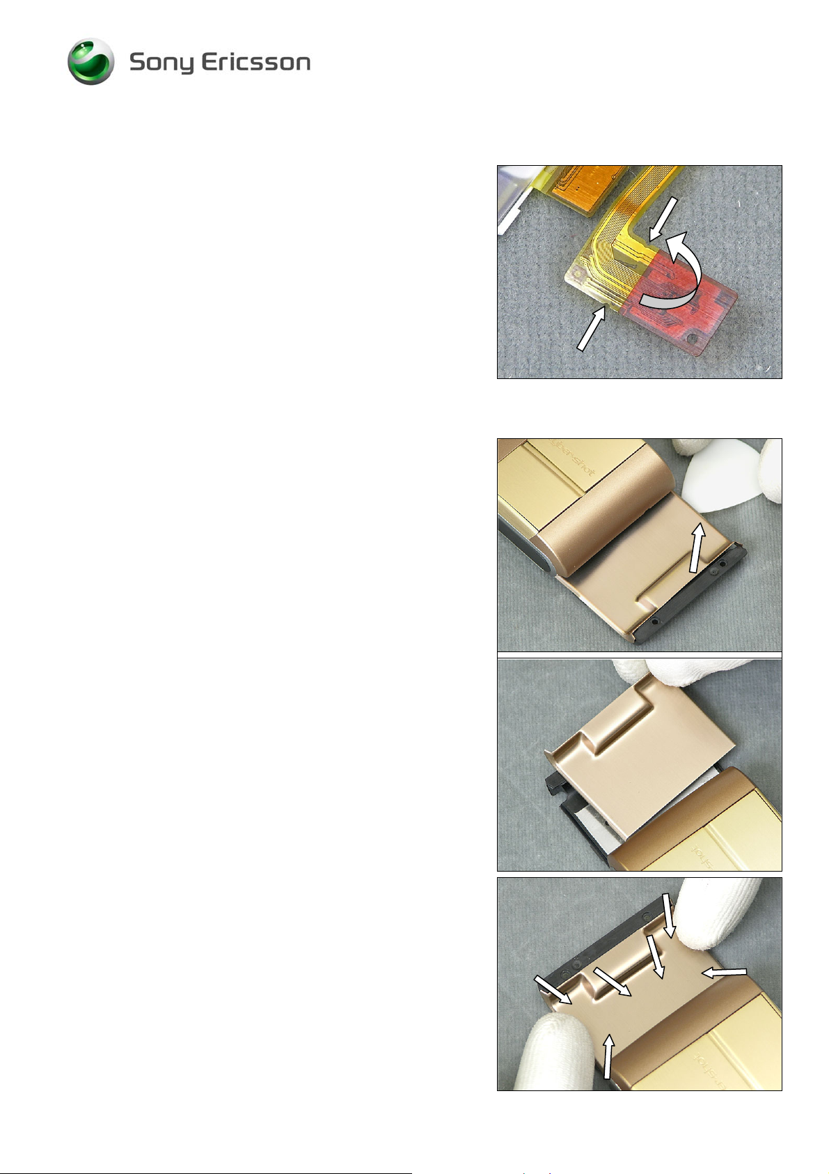
Fold the Slider FPC Assy along the white line.
(Slider FPC Assy not mounted for visibility)
Attach the Slider FPC Assy to the Main PBA..
The white line shall not be visible when looking from above
Use your fingers to thread the Slider FPC Assy through the
gap
B
E VERY CAREFUL NOT TO DAMAGE THE SLIDER FPC ASSY!
1218-1731 Rev 3 73(87)
Company Internal
© Sony Ericsson Mobile Communi cat i ons AB
Page 74

Working Instruction, Mechanical
Use your fingers to position the Main PBA
M
AKE SURE THE NUMERIC KEY FOIL IS POSITIONED
CORRECTLY WHEN POSITIONING THE
MAIN PBA!
Use a Front Opening Tool and your fingers to position the
Main PBA.
B
E VERY CAREFUL NOT TO DAMAGE THE MAIN PBA SWITCHES
BY USING A FRONT OPENING TOOL AND BENDING OUT THE
CARRIER BASE ASSY!
Use a Flex Film Assembly Tool to attach the connector to
the Main PBA
ENSURE
THAT THERE IS A GOOD CONNECTION!
Use a Flex Film Assembly Tool to position the Key Camera
Flex in the camera key switch supporter
1218-1731 Rev 3 74(87)
Company Internal
© Sony Ericsson Mobile Communi cat i ons AB
Page 75

Working Instruction, Mechanical
Use a Flex Film Assembly Tool to position and attach the
BT/WLAN Antenna
M
AKE SURE THE BT/WLAN ANTENNA IS COMPLETELY HELD
BY THE CLIP
!
1218-1731 Rev 3 75(87)
Company Internal
© Sony Ericsson Mobile Communi cat i ons AB
Page 76

Working Instruction, Mechanical
4.5 Cover Base Rear Assembly
Use your fingers to position the Cover Base Rear
Assembly.
Use your fingers to snap on the Cover Base Rear
Assembly.
Use a Screwdriver with T6 Bit to assemble the two Screws
Torx 5.3x1.6 (torque 11Ncm).
Use a Screwdriver with T5 Bit to assemble the two Screws
Torx 5.0x1.6 (torque 11Ncm).
1218-1731 Rev 3 76(87)
Company Internal
© Sony Ericsson Mobile Communi cat i ons AB
Page 77

Working Instruction, Mechanical
4.6 Cover Rear Assembly
Use your fingers to position the Cover Rear Assembly
Use a Screwdriver with JCIS Bit (torque 11Ncm) to insert
and tighten the four Flat Head M1.4x1.7
4.7 PBA Key Flex Flip Complete
ENSURE THAT THERE IS A SPACER FOR RIGID FLEX
FIXATION MOUNTED!
Align the Spacer for Rigid Flex Fixation with the “golden”
line at the corner.
Use a Flex Film Assembly Tool to connect the PBA Key
Flex Flip Complete to the Slider FPC Assy
ENSURE
1218-1731 Rev 3 77(87)
Company Internal
THAT THERE IS A GOOD CONNECTION!
© Sony Ericsson Mobile Communi cat i ons AB
Page 78

Working Instruction, Mechanical
Use a Front Opening Tool to snap on the PBA Key Flex Flip
Complete to Slider FPC Assy
MAKE SURE TO ALIGN THE PBA KEY FLEX FLIP COMPLETE
PROPERLY TO THE
COVER REAR ASSY!
Use your fingers to attach Key A and Key B
U
SE THE GUIDE PINS ON THE COVER REAR ASSY TO ALIGN
KEY A AND KEY B!
Use your fingers to attach the GPS Antenna
1218-1731 Rev 3 78(87)
Company Internal
© Sony Ericsson Mobile Communi cat i ons AB
Page 79

Working Instruction, Mechanical
Use your fingers to attach the PBA Key Flex Flip Complete.
Use a Flex Film Assembly Tool to position the Foil Adhesive
Single Side 0.15 mm Flip Tape
MAKE SURE THE ALIGNMENT IS CORRECT!
Use your fingers to attach the Foil Adhesive Single Side
0.15 mm Flip Tape
1218-1731 Rev 3 79(87)
Company Internal
© Sony Ericsson Mobile Communi cat i ons AB
Page 80

Working Instruction, Mechanical
4.8 LCD Support Sheet
Use a blunt pair of Tweezers and your fingers to attach the
LCD Support Sheet.
1218-1731 Rev 3 80(87)
Company Internal
© Sony Ericsson Mobile Communi cat i ons AB
Page 81

Working Instruction, Mechanical
4.9 Display 2.41 TFT
Use your fingers to position the Display 2.41 TFT.
Attach the connector to the PBA Key Flex Flip Complete
ENSURE
MAKE SURE THE PBA KEY FLEX FLIP COMPLETE IS
PROPERLY ALIGNED AS THE PICTURE SHOWS
THAT THERE IS A GOOD CONNECTION!
!
Locate the three snap hooks and use your fingers to flip
over and place the PBA Key Flex Flip Complete.
1218-1731 Rev 3 81(87)
Company Internal
© Sony Ericsson Mobile Communi cat i ons AB
Page 82

Working Instruction, Mechanical
4.10 Cover Flip Front
Use your fingers to position the Cover Flip Front in the rear
end.
Use your fingers to snap on the Cover Flip Front.
Use your fingers to slide and position the Cover Flip Front
to make the two Screw 2.3x1.4 holes visible through the two
holes in the Cover Base Rear Assembly.
Use a Screwdriver with JCIS Bit (torque 11Ncm) to insert
and tighten the two Screw 2.3x1.4.
1218-1731 Rev 3 82(87)
Company Internal
© Sony Ericsson Mobile Communi cat i ons AB
Page 83

Working Instruction, Mechanical
4.11 Cap Plastic RF Numeric Keyboard & Cap Numeric
Keyboard
Use a pair of ESD tweezers to place the Cap Plastic RF
Keyboard Numeric.
Use a pair of ESD tweezers to place the Cap Numeric
Keyboard.
1218-1731 Rev 3 83(87)
Company Internal
© Sony Ericsson Mobile Communi cat i ons AB
Page 84

Working Instruction, Mechanical
4.12 Keyboard
Use a Flex Film Assembly Tool to position the Keyboard.
Place the phone on the Keyboard Pressure Tool as the
picture shows. Set the Pressure Tool to 50 N.
FIND THE USER GUIDE FOR THE PRESSURE TOOL IN
CSPN/R
CATALOGUE (SPACE ID 1003-9107)
OPEN ZIP FILE/ PDF DOCUMENT SPACE ID 1219-2553
EPAIR INSTRUCTIONS/MECHANICAL/TOOL
Use the Pressure Tool to attach the Keyboard
Use the Pressure Tool to press the Keyboard for 10
seconds.
1218-1731 Rev 3 84(87)
Company Internal
© Sony Ericsson Mobile Communi cat i ons AB
Page 85

Working Instruction, Mechanical
4.13 Foil Flip Inner
Use a Screwdriver with JCIS Bit (torque 11Ncm) to insert
and tighten the two Screws 4.0x1.4.
Use a pair of ESD Tweezers to position and attach the Foil
Flip Inner.
4.14 Battery Cover & Battery
Use your fingers to attach the Battery.
Use your fingers to attach the Battery Cover.
1218-1731 Rev 3 85(87)
Company Internal
© Sony Ericsson Mobile Communi cat i ons AB
Page 86

Working Instruction, Mechanical
5 Country of Origin Barcodes for Brazil/VIVO
Labels
Below is a link to a list of countries of origin. If you are printing a Brazil or VIVO label, scan the
barcode corresponding to the correct country of origin for the “Fabricado” field.
1218-1731 Rev 3 86(87)
Company Internal
© Sony Ericsson Mobile Communi cat i ons AB
Page 87

Working Instruction, Mechanical
6 Revision history
Rev. Date Changes / Comments
1 2008-10-24 First release
2 2008-11-04 Chapter 1.1, 2.2, 2.5, 2.10, 4.4, 4.6, 4.8 changed
3 2008-11-20 Spacer for Rigid Flex Fixation added, and revised text
1218-1731 Rev 3 87(87)
Company Internal
© Sony Ericsson Mobile Communi cat i ons AB
 Loading...