

Page 1

Working Instruction, Mechanical
Working Instruction, Mechanical
Applicable for C702, C702a & C702c
CONTENTS
1213-5329 2
Company Internal
1 Introduction........................................
.....................................3
1.1 Equipment.....................................................................4
1.2 General cautions ..........................................................5
1.3 Adhesives......................................................................5
2 Disassembly............................................................................6
2.1 Overview........................................................................6
2.1.1 Battery Cover and Battery.....................................................7
2.1.2 Screw Cover Assembly.........................................................9
2.1.3 Frame Assembly .................................................................11
2.1.4 M2 Cover & Front Cover Assembly.....................................13
2.1.5 Speaker Box & Antenna Assembly......................................15
2.1.6 LCD Frame Assembly.........................................................17
3 Replacements........................................................................21
3.1 Battery Cover..............................................................22
3.2 Battery .........................................................................22
3.3 Screw Cover................................................................
3.4 Frame...........................................................................22
3.5 M2 Cover and Front Cover.........................................22
3.6 Speaker Box and Antenna.........................................22
3.7 LCD Frame ..................................................................22
3.8 Vibrator........................................................................23
3.9 Main Rubber Ring.......................................................24
3.10 Volume Key.................................................................25
3.11 Camera Key.................................................................26
3.12 On/Off Key...................................................................27
3.13 RF Hole Adhesive.......................................................28
3.14 BT Antenna .................................................................29
3.15 ESD Gasket .................................................................30
3.16 Main Keypad Cover ....................................................31
3.17 Co-Brand Label...........................................................33
3.18 Main Keypad ...............................................................34
3.19 Flash FPC....................................................................
3.20 Main Antenna..............................................................36
3.21 Keyboard.....................................................................
3.22 Receiver.......................................................................40
3.23 LCD Gasket .................................................................41
Sony Ericsson Mobile Communications AB
22
35
38
1
(58)
Page 2

Working Instruction, Mechanical
3.24 Sony Ericsson Icon ....................................................42
3.25 3.2 MP AF Camera ......................................................43
3.26 Speaker Box Gasket...................................................45
3.27 Receiver Gasket..........................................................46
3.28 Liquid Intrusion Indicator ..........................................47
3.29 Label ............................................................................48
4 Reassembly...........................................................................49
4.1 Overview......................................................................49
4.1.1 Speaker Box Assy & PCBA.................................................50
4.1.2 LCD frame Assy & PCBA....................................................51
4.1.3 Front Cover Assy.................................................................52
4.1.4 M2 Cover.............................................................................53
4.1.5 Frame Assy.........................................................................54
4.1.6 Screw Cover Assy...............................................................55
4.1.7 Battery & Battery Cover.......................................................56
5 Revision history....................................................................58
1213-5329 2
2(58)
Sony Ericsson Mobile Communications AB
Page 3
Working Instruction, Mechanical
1 Introduction
C702
1213-5329 2
Company Internal
Sony Ericsson Mobile Communications AB
3(58)
Page 4
Working Instruction, Mechanical
1.1 Equipment
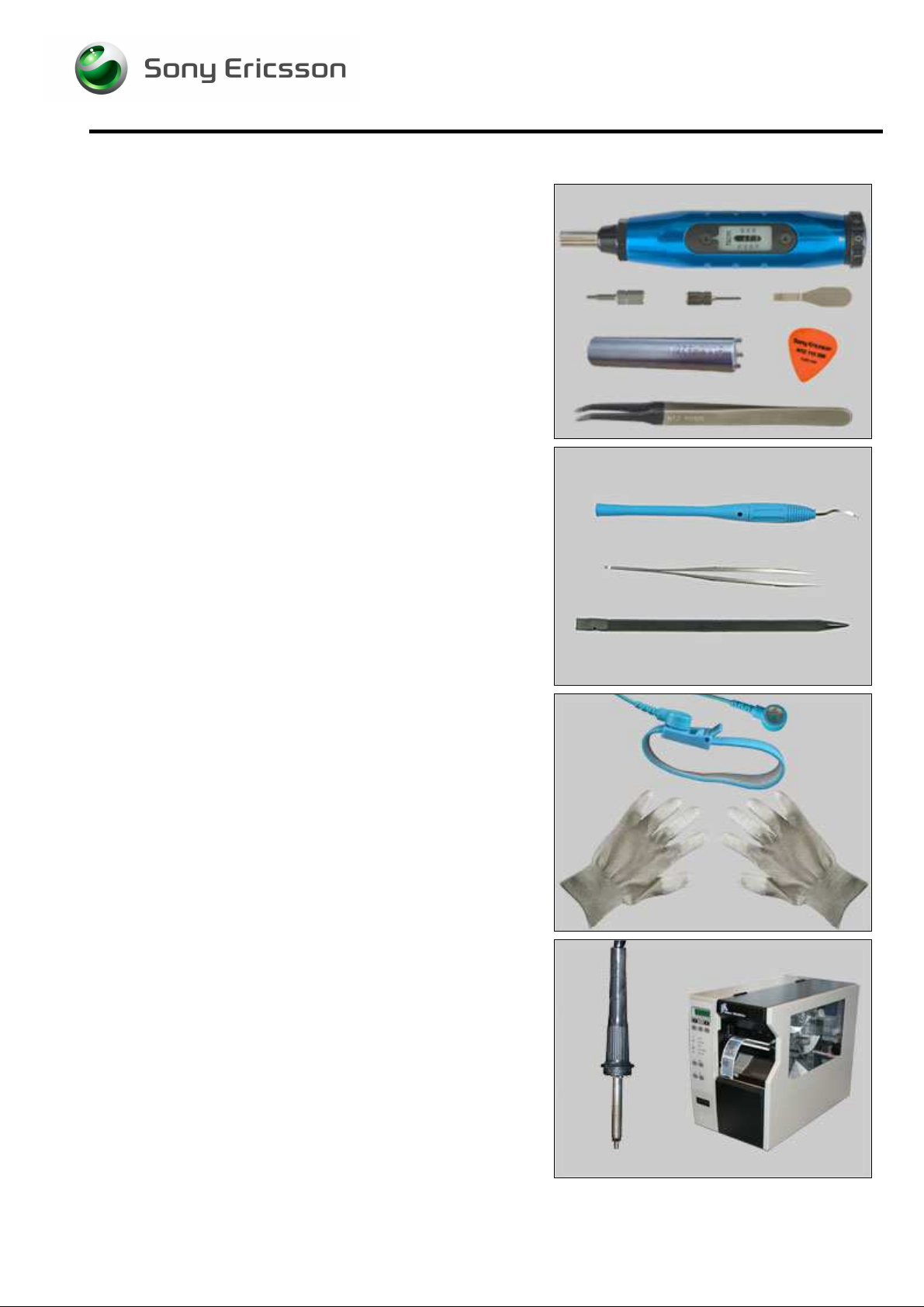
SPECIAL TOOLS
Special tools:
• NTZ 122 459 Torque Screwdriver (or equivalent)
• NTZ 122 288 Torx Bits No. 6
• NTZ 112 1052 JCIS No. 0 Screw Bit
• NTZ 112 302/2 Front Opening Tool
• 1206-7115 Camera removal tool
• NTZ 112 590 Guitar Pick
• NTZ 122 521 Flex Film Assembly Tool
STANDARD TOOLS
Standard tools have to be locally purchased
• Dentist Hook
• ESD Tweezers
• Nylon Pointer
ESD EQUIPMENT
Protect the phone from ESD damages whenever it has
been opened by using:
• ESD-Wristband
• ESD-Gloves
LABEL EQUIPMENT
The following special equipment is required when replacing
or installing a new Label:
• Hot Air Flow Solder Station
• Zebra Printer connected to Computer
1213-5329 2
Company Internal
Sony Ericsson Mobile Communications AB
4(58)
Page 5

Working Instruction, Mechanical
1.2 General cautions
The following cautions are considered to be generic for all phone models and will not be repeated in
the Disassembly, Replacements and Reassembly sections:
• SWITCH OFF THE PHONE AND REMOVE ANY MEMORY STICK BEFORE THE START OF THE DISASSEMBLY!
• KEEP ALL CONTACT SURFACES CLEAN!
• BE CAREFUL WHEN USING TOOLS LIKE THE DENTIST HOOK, TWEEZERS, OPENING TOOLS, GUITAR PICK
ETC. TO AVOID SCRATCHES OR DAMAGES TO THE EXTERIOR AND INTERIOR PARTS OF THE PHONE!
E CAREFUL NOT TO DAMAGE ANY CONTACT SPRINGS!
• B
• REMEMBER TO REMOVE THE PROTECTION FOILS ON NEW PARTS SUCH AS THE FRONT COVER AND LCD!
• NEVER TOUCH THE DISPLAY GLASS!
• USE AIR BLOW EQUIPMENT TO KEEP THE FRONT WINDOW AND DISPLAY MODULE DUST FREE!
1.3 Adhesives
Use Dentist Hook and/or Tweezers to remove the old Adhesives.
Clean the surface with isopropyl alcohol before attaching the new Adhesives.
1213-5329 2
Company Internal
Sony Ericsson Mobile Communications AB
5(58)
Page 6
Start
Done
Working Instruction, Mechanical
2 Disassembly
When you are going to replace a part being listed in Replacements, the instruction of that section
usually begins by directing you to this Disassembly section with a specification of the instructions you
have to carry out in order to disassemble the phone as far as needed before returning to
Replacements for the actual replacement.
REPLACEMENTS
Contents
page
DISASSEMBLY
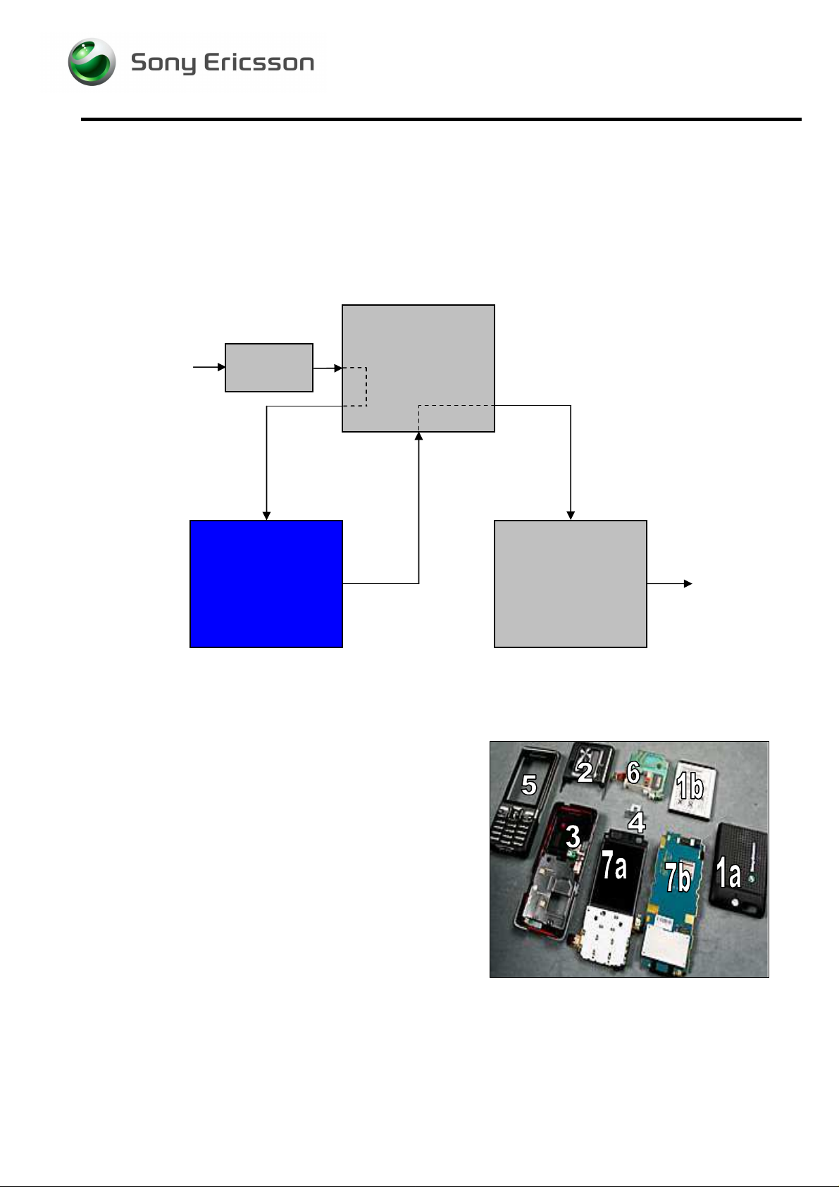
2.1 Overview
The disassembly is done in the following sequence:
1. Battery Cover (a) Battery (b)
2. Screw Cover Assy
3. Frame Assy
4. M2 Cover
5. Front Cover Assy
6. Speaker Box & Antenna
7. LCD Frame Assy (a) PCBA (b)
REASSEMBLY
1213-5329 2
Company Internal
6(58)
Sony Ericsson Mobile Communications AB
Page 7
Working Instruction, Mechanical
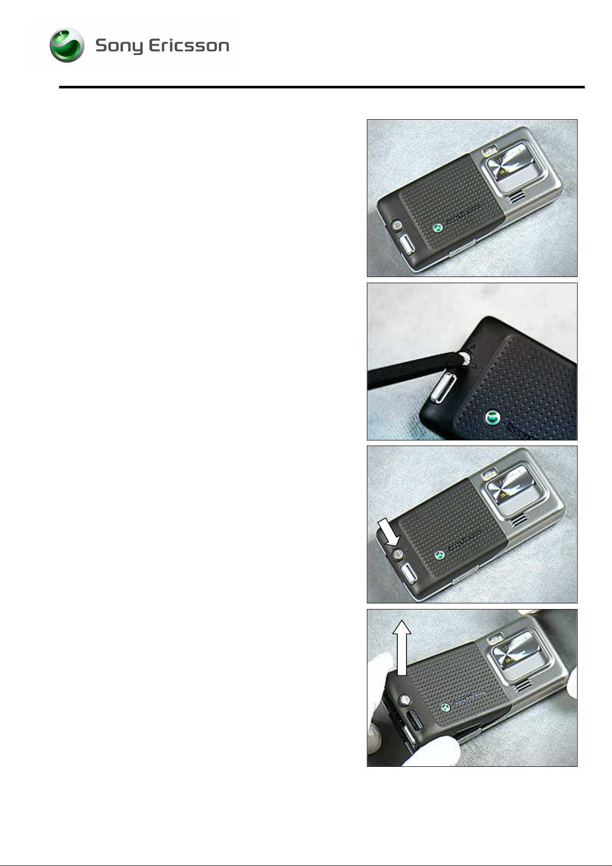
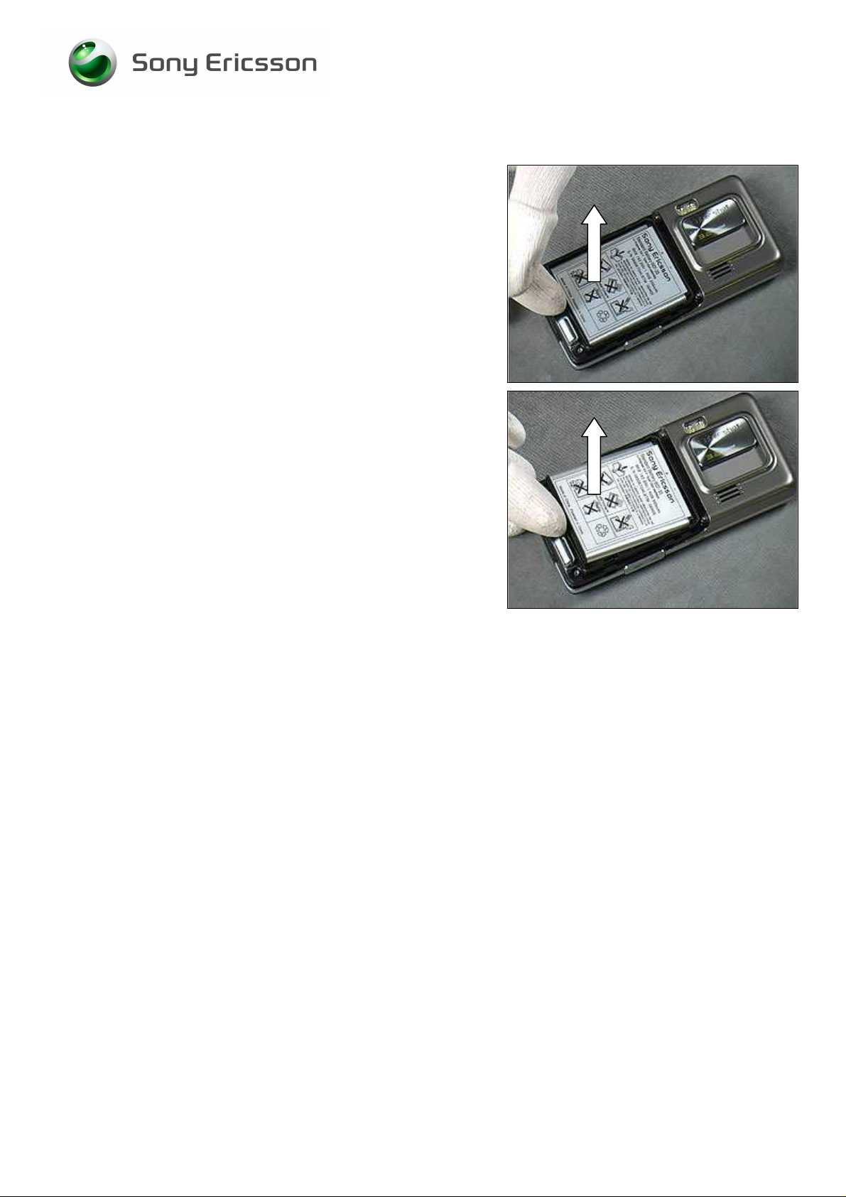
2.1.1 Battery Cover and Battery
Prepare to release the Battery Cover.
Use Nylon Pointer to turn the Latch anticlockwise.
Unlock the Latch as shown in picture.
Lift up the Battery Cover at the bottom end.
1213-5329 2
Company Internal
Sony Ericsson Mobile Communications AB
7(58)
Page 8
Working Instruction, Mechanical
Battery continued
Grip the Battery at the bottom end using fingers.
Lift up the Battery at the bottom end and remove it.
1213-5329 2
8(58)
Sony Ericsson Mobile Communications AB
Page 9
Working Instruction, Mechanical
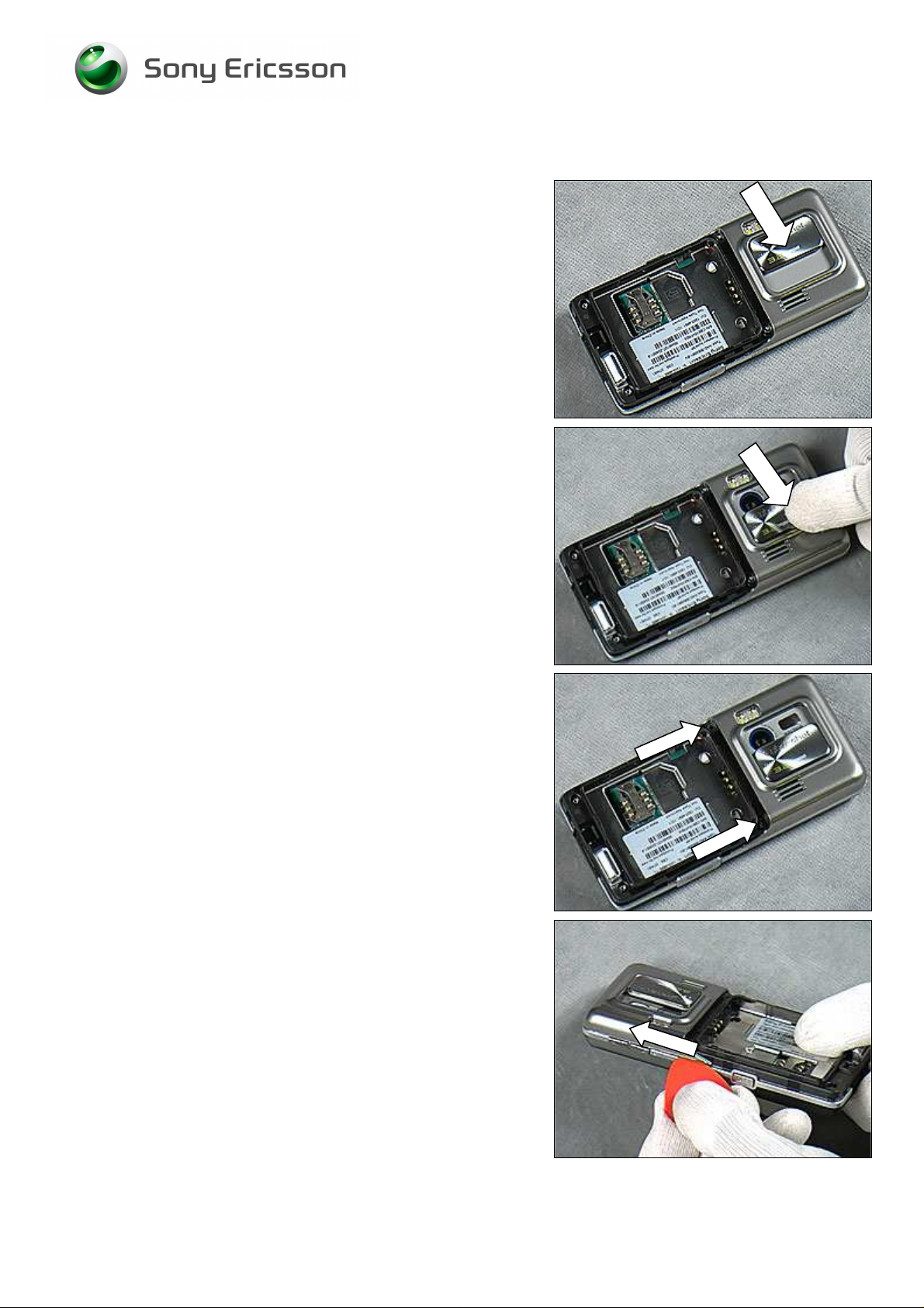
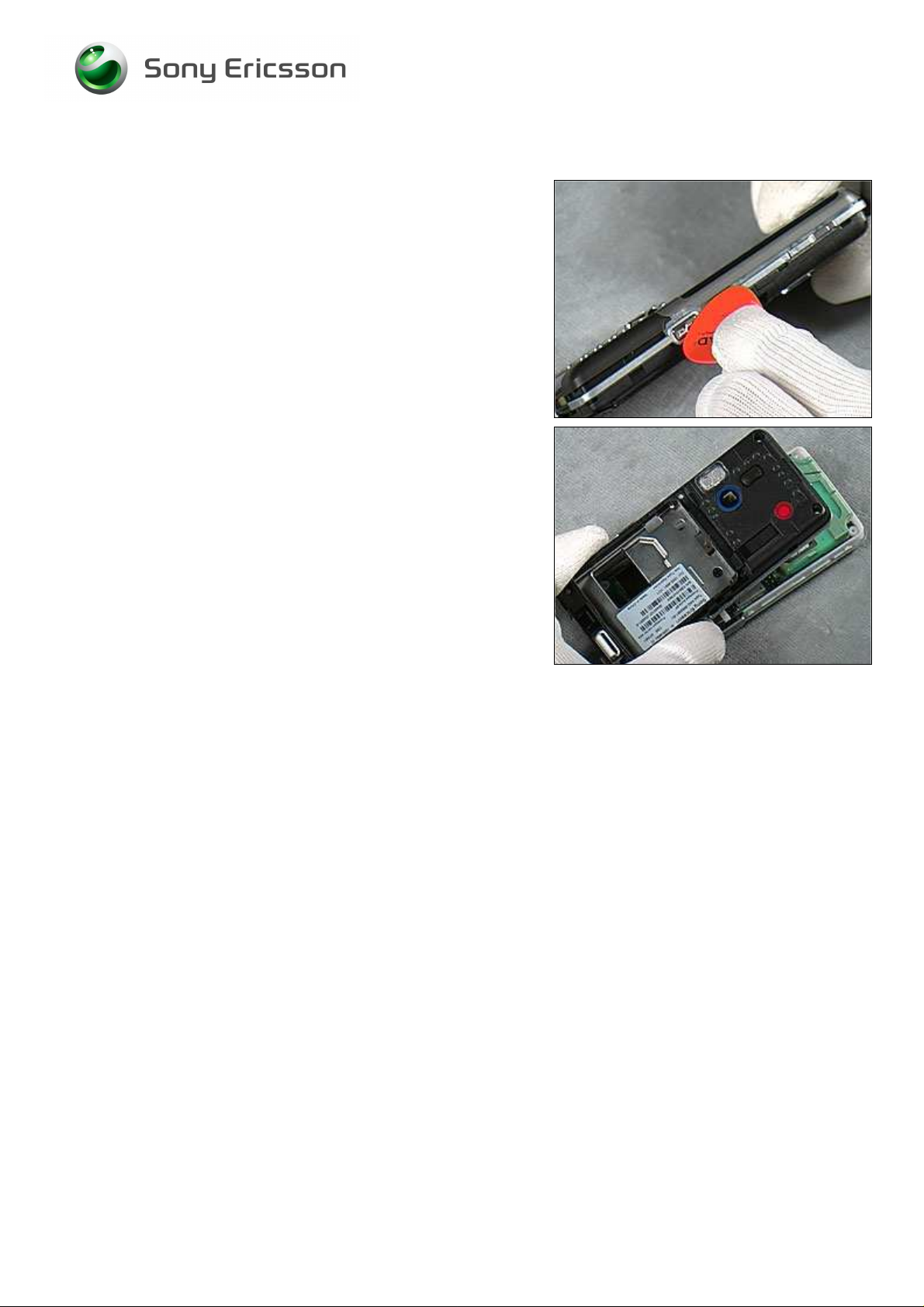
2.1.2 Screw Cover Assembly
Slide the Camera Lens Cover.
Open the Camera Lens Cover using fingers.
OPEN THE CAMERA LENS COVER BEFORE STARTING
DISASSEMBLY! OTHERWISE, THE CONTACT SPRINGS WILL BE
DAMAGED DURING DISASSEMBLY!
Remove the two Screws using JCIS No.0 Screw Bit.
Insert Guitar Pick as shown in picture and unlatch the snap
hooks along the left side of the Screw Cover Assy as shown
by the arrow.
IF NECESSARY, SLIDE BACK AND FORTH UNTIL ALL HOOKS ARE
UNLATCHED!
1213-5329 2
Sony Ericsson Mobile Communications AB
9(58)
Page 10
Working Instruction, Mechanical
Screw Cover Assembly continued
Repeat this at the right side.
Slide along the top to unlatch the snap hooks.
TAKE CARE WHEN REMOVING THE SCREW COVER THAT WATER
DOES FLOW OFF SCREW COVER INTO THE PHONE BACK COVER
AREA!
Carefully lift up the Screw Cover Assy.
1213-5329 2
Sony Ericsson Mobile Communications AB
10(58)
Page 11
Working Instruction, Mechanical
2.1.3 Frame Assembly
CHECK FIRSTLY IF THE M2 MEMORY STICK HAS BEEN
REMOVED BEFORE CONTINUING!
Use Torx bit no. 6 to remove the four screws.
Insert the Guitar Pick at the left bottom as shown in picture
and slide along the side to unlatch the snap hooks.
IF NECESSARY, SLIDE BACK AND FORTH UNTIL ALL THE HOOKS
ARE UNLATCHED!
Repeat this for the left side.
Repeat this for the right bottom.
1213-5329 2
Sony Ericsson Mobile Communications AB
11(58)
Page 12
Working Instruction, Mechanical
Frame Assembly continued
Repeat this for the right side.
Lift up the Frame Assembly.
1213-5329 2
12(58)
Sony Ericsson Mobile Communications AB
Page 13
Working Instruction, Mechanical
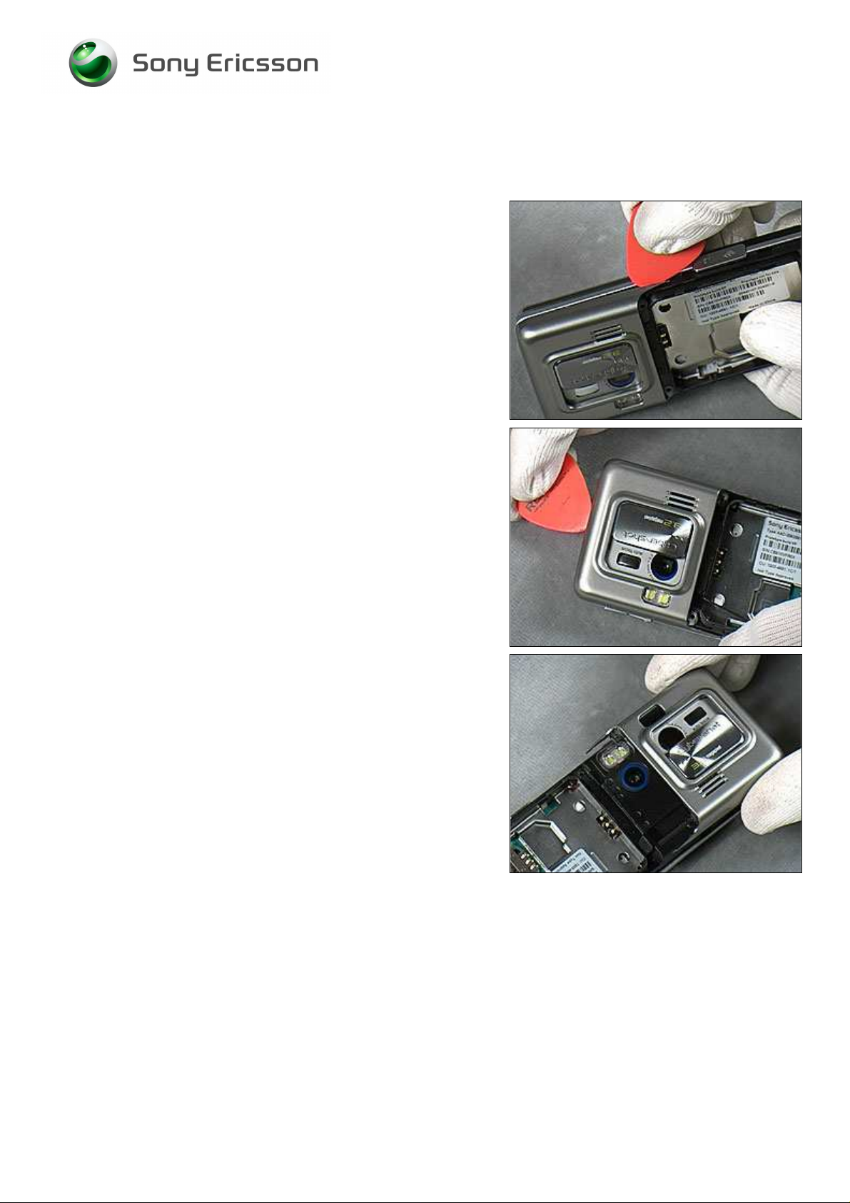
2.1.4 M2 Cover & Front Cover Assembly
Push the M2 Cover using Front Opening Tool or fingers.
Pull out the M2 Cover using Flex Film Assembly Tool or
fingers.
Insert the Nylon Pointer at the right side as shown in picture
to loose the Core Unit from the Front Cover Assy.
Insert the Front Opening Tool at the left side as shown in
picture to loosen the Core Unit from the Front Cover Assy.
1213-5329 2
Sony Ericsson Mobile Communications AB
13(58)
Page 14
Working Instruction, Mechanical
Front Cover continued
Remove the Core Unit by lifting it up from the top as shown
by the arrow.
Gently remove the Core Unit from the Front Cover.
1213-5329 2
14(58)
Sony Ericsson Mobile Communications AB
Page 15
Working Instruction, Mechanical
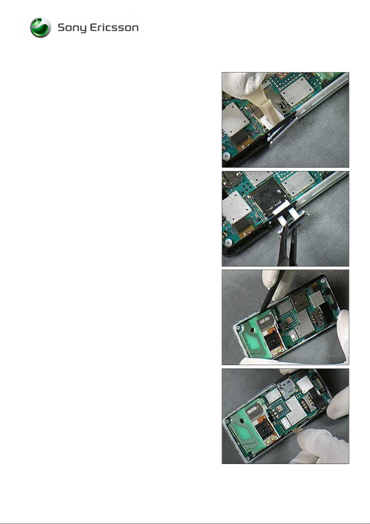
2.1.5 Speaker Box & Antenna Assembly
Insert the Front Opening Tool to unlatch the right side
hooks between the Speaker Box and the PCBA.
Insert Front Opening Tool to unlatch the right top hooks
between the Speaker Box and the PCBA.
Insert Front Opening Tool to unlatch the left side hooks
between the Speaker Box and the PCBA.
Lift up the Speaker Box from the PCBA.
1213-5329 2
Sony Ericsson Mobile Communications AB
15(58)
Page 16
Working Instruction, Mechanical
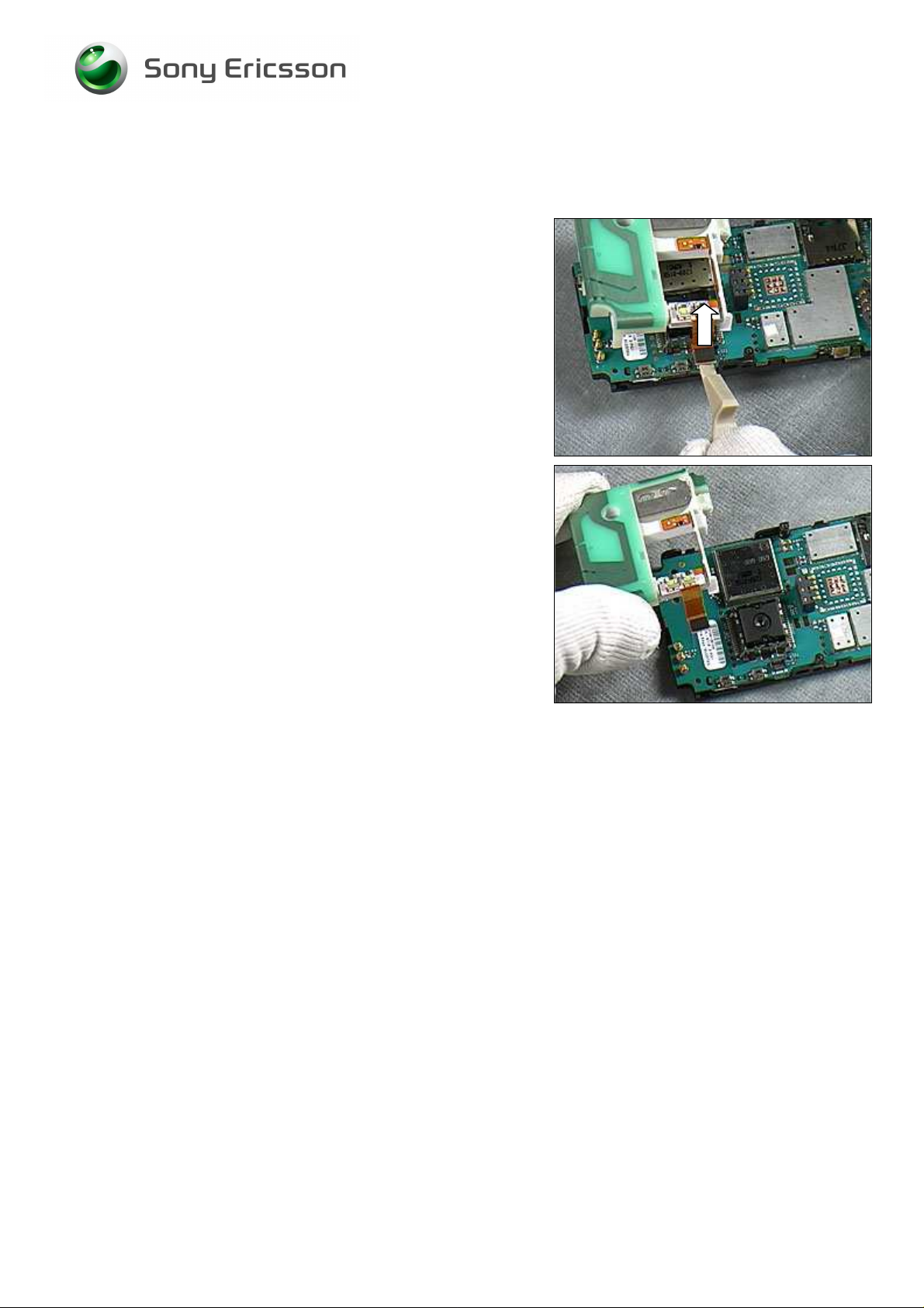
Speaker Box & Antenna Assembly continued
Use the Front Opening Tool to unlatch the Flash FPC
Connector as the arrow shows in the picture.
Gently remove the Speaker Box from the PCBA.
1213-5329 2
16(58)
Sony Ericsson Mobile Communications AB
Page 17
Working Instruction, Mechanical
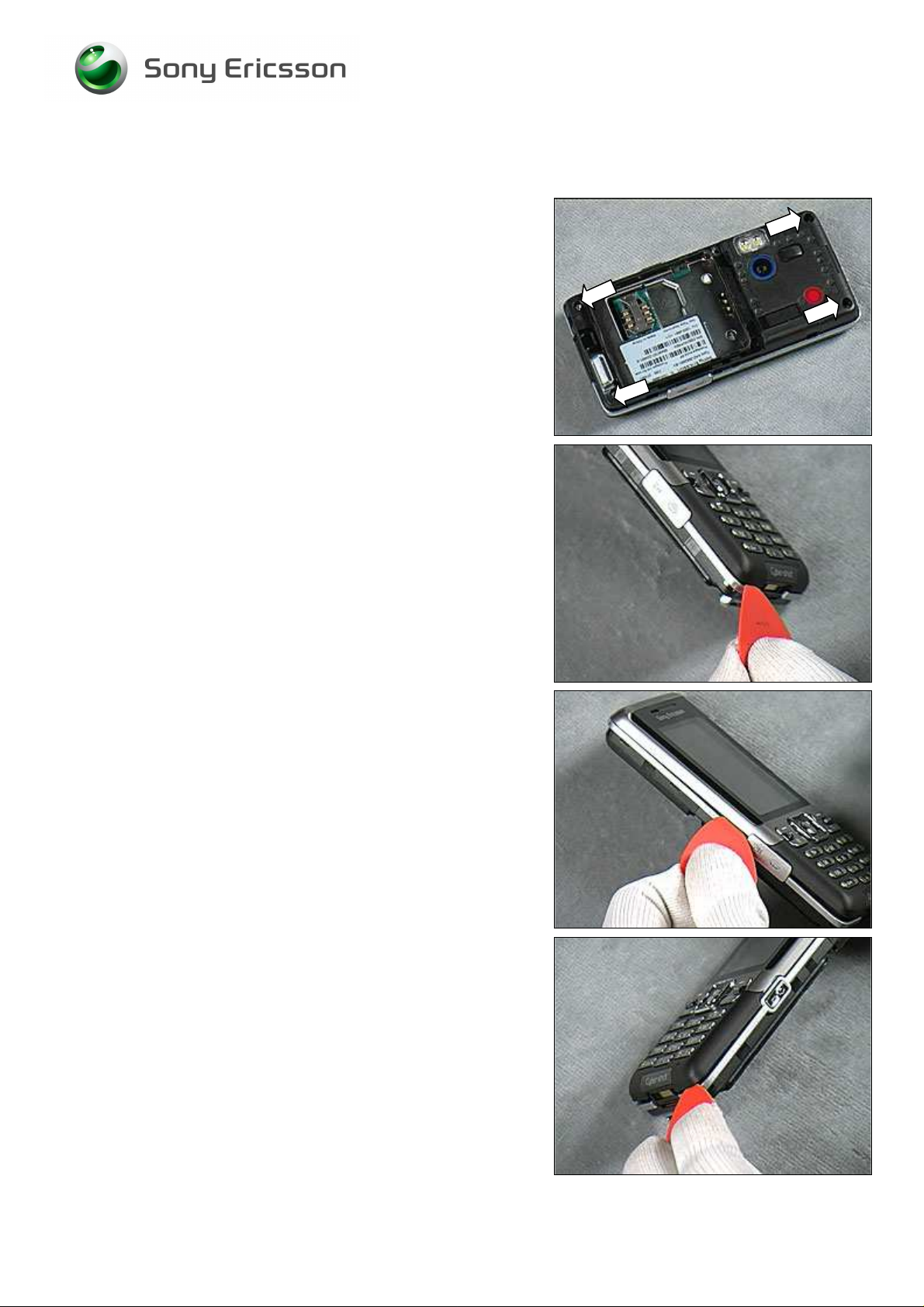
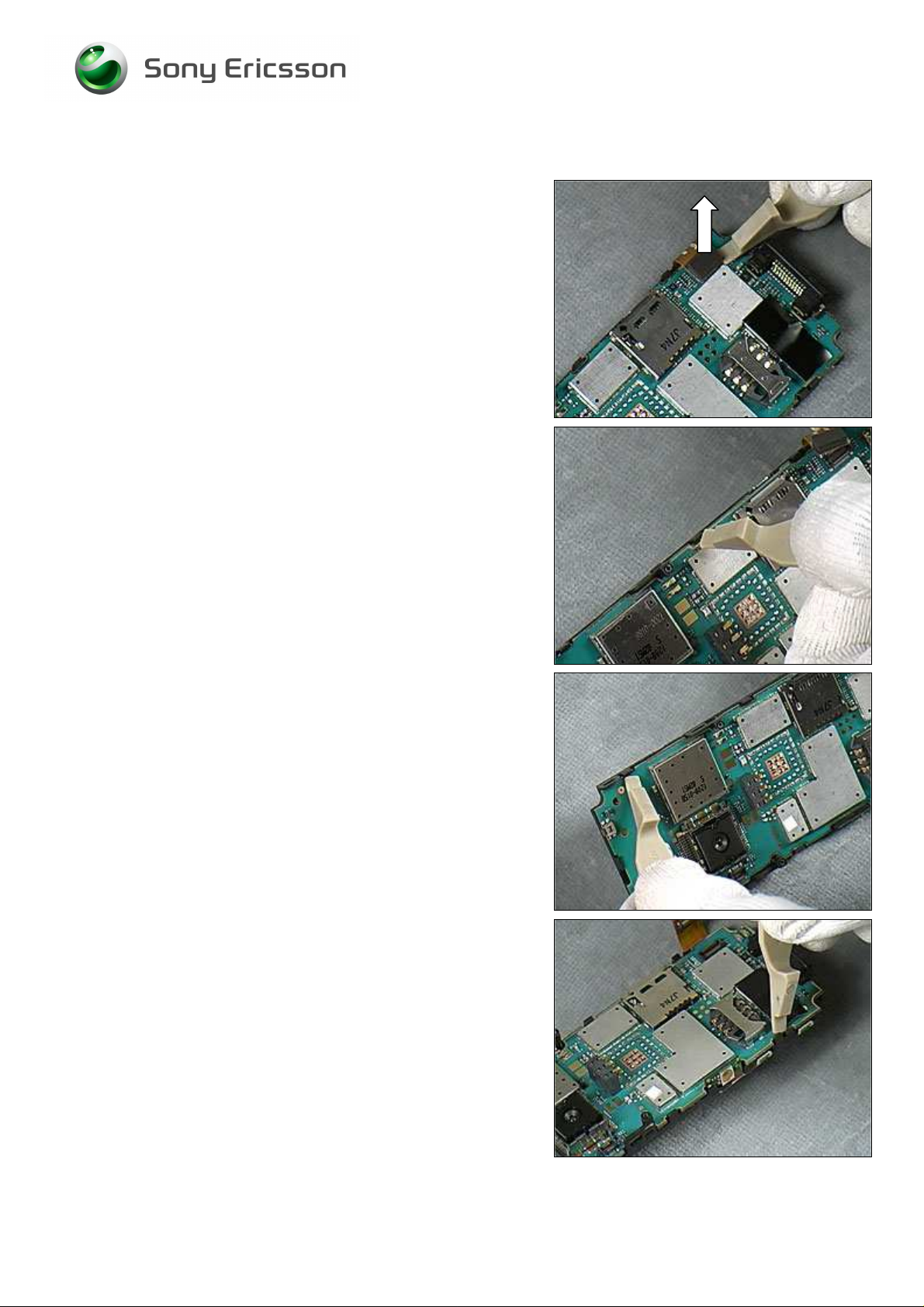
2.1.6 LCD Frame Assembly
Insert the Front Opening Tool to unlatch the LCD Connector
as shown in the picture.
Insert the Front Opening Tool to release the right side hook
between the PCBA and the LCD Frame.
Insert the Front Opening Tool to release the right top Hook
between the PCBA and the LCD Frame.
Insert the Front Opening Tool to release the left bottom
hook between the PCBA and the LCD Frame.
1213-5329 2
Sony Ericsson Mobile Communications AB
17(58)
Page 18
Working Instruction, Mechanical
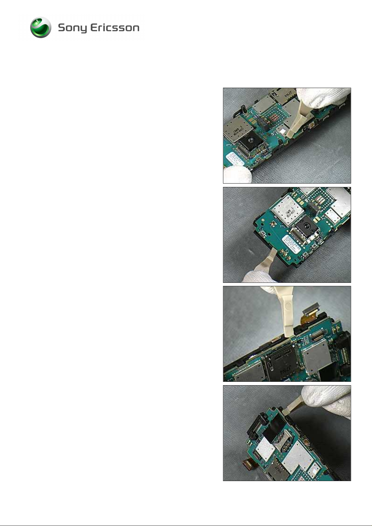
LCD Frame continued
Insert the Front Opening Tool to release the left middle
hooks between the PCBA and the LCD Frame.
Insert the Front Opening Tool to release the top hooks
between the PCBA and the LCD Frame.
Insert the Front Opening Tool to release the right middle
hooks between the PCBA and the LCD Frame.
BE CAREFUL WHEN UNLATCHING THE LAST HOOK - THE LCD
FRAME CAN JUMP OFF THE PCBA!
Insert the Front Opening Tool to release the left bottom
hooks between the PCBA and the LCD Frame.
1213-5329 2
18(58)
Sony Ericsson Mobile Communications AB
Page 19

Working Instruction, Mechanical
LCD Frame continued
Check that all snap hooks between the PCBA and the LCD
Frame are unlatched.
Lift up the PCBA from the LCD Frame.
BE CAREFUL NOT TO DAMAGE THE LCD FLEX!
Find the LCD Connector between the PCBA and the LCD
Frame.
Use the Front Opening Tool to release the LCD Connector.
1213-5329 2
Sony Ericsson Mobile Communications AB
19(58)
Page 20

Working Instruction, Mechanical
LCD Frame continued
Lift up the LCD Frame from the PCBA.
1213-5329 2
20(58)
Sony Ericsson Mobile Communications AB
Page 21

Start
Done
Working Instruction, Mechanical
3 Replacements
Search for the part to be replaced on the Contents page and go to that instruction to be found in this
Replacements section.
The instruction usually begins by directing you to the Disassembly section with a specification of the
instructions you have to carry out in order to disassemble the phone as far as needed before the
actual replacement.
Go back to this Replacements section and carry out the instruction.
The instruction usually ends by directing you to the Reassembly section with a specification of the
instructions you have to carry out in order to reassemble the phone.
REPLACEMENTS
Contents
page
DISASSEMBLY REASSEMBLY
1213-5329 2
Company Internal
21(58)
Sony Ericsson Mobile Communications AB
Page 22

Working Instruction, Mechanical
3.1 Battery Cover
Follow the 2.1.1 Disassembly instructions!
Prepare a Battery Cover.
Follow the 4.1.7 Reassembly instructions!
3.2 Battery
Follow the 2.1.1 Disassembly instructions!
Prepare a Battery.
Follow the 4.1.7 Reassembly instructions!
3.3 Screw Cover
Follow the 2.1.1 – 2.1.2 Disassembly instructions!
Prepare a Screw Cover.
Follow the 4.1.6 – 4.1.7 Reassembly instructions!
3.4 Frame
Follow the 2.1.1 – 2.1.3 Disassembly instructions!
Prepare a Frame.
Follow the 4.1.5 – 4.1.7 Reassembly instructions!
3.5 M2 Cover and Front Cover
Follow the 2.1.1 – 2.1.4 Disassembly instructions!
Prepare a M2 Cover and a Front Cover.
Follow the 4.1.4 – 4.1.7 Reassembly instructions!
3.6 Speaker Box and Antenna
Follow the 2.1.1 – 2.1.5 Disassembly instructions!
Prepare a Speaker Box and an Antenna.
Follow the 4.1.1 – 4.1.7 Reassembly instructions!!
3.7 LCD Frame
Follow the 2.1.1 – 2.1.6 Disassembly instructions!
Prepare a LCD Frame.
Follow the 4.1.2 – 4.1.7 Reassembly instructions!
1213-5329 2
Company Internal
Sony Ericsson Mobile Communications AB
22(58)
Page 23

Working Instruction, Mechanical
3.8 Vibrator
REMOVAL
Follow the 2.1.1 – 2.1.3 Disassembly instructions!
Remove the Vibrator with Flex Film Assembly Tool or
Tweezers.
VOID TOUCHING METAL CONTACTS!
A
INSTALLATION
Place the Vibrator in the cavity.
Position into place using Tweezers.
Follow the 4.1.5 - 4.1.7 Reassembly instructions!
1213-5329 2
Company Internal
Sony Ericsson Mobile Communications AB
23(58)
Page 24

Working Instruction, Mechanical
3.9 Main Rubber Ring
REMOVAL
Follow 2.1.1 – 2.1.3 Disassembly instructions!
Use Dentist Hook to lift the Main Rubber Ring from the
Frame.
Use the Dentist Hook to remove the Main Rubber Ring.
INSTALLATION
Mount the Main Rubber Ring with the three points shown by
the arrows in picture.
Follow 4.1.5 - 4.1.7 Reassembly instructions!
1213-5329 2
24(58)
Sony Ericsson Mobile Communications AB
Page 25

Working Instruction, Mechanical
3.10 Volume Key
REMOVAL
Follow 2.1.1 – 2.1.3 Disassembly instructions!
Remove the Volume Key using Flex Film Assembly Tool or
Tweezers.
INSTALLATION
Place the Volume Key using Flex Film Assembly Tool or
Tweezers.
Position into place.
Follow 4.1.5 – 4.1.7 Reassembly instructions!
1213-5329 2
25(58)
Sony Ericsson Mobile Communications AB
Page 26

Working Instruction, Mechanical
3.11 Camera Key
REMOVAL
Follow 2.1.1 – 2.1.3 Disassembly instructions!
Use Flex Film Assembly Tool to remove the Camera Key.
INSTALLATION
Use Flex Film Assembly Tool to position the Camera Key.
Follow 4.1.5 - 4.1.7 Reassembly instructions!
1213-5329 2
Sony Ericsson Mobile Communications AB
26(58)
Page 27

Working Instruction, Mechanical
3.12 On/Off Key
REMOVAL
Follow 2.1.1 – 2.1.3 Disassembly instructions!
Use Flex Film Assembly Tool or Tweezers to remove the
On/Off Key.
INSTALLATION
Use Flex Film Assembly Tool to position the On/Off Key.
Follow 4.1.5 - 4.1.7 Reassembly instructions!
1213-5329 2
Sony Ericsson Mobile Communications AB
27(58)
Page 28

Working Instruction, Mechanical
3.13 RF Hole Adhesive
REMOVAL
Follow 2.1.1 – 2.1.3 Disassembly instructions!
Use Dentist Hook to remove the old RF Hole Adhesive.
INSTALLATION
ALWAYS USE NEW RF HOLE ADHESIVE!
Use Flex Film Assembly Tool to position the new RF Hole
Adhesive.
Follow 4.1.5 - 4.1.7 Reassembly instructions!
1213-5329 2
Sony Ericsson Mobile Communications AB
28(58)
Page 29

Working Instruction, Mechanical
3.14 BT Antenna
REMOVAL
Follow 2.1.1 – 2.1.3 Disassembly instructions!
Use Tweezers to release the BT Antenna hooks.
Use Tweezers to remove the BT Antenna.
INSTALLATION
Use Flex Film Assembly Tool to position the BT Antenna.
Follow 4.1.5 - 4.1.7 Reassembly instructions!
1213-5329 2
Sony Ericsson Mobile Communications AB
29(58)
Page 30

Working Instruction, Mechanical
3.15 ESD Gasket
REMOVAL
Follow 2.1.1 – 2.1.3 Disassembly instructions!
Use Tweezers to remove the ESD Gasket.
INSTALLATION
Use Flex Film Assembly Tool to position the ESD Gasket.
Follow 4.1.5 - 4.1.7 Reassembly instructions!
1213-5329 2
Sony Ericsson Mobile Communications AB
30(58)
Page 31

Working Instruction, Mechanical
3.16 Main Keypad Cover
REMOVAL
Follow 2.1.1 - 2.1.4 Disassembly instructions!
Insert the Front Opening Tool at one side as shown in
picture to release the Main Keypad Cover from the Front
Cover.
Insert the Front Opening Tool at another side as shown in
picture to remove the Main Keypad Cover from the Front
Cover.
INSTALLATION
Grip the Main Keypad Cover using fingers.
Position the Main Keypad Cover at the top.
1213-5329 2
Sony Ericsson Mobile Communications AB
31(58)
Page 32

Working Instruction, Mechanical
Main Keypad Cover continued
Position the Main Keypad Cover at the bottom and snap it
into place.
Follow 4.1.3 - 4.1.7 Reassembly instructions!
1213-5329 2
32(58)
Sony Ericsson Mobile Communications AB
Page 33

Working Instruction, Mechanical
3.17 Co-Brand Label
REMOVAL
Follow 2.1.1 - 2.1.4 Disassembly instructions!
Use the Dentist Hook to remove the Co-Brand Label.
INSTALLATION
CLEAN ADHESIVES ON SURFACE WITH ISOPROPYL ALCOHOL IF
NECESSARY!
Use fingers to position the Co-Brand Label.
Follow 4.1.3 - 4.1.7 Reassembly instructions!
1213-5329 2
Sony Ericsson Mobile Communications AB
33(58)
Page 34

Working Instruction, Mechanical
3.18 Main Keypad
REMOVAL
BE CAREFUL WHEN UNLATCHING THE HOOKS AS ARROWS
SHOWN IN PICTURE - OTHERWISE, THE MAIN KEYPAD WILL BE
DAMAGED DURING DISASSEMBLY
Follow 2.1.1 - 2.1.4 Disassembly instructions!
Use Flex Film Assembly Tool to remove the Main Keypad.
!
INSTALLATION
Use Flex Film Assembly Tool to position the Main Keypad.
Follow 4.1.3 - 4.1.7 Reassembly instructions!
1213-5329 2
Sony Ericsson Mobile Communications AB
34(58)
Page 35

Working Instruction, Mechanical
3.19 Flash FPC
REMOVAL
Follow 2.1.1 - 2.1.5 Disassembly instructions!
Use Flex Film Assembly Tool to remove the Flash FPC.
INSTALLATION
Use fingers to position the Flash FPC.
Follow 4.1.1 - 4.1.7 Reassembly instructions!
1213-5329 2
Sony Ericsson Mobile Communications AB
35(58)
Page 36

Working Instruction, Mechanical
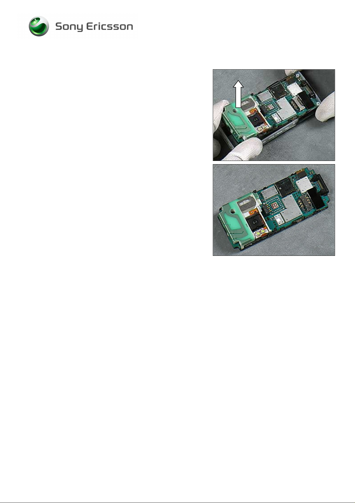
3.20 Main Antenna
REMOVAL
Follow 2.1.1 - 2.1.5 Disassembly instructions!
Insert Front Opening Tool to release the top hook shown in
the picture between the Main Antenna and the Speaker
Box.
Insert Front Opening Tool to release the middle hook shown
in the picture between the Main Antenna and the Speaker
Box.
Insert Front Opening Tool to release the right hook shown
in the picture between the Main Antenna and the Speaker
Box.
Lift up the Main Antenna from the Speaker Box.
1213-5329 2
36(58)
Sony Ericsson Mobile Communications AB
Page 37

Working Instruction, Mechanical
Main Antenna continued
INSTALLATION
Use fingers to position and snap the Main Antenna onto the
Speaker Box.
Follow 4.1.1 - 4.1.7 Reassembly instructions!
1213-5329 2
Sony Ericsson Mobile Communications AB
37(58)
Page 38

Working Instruction, Mechanical
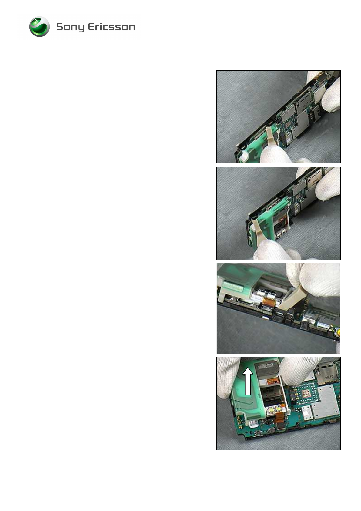
3.21 Keyboard
REMOVAL
Follow 2.1.1 - 2.1.6 Disassembly instructions!
Use Flex Film Assembly Tool to unlatch the Keyfoil
Connector between the Keyboard and the Front Cover.
Use Tweezers to lift out the Front Cover from the Keyboard.
INSTALLATION
Grip the Keyboard using fingers.
Position the Keyboard onto the Front Cover.
1213-5329 2
38(58)
Sony Ericsson Mobile Communications AB
Page 39

Working Instruction, Mechanical
Keyboard continued
Use fingers to snap the Keyfoil Connector between the
Keyboard and the Front Cover.
Follow 4.1.2 - 4.1.7 Reassembly instructions!
1213-5329 2
39(58)
Sony Ericsson Mobile Communications AB
Page 40

Working Instruction, Mechanical
3.22 Receiver
REMOVAL
Follow 2.1.1 - 2.1.6 Disassembly instructions!
Use the Flex Film Assembly Tool to gently press down the
Receiver.
Turn over the Display Assy and use Flex Film Assembly
Tool to lift out the Receiver from the Display Assy.
INSTALLATION
Use the Flex Film Assembly Tool to gently position the
Receiver into the Display Assy.
Follow 4.1.2 - 4.1.7 Reassembly instructions!
Remove the protect film.
1213-5329 2
40(58)
Sony Ericsson Mobile Communications AB
Page 41

Working Instruction, Mechanical
3.23 LCD Gasket
REMOVAL
Follow 2.1.1 - 2.1.6 Disassembly instructions!
Use Tweezers to remove the LCD Gasket.
INSTALLATION
Use Flex Film Assembly Tool to position the LCD Gasket.
Follow 4.1.2 - 4.1.7 Reassembly instructions!
1213-5329 2
41(58)
Sony Ericsson Mobile Communications AB
Page 42

Working Instruction, Mechanical
3.24 Sony Ericsson Icon
REMOVAL
Prepare to remove the Sony Ericsson Icon.
Use Dentist Hook to remove the Sony Ericsson Icon.
INSTALLATION
CLEAN ADHESIVES ON SURFACE WITH ISOPROPYL ALCOHOL IF
NECESSARY!
Use Flex Film Assembly Tool to position the Sony Ericsson
Icon into place.
1213-5329 2
42(58)
Sony Ericsson Mobile Communications AB
Page 43

Working Instruction, Mechanical
3.25 3.2 MP AF Camera
REMOVAL
Follow 2.1.1 - 2.1.6 Disassembly instructions!
Overview picture.
Use camera removal tool and lower into position.
Insert into camera socket and lift upwards as shown in
picture.
INSTALLATION
a. Camera alignment pin.
b. Socket alignment slot.
1213-5329 2
43(58)
Sony Ericsson Mobile Communications AB
Page 44

Working Instruction, Mechanical
3.2 MP AF Camera continued
Use flat tweezers to position camera.
Use fingers to secure at all corners.
DO NOT TOUCH THE LENS!
Look like this.
Follow the 4.1.1 – 4.1.6 Reassembly instructions!
1213-5329 2
44(58)
Sony Ericsson Mobile Communications AB
Page 45

Working Instruction, Mechanical
3.26 Speaker Box Gasket
REMOVAL
Follow 2.1.1 - 2.1.5 Disassembly instructions!
THE ANTENNA FRAME MUST BE ATTACHED ON THE SPEAKER
BOX WHEN REMOVING THE GASKET; THE ANTENNA FRAME IS
FOR PROTECT THE SPEAKERBOX NOT BE DAMAGED BY THE
STRONG ADHESIVE!
Use Tweezers to remove the Speaker Box Gasket start
from the point shown by the arrow in picture.
INSTALLATION
THE ANTENNA FRAME MUST BE ATTACHED ON THE SPEAKER
BOX WHEN INSTALLING THE GASKET; THE ANTENNA FRAME IS
FOR POSITIONING THE GASKET AS THE RED LINES SHOWING IN
PICTURE!
CLEAN ADHESIVES ON SURFACE WITH ISOPROPYL ALCOHOL IF
NECESSARY!
Use Flex Film Assembly Tool to position the Speaker Box
Gasket.
Remove the Protect Film using Flex Film Assembly Tool.
Follow 4.1.1 - 4.1.7 Reassembly instructions!
1213-5329 2
45(58)
Sony Ericsson Mobile Communications AB
Page 46

Working Instruction, Mechanical
3.27 Receiver Gasket
REMOVAL
Follow 2.1.1 - 2.1.6 Disassembly instructions!
Use Tweezers to remove the Receiver Gasket.
CLEAN ADHESIVES ON SURFACE WITH ISOPROPYL ALCOHOL IF
NECESSARY!
INSTALLATION
Use Flex Film Assembly Tool to position the Receiver Box
Gasket and gently remove the Protect Film.
Follow 4.1.2 - 4.1.7 Reassembly instructions!
1213-5329 2
46(58)
Sony Ericsson Mobile Communications AB
Page 47

Working Instruction, Mechanical
3.28 Liquid Intrusion Indicator
INSPECTION
There is one Liquid Intrusion Indicator located on the PCBA.
To get access and inspect the indicator:
Follow 2.1.1 - 2.1.6 Disassembly instructions!
REMOVAL
Remove the activated Liquid Intrusion Indicator with Dentist
Hook and Tweezers.
INSTALLATION
Attach a new Liquid Intrusion Indicator with Tweezers and
Dentist Hook.
Follow 4.1.2 - 4.1.7 Reassembly instructions!
1213-5329 2
47(58)
Sony Ericsson Mobile Communications AB
Page 48

Working Instruction, Mechanical
3.29 Label
Follow 2.1.1 Disassembly instructions!
Read the old label and/or write the information into the
“Label make” program before removal
Note the position of the label before removal
Heat up the label by using hot air, if needed.
Carefully remove the label without causing scratches
If there still are residues, clean the surface with isopropyl
alcohol
Check that the proper label format is loaded in the Zebra
printer.
Write a new label by using the program “Label make” and
check that the printing is OK.
Take the new label and place it into the frame as in the
adjacent picture.
ONE LABEL ONLY IS ALLOWED!
Follow 4.1.7 Reassembly instructions!
1213-5329 2
Company Internal
Sony Ericsson Mobile Communications AB
48(58)
Page 49

Start
Done
Working Instruction, Mechanical
4 Reassembly
After replacing a part listed in Replacements, the instruction of that section usually ends by directing
you to this Reassembly section with a specification of the instructions you have to carry out in order to
reassemble the phone.
REPLACEMENTS
Contents
page
DISASSEMBLY
4.1 Overview
The reassembly is done in the following sequence:
1. LCD Frame Assy (a) PCBA (b)
2. Speaker Box & Antenna
3. Front Cover Assy
4. M2 Cover
5. Frame Assy
6. Screw Cover Assy
7. Battery Cover (a) Battery (b)
REASSEMBLY
m
1213-5329 2
Sony Ericsson Mobile Communications AB
49(58)
Page 50

Working Instruction, Mechanical
4.1.1 Speaker Box Assy & PCBA
Position the Speaker Box Assy using fingers.
Snap the Flash FPC Connector using fingers.
Press down and snap the hooks between the Speaker Box
and the PCBA.
1213-5329 2
Company Internal
Sony Ericsson Mobile Communications AB
50(58)
Page 51

Working Instruction, Mechanical
4.1.2 LCD frame Assy & PCBA
Use fingers to position the LCD Frame Assy and attach the
LCD connector between the LCD and the PCBA.
Press down and snap the top hooks.
Press down and snap the bottom hooks.
Use fingers to attach the LCD connector on the PCBA as
shown by the arrow.
1213-5329 2
Sony Ericsson Mobile Communications AB
51(58)
Page 52

Working Instruction, Mechanical
4.1.3 Front Cover Assy
Use fingers to place the Front Cover Assy into the bottom
position firstly.
Use fingers to place and snap the Front Cover Assy into the
top position.
1213-5329 2
52(58)
Sony Ericsson Mobile Communications AB
Page 53

Working Instruction, Mechanical
4.1.4 M2 Cover
Install the M2 Cover using fingers as shown in picture.
Position the M2 Cover into place as shown in picture.
1213-5329 2
53(58)
Sony Ericsson Mobile Communications AB
Page 54

Working Instruction, Mechanical
4.1.5 Frame Assy
Grip the Frame Assy using fingers.
Position the Frame Assy into the Core Unit.
TIGHTEN THE SCREWS ACCORDING TO THE SCREWING
SEQUENCE SHOWN BY THE NUMBERS IN PICTURE!
Use 18 NCM torque pressure to tighten all four Screws with
Torx Bits no. 6.
CHECK IF THE BATTERY O-RING POSITION IS CORRECT BEFORE
CONTINUING!
1213-5329 2
54(58)
Sony Ericsson Mobile Communications AB
Page 55

Working Instruction, Mechanical
4.1.6 Screw Cover Assy
Grip the Screw Cover Assy using fingers.
Position the Screw Cover Assy into the Frame Assy.
Use 8 NCM torque pressure to tighten the two Screws with
Philips Bit.
Close the Camera Lens Cover using fingers.
1213-5329 2
55(58)
Sony Ericsson Mobile Communications AB
Page 56

Working Instruction, Mechanical
4.1.7 Battery & Battery Cover
Use fingers to insert the contact end of the Battery into the
cavity.
Press the Battery down into the cavity.
Place the Battery Cover on the phone at the top position
firstly.
Snap the Battery Cover into place at the bottom position.
1213-5329 2
56(58)
Sony Ericsson Mobile Communications AB
Page 57

Working Instruction, Mechanical
Battery Cover continued
Use Nylon Pointer to turn the Latch clockwise.
Lock the Latch as shown by the arrow in picture.
1213-5329 2
57(58)
Sony Ericsson Mobile Communications AB
Page 58

Working Instruction, Mechanical
5 Revision history
Rev. Date Changes / Comments
1 2008-05-22 1st release
2 2008-6-17 Add adhesive gasket
1213-5329 2
Company Internal
Sony Ericsson Mobile Communications AB
58(58)
 Loading...