

Page 1
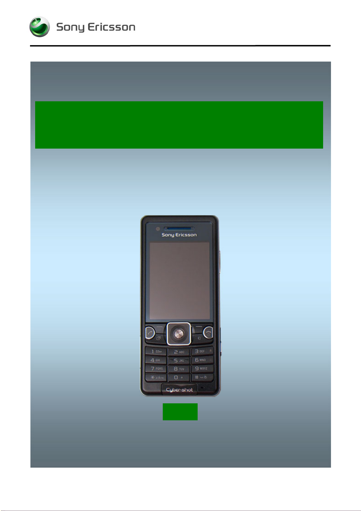
Component Replacement
- electrical -
C510
1223-6749 Rev 7
© Sony Ericsson Mobile Communications AB – Company Internal
Page 2
Component Replacement Repair Drawing Additional Soldering Process/
CONTENTS
1 Replaceable Components ............................................................. 3
2 Component Placing ........................................................................ 6
3 Repair Actions ................................................................................ 7
3.1 Shield Can Fence Modifications .......................................................... 7
3.2 Additional Repair Info ........................................................................... 8
4 Revision History ........................................................................... 10
For general information about electrical repair related issues, refer to
1220-1336: Generic Repair Manual - electrical
1223-6749 Rev 7
© Sony Ericsson Mobile Communications AB – Company Internal
2(2)
Page 3

Component Replacement Repair Drawing Additional Soldering Process/
1 Replaceable Components
EXPLANATION OF ABBREVIATIONS USED IN THE COLUMN ‘COMMENTS’ BELOW
COMPONENT LOCATION
P = Primary Side
S = Secondary Side
MOISTURE SENSITIVITY LEVEL
MSLX (X = 1, 2, 2A, 3, 4, 5, 5A or 6)
For more information on moisture sensitivity levels:
Refer to 1220-1336: Generic Repair Manual – electrical, section ‘Moisture & Baking’!
REPAIR METHOD
HA = Hot Air (removal & mounting)
ST = Soldering Tool (removal & mounting)
HA/ST = Hot Air for removal - Soldering Tool for mounting
BGA = BGA Station
BH = Bottom Heater
ADDITIONAL INFORMATION
Ö1 (2,3,4, etc.) = Proceed to ‘Additional Repair Info’ for further instructions in the indicated section(s).
CALIBRATION
C = Calibration of the phone is required after replacing the component
Calibration to be done by authorized centers only!
1223-6749 Rev 7
© Sony Ericsson Mobile Communications AB – Company Internal
3(3)
Page 4

Component Replacement Repair Drawing Additional Soldering Process/
Position Component Part no. Comments
B4300
B2100
C3149
C3150
C4108
C2227
D2402
D2404
EH3 Shield Can
L1220
L2200
L2201
L2401
L2402
L2403
L2404
L2406
L3115
L3103
L3104
L2410
L2405
L2407
L4201
L4102
N1220
N1220
N1221
N1240
N1400
N2202
N2260
N2402
N2403
N2501
N2502
N2503
N3100
N3101
N4103
N4200
S2401
S2402
IC
Crystal 32768Hz and -20ppm 12.5pF
Capacitor 33.0 mF 3.3 V
Capacitor 33.0 mF 3.3 V
Capacitor
Capacitor
ASIC BB Elina
IC IF ISP1508 ES3 (3.5*3.5*0.8) USB Tran
For Shield Can Lids, refer to
1223-6746: C510 Part List - mechanical
Inductor Wirewound
Ind WW 4.7 uH +-20% 3.6X2.8X1.2
120ohm 0603 2A 50mohm Bead
Inductor 0.0 H ±25%
Inductor 0.0 H ±25%
Inductor 0.0 H ±25%
Inductor 0.0 H ±25%
Inductor 0.0 H ±25%
Inductor 0.0 H ±25%
Ind Chip 0.0 mH 060
Ind Chip 0.0 mH 060
Filter 0
EMI FILTER
Filter 220ohm 0603 2A 0.05ohm Bead
22uH 2.6x2.8x1.2 0.33A 0.76ohm
Ind WW 3.3 uH +-20% 3,0x2,8x1,2mm
Tiger1
Tiger 1,2,5
IC Linear
IC
Module Bluetooth + FM WFBGA100
IC Vreg SC70
LDO Regulator 300mA low noise
IC ESD Prot UDFN 6 2x2 mm
ASIC
LDO1.2 V, 200mA, low noice, CS 5
Voltage regulator 2,8V
IC Vreg
IC CS-9
Tjatte3
IC Driver
Trans N-ch FET
Switch side push
Switch side push
1207-9682
RTM501911/1R1A
1200-0311
1200-0311
1217-0459
1201-8772
1201-4120
1200-1694
1212-4663 P HA
1203-0322
1200-0119
REG70605/15
REG70618/20
REG70618/20
REG70618/20
REG70618/20
REG70618/20
REG70618/20
1201-0706
1201-0706
REG70618/15
REG70618/19
REG70605/24
REG7245372/22
1201-5496
1218-1887
1218-1883
1203-5870
RYT109914/1
1200-9840
1200-6420
1204-5903
1200-6309
1204-5837
RYT1137816/3
RYT1137822/1
RYT113997/4
1200-9978
ROP1013074/1
1201-8077
RYN901936/1
RMD10116/9R1A
RMD10116/9R1A
S HA
S MSLX1 HA C
P HA
P HA
P HA
P HA
S BGA Ö4
S BGA Ö4
P HA
P HA
P HA
P HA Ö3
P HA Ö3
P HA Ö3
P HA Ö3
P HA Ö3
P HA
S HA
S HA
P HA Ö3
P HA Ö3
S HA Ö4
P HA
P HA
P BGA Ö1 C
P BGA Ö1 C (C510a)
P BGA
S BGA
S BGA Ö4
S BGA
P BGA
S BGA Ö4
S BGA Ö6
S BGA
S BGA Ö5
S BGA
S BGA
S BGA Ö4
P BGA
P BGA
S HA/ST
S HA/ST
1223-6749 Rev 7
© Sony Ericsson Mobile Communications AB – Company Internal
4(4)
Page 5

Component Replacement Repair Drawing Additional Soldering Process/
Position Component Part no. Comments
V2200
V2202
V2206
V2400
V2401
V2402
V2404
V2405
V3100
V3101
V2420
V2421
V2425
V4100
V4201
V4401
V4209
X1200
X1210
X1401
X2201
X2405
X4202
X4203
X4204
X4205
Z1400
Z2400
Z4200
Z4201
Z4202
Zener diode 24V
Trans P-ch FET
Diode Schottky
Diode Protection 5, V SOD-923
Diode Protection 5, V SOD-923
Diode Schottky 0,28 V
Diode Protection 0.0 V SOD-923
Diode Protection 0.0 V SOD-923
Diode Protection 0.0 V SOD-923
Diode Protection 0.0 V SOD-923
Zener Diode Voltage Regulator 15V 5perce
Zener Diode Voltage Regulator 15V 5perce
Diode Protection 0.7 V SOD-882
Diode, Shottky, Pb Free
Diode Protection 5.0 V SOD-923
Diode Protection 5.0 V SOD-923
Trans Array
RF probe contact 6 Pin
Coax Connector
Connector
Connector
Connector
Connector
Connector
Connector
Connector
Filter
Filter 100, MHz K1210
Filter 400.0 MHz KNA16400 – W5 1608(1.6x
Filter 400.0 MHz KNA16400 – W5 1608(1.6x
Filter 400.0 MHz KNA16400 – W5 1608(1.6x
RKZ223911/1
RYN122910/1
RKZ123905/2
1201-8440
1201-8440
1200-2065
1201-8393
1201-8393
1201-8393
1201-8393
RKZ223905/2
RKZ223905/2
1201-2253
RKZ123913/1
1209-6023
1209-6023
1200-0320
1203-9688
RPT79938
1214-1927
1201-9869
1210-0559
1208-2706
1205-2016
1210-6820
1202-9266
RTN202941/1
1201-6833
REV50146/1
REV50146/1
REV50146/1
P HA
S HA Ö6
P HA
P HA Ö3
P HA Ö3
S HA Ö7
S HA
S HA
S HA
S HA
S HA Ö4
S HA Ö4
P HA
P HA
S HA
S HA
S HA
P HA/ST
P HA/ST Ö3
S HA/ST Ö4
P HA/ST
P BGA Ö2
S HA/ST
P HA/ST
S HA/ST
S HA/ST
S HA
P HA Ö3
S HA
S HA
S HA
1223-6749 Rev 7
© Sony Ericsson Mobile Communications AB – Company Internal
5(5)
Page 6

Component Replacement Repair Drawing Additional Soldering Process/
2 Component Placing
To access the Component Placing document, double-click the icon below.
Applicable for on-screen viewing only – icon not shown on hard-copies.
1223-6749 Rev 7
© Sony Ericsson Mobile Communications AB – Company Internal
6(6)
Page 7

Component Replacement Repair Drawing Additional Soldering Process/
3 Repair Actions
Refer to the Tools Catalogue/Matrix for information about equipment required for PBA repair!
3.1 Shield Can Fence Modifications
Refer to the pictures below of the primary and secondary sides for repairs that require the Shield Can
Fence to be modified:
• the shield can lid has to be removed
• the red symbols show where the frame should be cut to enable rework
• after rework the height of the frame should not be affected
• it should not be visible that rework has been carried out when the lid has been mounted
Side Primary
Side Secondary
1223-6749 Rev 7
© Sony Ericsson Mobile Communications AB – Company Internal
7(7)
Page 8

Component Replacement Repair Drawing Additional Soldering Process/
Repair Actions
3.2 Additional Repair Info
1
N1220
Protect the system connector, coax connector, battery
connector and the antenna connector with capton tape!
2
X2405
Protect the antenna connector with capton tape!
3
X1210,L2401,L2402,L2403,L2404,L2406,L2410,L240
5,V2400,V2401,Z2400
Protect the system connector with capton tape!
4
X1401,N1400,D2404,D2402,N3101,N2402,L2407,V24
20,V2421
Protect the system connector with capton tape!
1223-6749 Rev 7
© Sony Ericsson Mobile Communications AB – Company Internal
8(8)
Page 9

Component Replacement Repair Drawing Additional Soldering Process/
Repair Actions: Additional Repair Info
5
N2502
Protect the switch and BtB connector with capton tape!
6
N2403, V2202
Protect the BtB connector and system connector with
capton tape!
7
V2402
Protect the BtB connector with capton tape!
1223-6749 Rev 7
© Sony Ericsson Mobile Communications AB – Company Internal
9(9)
Page 10

Component Replacement Repair Drawing Additional Soldering Process/
4 Revision History
Rev. Date Changes / Comments
1 2009-02-20 Initial release
2 2009-02-23 Update parts
3 2009-02-24 Add Component Placing document
4 2009-03-12 Add comment for tiger 125
5 2009-07-13 Corrected position with Z4200, Z4201 and Z4202.
6 2009-09-17 Remove SL5 components N2000,D2000 and XD2000
7 2009-08-18 Add calibrating N1220 Tiger module
1223-6749 Rev 7
© Sony Ericsson Mobile Communications AB – Company Internal
10(10)
 Loading...