

Page 1
ZS-SN10
SERVICE MANUAL
Ver. 1.0 2005.04
US and foreign patents licensed from Dolby Laboratories.
SPECIFICATIONS
US Model
Canadian Model
E Model
Australian Model
Model Name Using Similar Mechanism CFD-E95
Optical Pick-up Block Name KSM-213CDP
Optical Pick-up Name KSS-213C
AUDIO POWER SPECIFICATIONS
(US model only)
POWER OUTPUT AND TOTAL HARMONIC
DISTORTION
With 3.2-ohm loads, both channels driven from
150 - 6,300 Hz; rated 1.8 W per channel-minimum
RMS power, with no more than 10 % total
harmonic distortion in AC operation.
Other Specifications
CD player section
System
Compact disc digital audio system
Laser diode properties
Emission duration: Continuous
Laser output: Less than 44.6 µW
(This output is the value measured at a distance of about
200 mm from the objective lens surface on the optical
pick-up block with 7 mm aperture.)
Spindle speed
200 r/min (rpm) to 500 r/min (rpm) (CLV)
Number of channels
2
Frequency response
20 - 20 000 Hz +0/–1 dB
Wow and flutter
Below measurable limit
Radio section
Frequency range
US, CND, MX, TW models:
FM: 87.5 - 108 MHz
AM: 530 - 1710 kHz
SP, KR, AUS models:
FM: 87.5 - 108 MHz
AM: 531 - 1611 kHz (9 kHz step)
530 - 1610 kHz (10 kHz step)
IF
FM: 10.7 MHz
AM: 450 kHz
Antennas
FM: Telescopic antenna
AM: Built-in ferrite bar antenna
General
Speaker
Full range: 10 cm (4 in.) dia., 3.2 Ω, cone type (2)
Input
LINE IN jack (stereo minijack):
Minimum input level 330 mV
Outputs
Headphones jack (stereo minijack):
For 16 - 64 Ω impedance headphones
Power output
2.3 W + 2.3 W (at 3.2 Ω, 10 % harmonic
distortion)
Power requirements
For player:
US, CND, MX, TW models:
120 V AC, 60 Hz
SP, AUS models:
230 V AC, 50 Hz
KR model:
220 V AC, 60 Hz
9 V DC, 6 size D (R20) batteries
For remote control:
3 V DC, 2 size AAA (R03) batteries
Power consumption
16 W
Battery life
For player:
CD playback
Sony R20P: approx. 2 h
Sony alkaline LR20: approx. 8 h
Radio reception
Sony R20P: approx. 10 h
Sony alkaline LR20: approx. 25 h
Dimensions
Approx. 500 × 145 × 230 mm (w/h/d)
3
/4 × 5 3/4 × 9 1/
(19
Mass
Approx. 3.8 kg (8 lb. 6 oz) (incl. batteries)
Supplied accessories
AC power cord (1) (US, CND, MX, TW models)
Mains lead (1) (SP, KR, AUS models)
Remote control (1)
CD-ROM (SonicStage) (1)
SonicStage Installation/Operating Guide (1)
Design and specifications are subject to change without
notice.
• Abbreviation
AUS: Australian model
CND: Canadian model
KR : Korean model
MX : Mexican model
SP : Singapore model
TW : Taiwan model
8
inches) (incl. projecting parts)
9-879-649-01
2005D0578-1
© 2005.04
PERSONAL AUDIO SYSTEM
Sony Corporation
Personal Audio Group
Published by Sony Engineering Corporation
Page 2
ZS-SN10
r
CAUTION
Use of controls or adjustments or performance of procedures
other than those specified herein may result in hazardous radiation
exposure.
Notes on chip component replacement
• Never reuse a disconnected chip component.
• Notice that the minus side of a tantalum capacitor may be
damaged by heat.
Flexible Circuit Board Repairing
• Keep the temperature of the soldering iron around 270 ˚C
during repairing.
• Do not touch the soldering iron on the same conductor of the
circuit board (within 3 times).
• Be careful not to apply force on the conductor when soldering
or unsoldering.
SAFETY CHECK-OUT
After correcting the original service problem, perform the following
safety check before releasing the set to the customer:
Check the antenna terminals, metal trim, “metallized” knobs, screws,
and all other exposed metal parts for AC leakage.
Check leakage as described below.
TABLE OF CONTENTS
1. SERVICING NOTES ................................................ 3
2. GENERAL ................................................................... 4
3. DISASSEMBLY
3-1. Disassembly Flow ........................................................... 6
3-2. Cabinet Top Assy............................................................. 6
3-3. MAIN Board.................................................................... 7
3-4. Cabinet Front Assy .......................................................... 7
3-5. LCD Board ...................................................................... 8
3-6. CD Block Assy ................................................................ 8
3-7. Optical Pick-up (KSS-213C)........................................... 9
3-8. CD Lid............................................................................. 9
4. ELECTRICAL ADJUSTMENTS .......................... 10
5. DIAGRAMS
5-1. Block Diagram – CD Servo Section –............................ 12
5-2. Block Diagram – TUNER Section – .............................. 13
5-3. Block Diagram – MAIN Section –................................ 14
5-4. Printed Wiring Board – CD Board – .............................. 16
5-5. Schematic Diagram – CD Board –................................. 17
5-6. Printed Wiring Board – TUNER Board –....................... 18
5-7. Schematic Diagram – TUNER Board – ......................... 19
5-8. Printed Wiring Boards – MAIN Section – ..................... 20
5-9. Printed Wiring Boards – POWER Section – .................. 21
5-10. Schematic Diagram – MAIN Section (1/2) – ................. 22
5-11. Schematic Diagram – MAIN Section (2/2) – ................. 23
5-12. Printed Wiring Boards – PANEL Section –.................... 24
5-13. Schematic Diagram – PANEL Section –........................ 25
LEAKAGE TEST
The AC leakage from any exposed metal part to earth ground and
from all exposed metal parts to any exposed metal part having a
return to chassis, must not exceed 0.5 mA (500 microamperes.).
Leakage current can be measured by any one of three methods.
1. A commercial leakage tester, such as the Simpson 229 or RCA
WT -540A. Follow the manufactur ers’ instructions to use these
instruments.
2. A battery-operated A C milliammeter . The Data Precision 245
digital multimeter is suitable for this job.
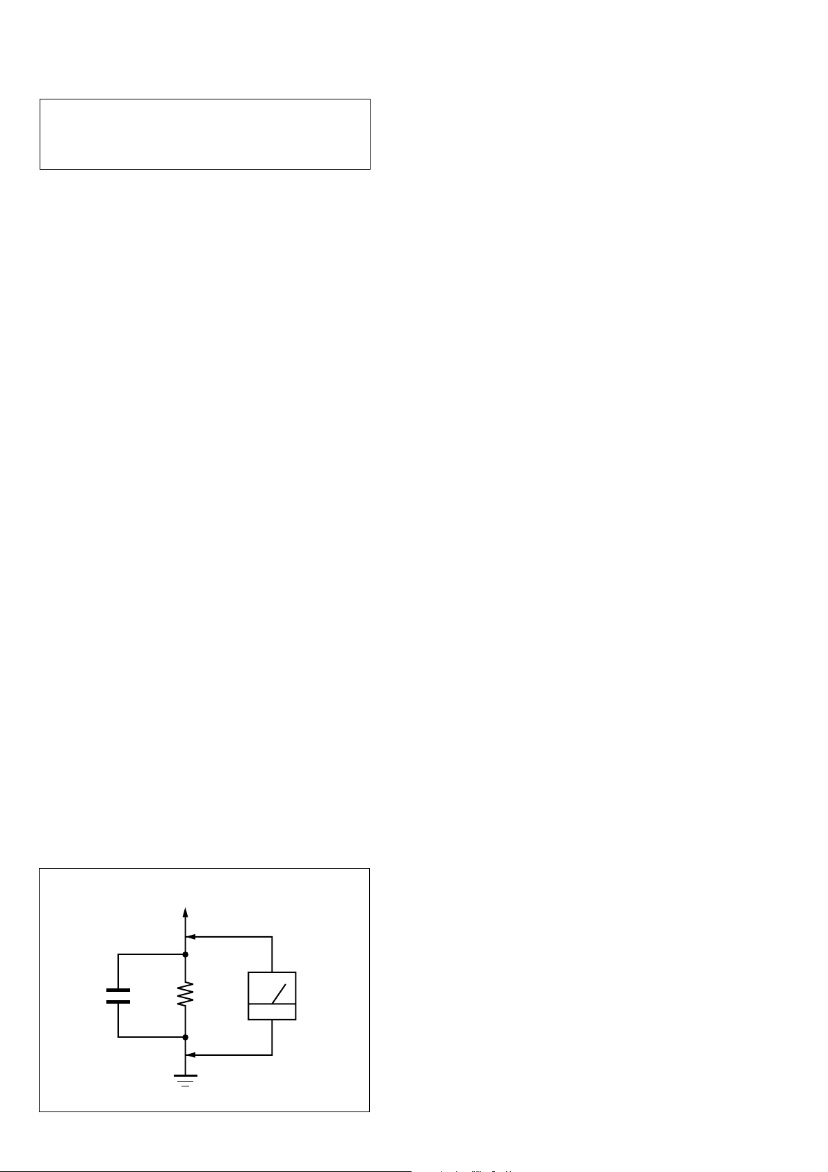
3. Measuring the voltage drop across a resistor by means of a
VOM or battery-operated AC v oltmeter. The “limit” indication
is 0.75 V, so analog meters must have an accurate low-v oltage
scale. The Simpson 250 and Sanwa SH-63Trd are examples
of a passive VOM that is suitable. Nearly all battery operated
digital multimeters that have a 2 V AC range are suitable. (See
Fig. A)
To Exposed Metal
Parts on Set
AC
0.15 µF
1.5 k
Ω
Earth Ground
voltmete
(0.75 V)
Fig. A. Using an AC voltmeter to check AC leakage.
6. EXPLODED VIEWS
6-1. Cabinet Section................................................................ 33
6-2. Cabinet Front Section...................................................... 34
6-3. Cabinet Top Section-1 ..................................................... 35
6-4. Cabinet Top Section-2 ..................................................... 36
6-5. Cabinet Bottom Section................................................... 37
6-6. Optical Pick-up Section (KSM-213CDP) ....................... 38
7. ELECTRICAL PARTS LIST .................................. 39
SAFETY-RELATED COMPONENT WARNING!!
COMPONENTS IDENTIFIED BY MARK 0 OR DOTTED LINE
WITH MARK 0 ON THE SCHEMATIC DIAGRAMS AND IN
THE PARTS LIST ARE CRITICAL TO SAFE OPERATION.
REPLACE THESE COMPONENTS WITH SONY PARTS WHOSE
PART NUMBERS APPEAR AS SHOWN IN THIS MANUAL OR
IN SUPPLEMENTS PUBLISHED BY SONY.
ATTENTION AU COMPOSANT AYANT RAPPORT
À LA SÉCURITÉ!
LES COMPOSANTS IDENTIFIÉS P AR UNE MARQ UE 0 SUR
LES DIAGRAMMES SCHÉMATIQUES ET LA LISTE DES
PIÈCES SONT CRITIQUES POUR LA SÉCURITÉ DE
FONCTIONNEMENT. NE REMPLACER CES COM- POSANTS
QUE PAR DES PIÈCES SONY DONT LES NUMÉROS SONT
DONNÉS DANS CE MANUEL OU D ANS LES SUPPLÉMENTS
PUBLIÉS PAR SONY.
2
Page 3
SECTION 1
SERVICING NOTES
ZS-SN10
NOTES ON HANDLING THE OPTICAL PICK-UP
BLOCK OR BASE UNIT
The laser diode in the optical pick-up block may suffer electrostatic
break-down because of the potential difference generated by the
charged electrostatic load, etc. on clothing and the human body.
During repair, pay attention to electrostatic break-down and also
use the procedure in the printed matter which is included in the
repair parts.
The flexible board is easily damaged and should be handled with
care.
NOTES ON LASER DIODE EMISSION CHECK
The laser beam on this model is concentrated so as to be focused on
the disc reflective surface by the objective lens in the optical pickup block. Therefore, when checking the laser diode emission,
observe from more than 30 cm away from the objective lens.
UNLEADED SOLDER
Boards requiring use of unleaded solder are printed with the leadfree mark (LF) indicating the solder contains no lead.
(Caution: Some printed circuit boards may not come printed with
the lead free mark due to their particular size)
: LEAD FREE MARK
Unleaded solder has the following characteristics.
• Unleaded solder melts at a temperature about 40 °C higher
than ordinary solder.
Ordinary soldering irons can be used but the iron tip has to be
applied to the solder joint for a slightly longer time.
Soldering irons using a temperature regulator should be set to
about 350 °C.
Caution: The printed pattern (copper foil) may peel away if
the heated tip is applied for too long, so be careful!
• Strong viscosity
Unleaded solder is more viscou-s (sticky, less prone to flow)
than ordinary solder so use caution not to let solder bridges
occur such as on IC pins, etc.
• Usable with ordinary solder
It is best to use only unleaded solder but unleaded solder may
also be added to ordinary solder.
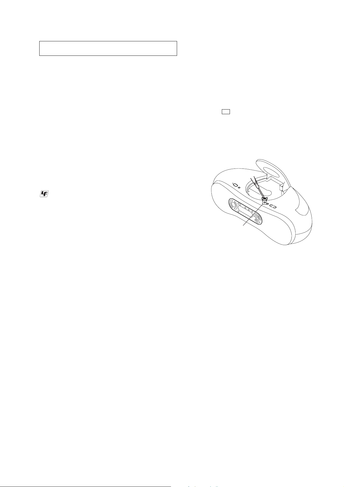
LASER DIODE AND FOCUS SEARCH OPERATION
CHECK
During normal operation of the equipment, emission of the laser
diode is prohibited unless the upper lid is closed while turning ON
the S801. (push switch type)
The following checking method for the laser diode is operable.
• Method
Emission of the laser diode is visually checked.
1. Open the upper lid.
2. Push the S801 as shown in Fig.1.
Note: Do not push the detection lever strongly , or it may be bent or damaged.
3. Press the u button.
4. Check the object lens for confirming normal emission of the
laser diode. If not emitting, there is a trouble in the automatic
power control circuit or the optical pick-up.
In this operation, the object lens will move up and down 2
times along with inward motion for the focus search.
S801
Fig.1 Method to push the S801
3
Page 4
ZS-SN10
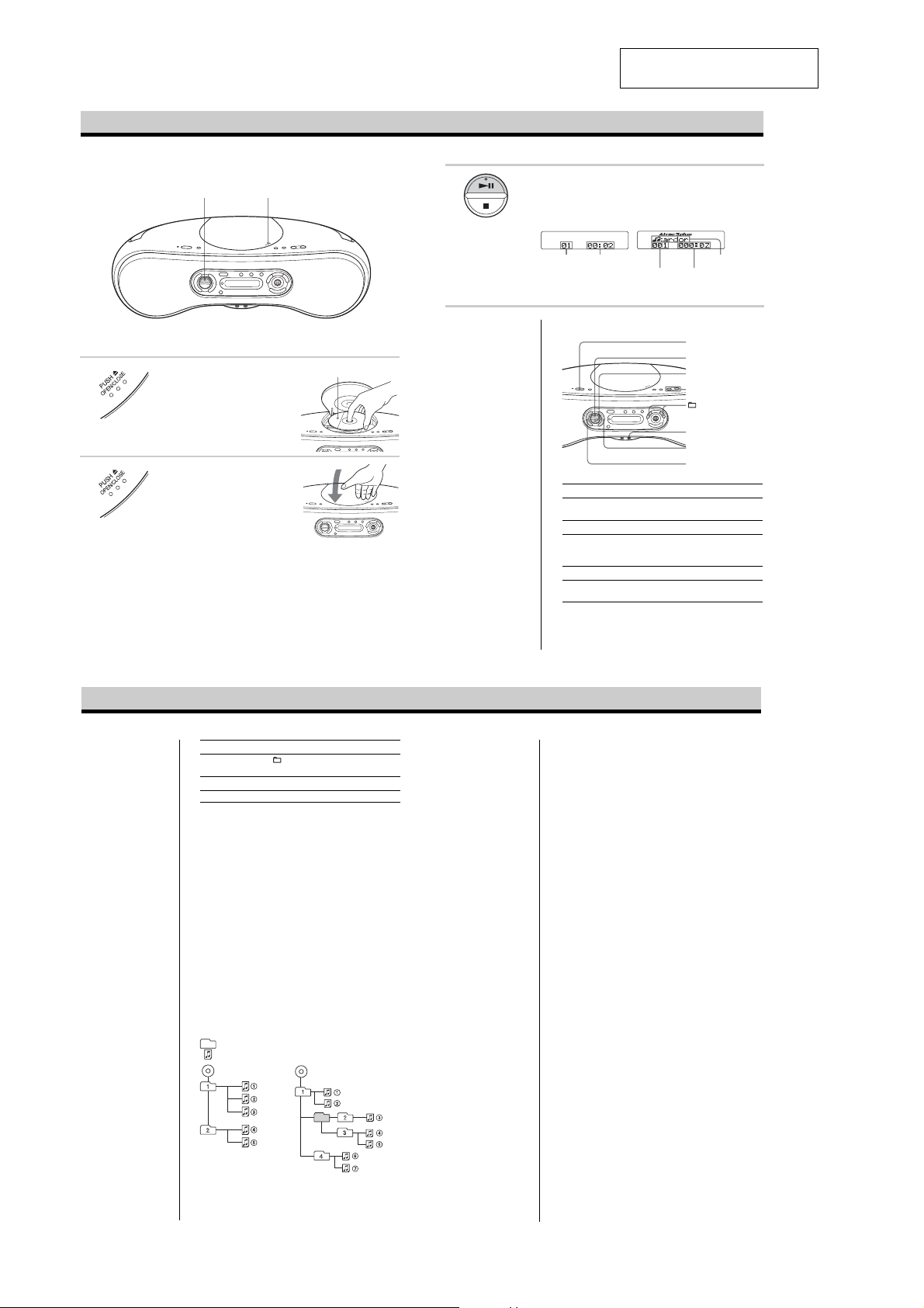
Basic Operations
Playing a CD
SECTION 2
GENERAL
3
1, 2
3 Press u (N on the remote) (direct
power-on).
The player plays all the tracks once.
Display
Audio CD
This section is extracted from
instruction manual.
ATRAC CD/MP3 CD*
Connect the supplied AC power cord.
1 Press PUSH Z OPEN/CLOSE to
2 Press PUSH Z OPEN/CLOSE to
open the CD lid and place the CD on
the CD tray.
close the CD lid.
With the label side up
Note
Before playing an ATRAC
CD/MP3 CD, this player
reads all file and group
information on the CD.
Depending on the file
structure, it may take more
than a minute to read them.
During this time, “Reading”
is displayed.
Tips
•To listen through
headphones, connect the
headphones to the i
(headphones) jack.
•Playback starts from the
track you last stopped
playing (Resume play).
To cancel the resume play
to start play from the
beginning of the first track,
press x in stop mode.
Track number
Playing time
File number
*When playing an MP3 CD, “MP3”
appears in the display.
Use these buttons for additional operations
To Press
adjust the volume VOLUME +*1, – (VOL +*1, – on the
stop playback x
pause playback u*1(X on the remote)
go to the next track >
go back to the .
previous track
*1The button has a tactile dot.
remote)
Press the button again to resume play after
pause.
File name
Playing time
POWER
u
x
VOLUME –, +
–, +
i
>
.
Notes
• If ATRAC3plus files and
MP3 files are recorded on
the same CD, this CD
player plays the
ATRAC3plus first.
• The playback capability of
this CD player may vary
depending on the quality of
the disc and the condition of
the recording device.
• Characters that can be
displayed on this CD player
are listed below.
–A to Z
–a to z
–0 to 9
–! " # $ % & ' ( ) * + , - . / :
; < = > ? @ [ \ ] ^ _ ` { | }
~
If you use other characters
on your computer using
software such as
SonicStage, they are
displayed as “–” on this CD
player.
• On a disc that has
ATRAC3plus/MP3 files, do
not save files in other
formats and do not make
unneccessary groups.
To Press
2
select a group*
remove the CD PUSH Z OPEN/CLOSE*
turn on/off the player POWER
2
This function works for ATRAC CDs/MP3 CDs only.
*
*3Once you open the CD lid, the track to start play will change to
the beginning of the first track.
The structure of ATRAC CDs/MP3 CDs
ATRAC CDs/MP3 CDs consist of “files” and “groups.” A
“file” is equivalent to a “track” of an audio CD. A “group”
is a bundle of files and is equivalent to an “album.”
For MP3 CDs, this CD player recognizes an MP3 folder as
a “group” so that ATRAC CDs and MP3 CDs can be
operated in the same way.
In this manual, we use the word “track” in description of
the operations available for both ATRAC CDs/MP3 CDs
and audio CDs, and the word “file” for the operations
available for ATRAC CDs/MP3 CDs only.
Playing order of ATRAC CDs and MP3 CDs
For ATRAC CDs, files are played in the order selected in
SonicStage.
For MP3 CDs, the playing order may differ depending on
the method used to record MP3 files on the disc. In the
following example, files are played in order of 1 to 7.
Group
File
ATRAC CD
+ to go forward and – to go
backward
MP3 CD
3
Notes on ATRAC CDs
•Maximum number of groups: 255
Maximum number of files: 999
• CD-Rs/CD-RWs recorded in the ATRAC3plus format cannot be
played on your computer.
Notes on MP3 CDs
•Maximum number of groups: 255
Maximum number of files: 511
Maximum directory level: 8
•A group that does not include an MP3 file is skipped.
• Be sure to add the file extension “mp3” to the file name.
However, if you add the file extension “mp3” to a file other than
an MP3 file, the player will not be able to recognize the file
properly.
• This player can play bit rates of 32 to 320 kbps, and sampling
frequencies of 32/44.1/ 48 kHz.
•To compress a source in an MP3 file, we recommend setting the
compression parameters to “44.1 kHz,” “128 kbps,” and
“Constant Bit Rate.”
•To record up to the maximum capacity, set the writing software
to “halting of writing.”
•To record to the maximum capacity at one time up on media that
has nothing recorded on it, set the writing software to “Disc at
Once.”
4
Page 5
ZS-SN10
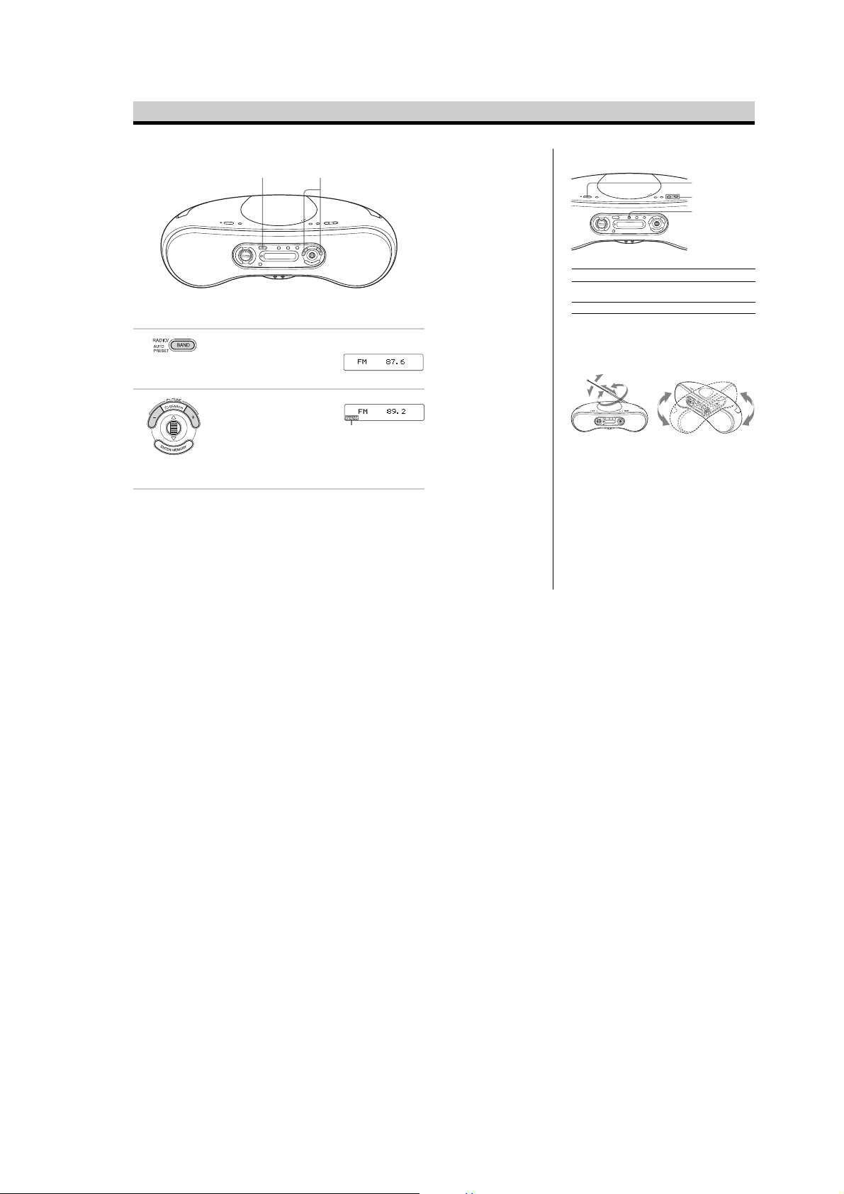
Listening to the radio
1 2
Connect the supplied AC power cord.
1 Press RADIO•BAND•AUTO
2 Hold down TUNE + or – until the
PRESET repeatedly until the band
you want appears in the display
(direct power-on).
frequency digits begin to change in
the display.
The player automatically scans the
radio frequencies and stops when it
finds a clear station.
If you can’t tune in a station, press
TUNE + or – repeatedly to change
the frequency step by step.
Display
Indicates an FM
stereo broadcast
Tip
If the FM broadcast is noisy,
press MODE repeatedly until
“Mono” appears in the
display and radio will play in
monaural.
Use these buttons for additional operations
POWER
VOLUME –, +
MODE
To Press
adjust the volume VOLUME +*, – (VOL +*, – on the
turn on/off the radio POWER
* The button has a tactile dot.
To improve broadcast reception
Reorient the antenna for FM. Reorient the player itself for
AM.
for FM
remote)
for AM
5
Page 6
ZS-SN10
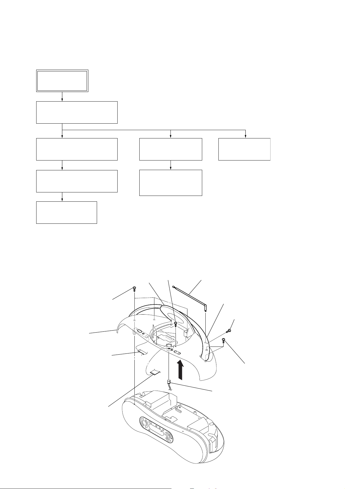
• This set can be disassembled in the order shown below.
3-1. DISASSEMBLY FLOW
SET
3-2. CABINET TOP ASSY
(Page 6)
SECTION 3
DISASSEMBLY
3-3. MAIN BOARD
(Page 7)
3-4. CABINET FRONT ASSY
(Page 7)
3-5. LCD BOARD
(Page 8)
Note: Follow the disassembly procedure in the numerical order given.
3-2. CABINET TOP ASSY
3
Open the CD lid.
7
three screws
(B3)
3-6. CD BLOCK ASSY
(Page 8)
3-7. OPTICAL PICK-UP
(KSS-213C)
(Page 9)
4
three screws
(B3)
3-8. CD LID
(Page 9)
2
telescopic antenna (ANT1)
5
Lift the handle.
1
screw (M3)
qs
cabinet top assy
qa
flexible flat cable (4 core)
(CN403)
6
two screws
(B3)
0
wire (flat type) (23 core)
(CN102)
8
9
connector
6
Page 7
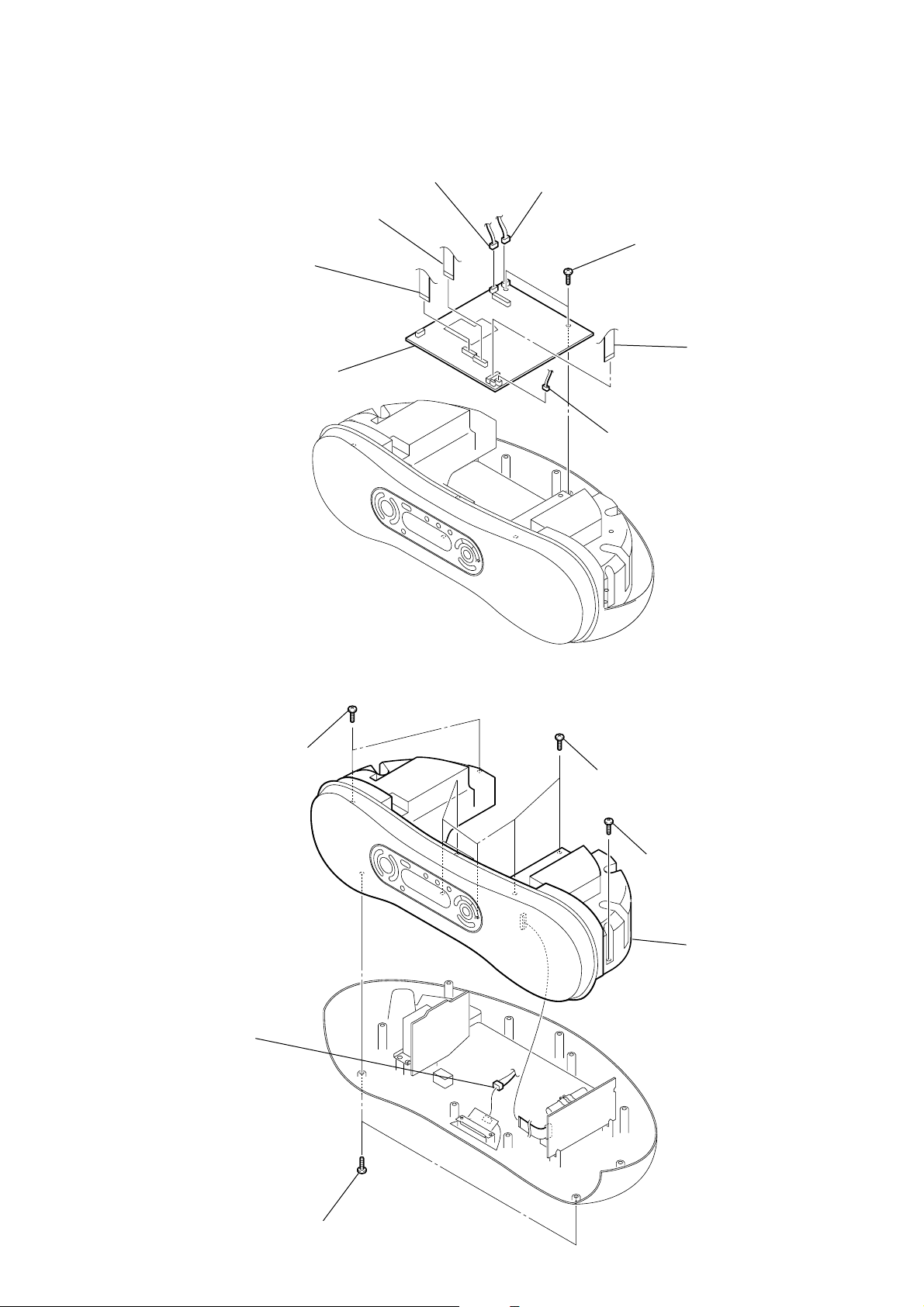
3-3. MAIN BOARD
4
flexible flat cable
(11 core) (CN806)
5
flexible flat cable
(11 core) (CN807)
8
MAIN board
3
connector (CN901)
2
connector (CN301)
1
7
two screws
(B2.6)
6
flexible flat cable
(11 core) (CN801)
connector (CN302)
ZS-SN10
3-4. CABINET FRONT ASSY
3
two screws
(B3)
1
connector
(CN323)
4
five screws
(B3)
5
screw (B3)
6
cabinet front assy
2
two screws
(B3)
7
Page 8
ZS-SN10
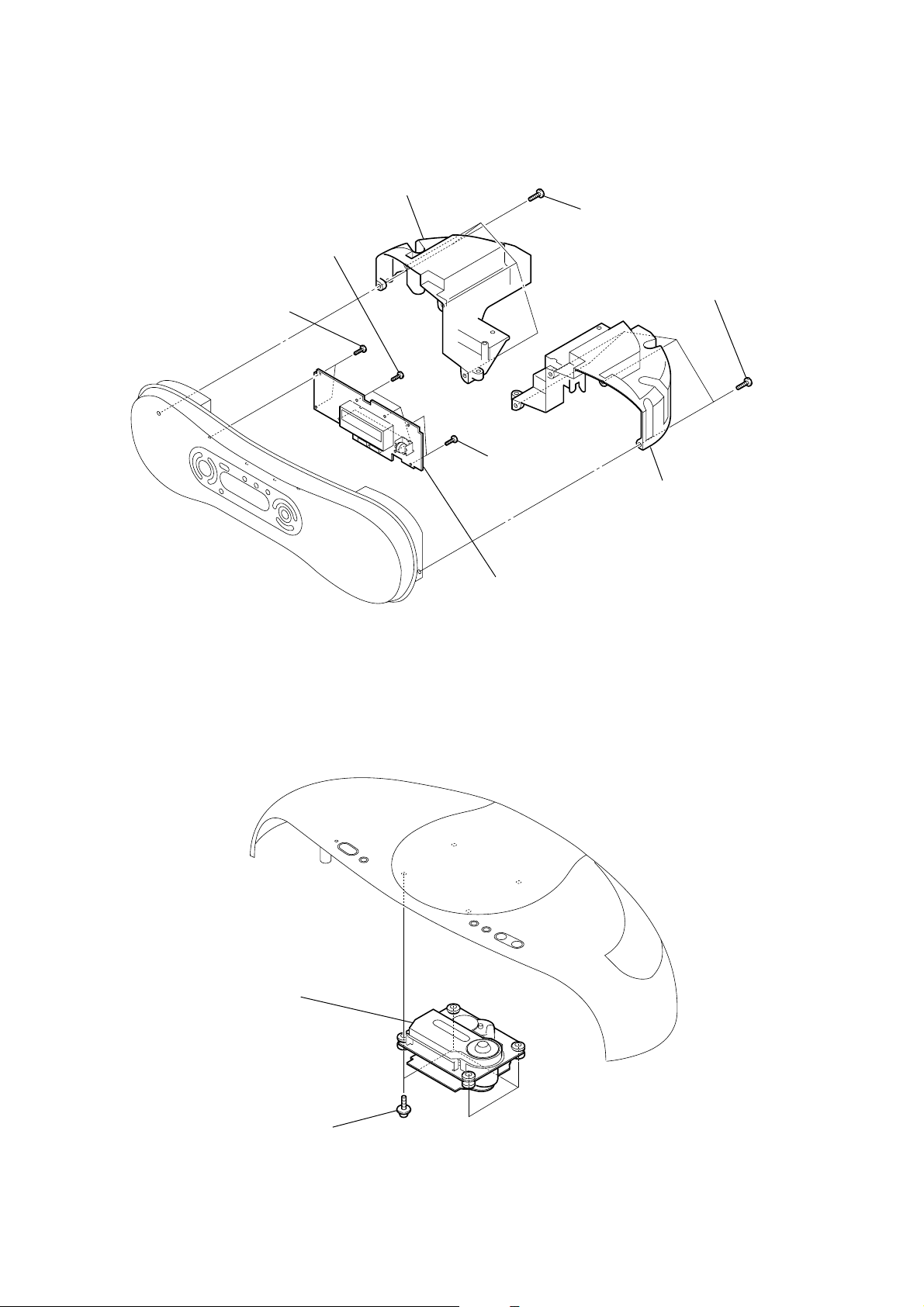
3-5. LCD BOARD
6
two screws
(B2.6)
5
four screws
(B2.6)
2
speaker box (L)
7
two screws
(B2.6)
1
four screws
(B3)
3
four screws
(B3)
4
speaker box (R)
3-6. CD BLOCK ASSY
2
CD block assy
8
LCD board
1
four screws
8
Page 9
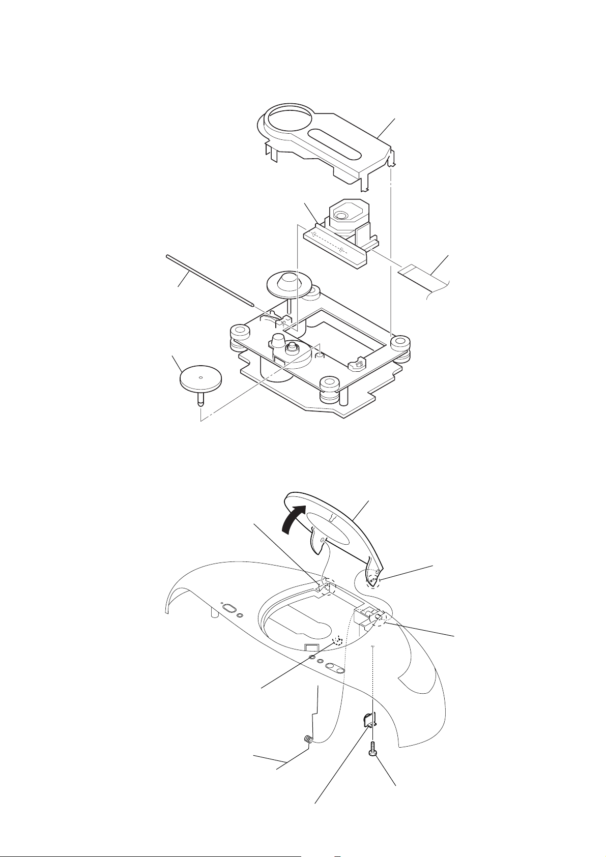
3-7. OPTICAL PICK-UP (KSS-213C)
3
sled shaft
5
optical pick-up
(KSS-213C)
CD cover
1
4
flexible flat cable (16 core)
ZS-SN10
3-8. CD LID
2
gear (A)
7
boss
5
9
CD lid
6
claw
8
boss
2
CD spring
1
claw
4
damper
3
screw (B2.6)
9
Page 10
ZS-SN10
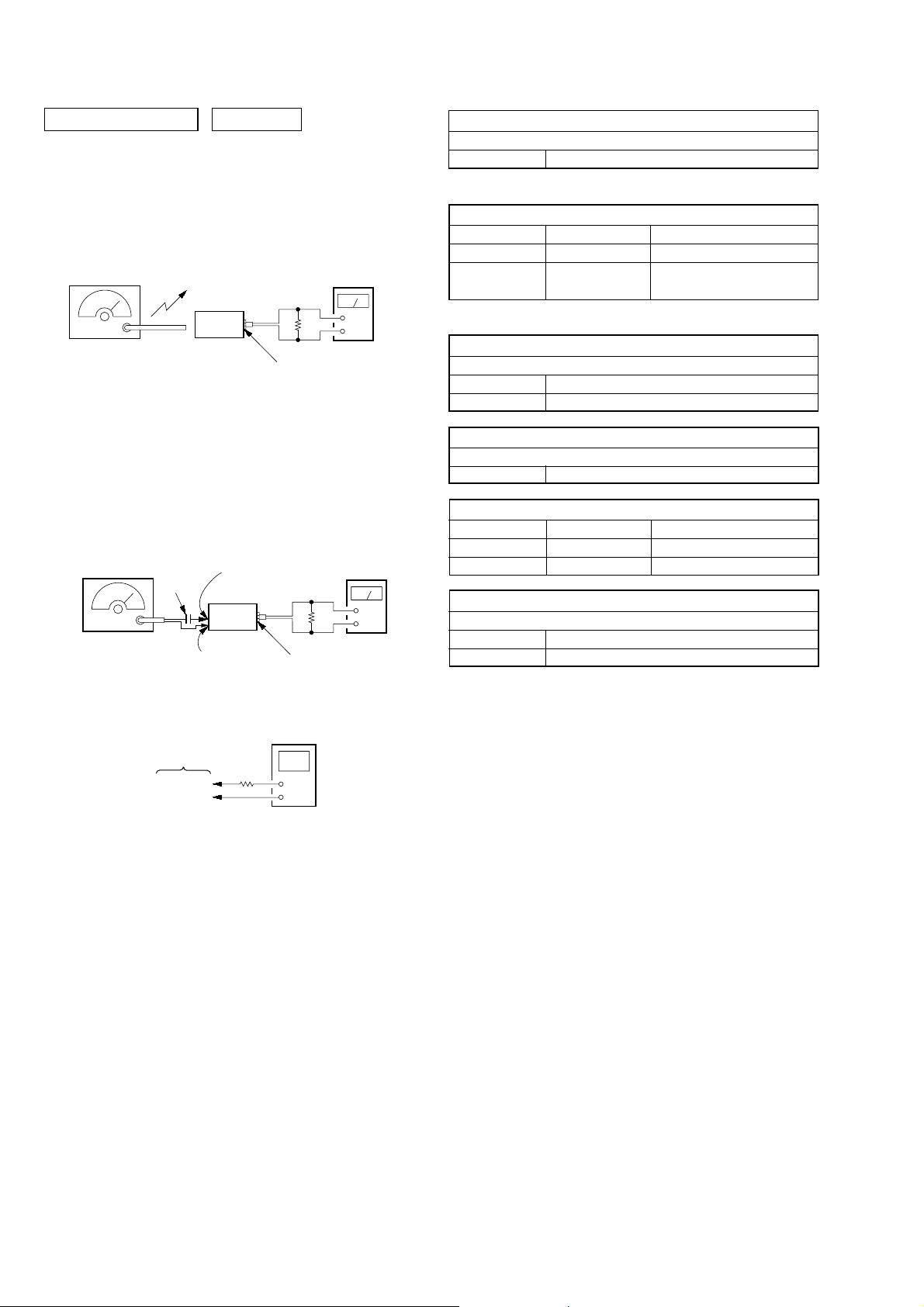
SECTION 4
ELECTRICAL ADJUSTMENTS
TUNER SECTION 0 dB=1 µV
[AM]
Setting:
Function: RADIO
RADIO/BAND, AUTO PRESET button: AM
AM RF signal
generator
30% amplitude
modulation by
400 Hz signal
Output level:
as low as possible
[FM]
Setting:
Function: RADIO
RADIO/BAND, AUTO PRESET button: FM
FM RF signal
generator
75 kHz frequency
deviation by 1 kHz
signal
Output level:
as low as possible
Put the lead-wire
antenna close to
the set.
set
TUNER board
TP (ANT)
0.01 µF
set
TUNER board
TP (GND)
32
i
level meter
Ω
jack (J301)
level meter
32
Ω
i
jack (J301)
AM IF ADJUSTMENT
Adjust for a maximum reading on level meter
T1 450 kHz
(): Singapore, Korean and Australian models
AM FREQUENCY COVERAGE ADJUSTMENT
Adjustment Part Frequency Display Reading on Digital Voltmeter
L4 530 kHz (531 kHz) 1.0 ± 0.05 V
Confirmation
+
–
Adjust for a maximum reading on level meter
L3 620 kHz (621 kHz)
CT3 1,400 kHz (1,404 kHz)
Adjust for a minimum reading on level meter
T2 10.7 MHz
FM FREQUENCY COVERAGE ADJUSTMENT
Adjustment Part Frequency Display Reading on Digital Voltmeter
L2 108 MHz 3.0 ± 0.2 V
Confirmation 87.5 MHz 1.3 ± 0.3 V
+
–
Adjust for a maximum reading on level meter
L1 87.5 MHz
CT1 108 MHz
1,710 kHz
(1,611 kHz)
5.3 ± 0.7 V (5.2 ± 0.6 V)
(): Singapore, Korean and Australian models
AM TRACKING ADJUSTMENT
FM IF ADJUSTMENT
FM TRACKING ADJUSTMENT
Adjustment and Connecting Location: TUNER board
(See page 11)
digital voltmeter
TUNER board
100 k
TP (VT)
TP (GND)
Ω
• Repea t the procedures in each adjustment several times, and
the tracking adjustments should be finally done by the trimmer
capacitors.
• Remove FM antenna in FM adjustment.
10
Page 11
ZS-SN10
VOLT/DIV: 0.2 V (with the 10: 1 probe in use.)
TIME/DIV: 200 ns
0.5 to 1.1 Vp-p
When observing the eye pattern, set the oscilloscope
for AC range and raise vertical sensitivity.
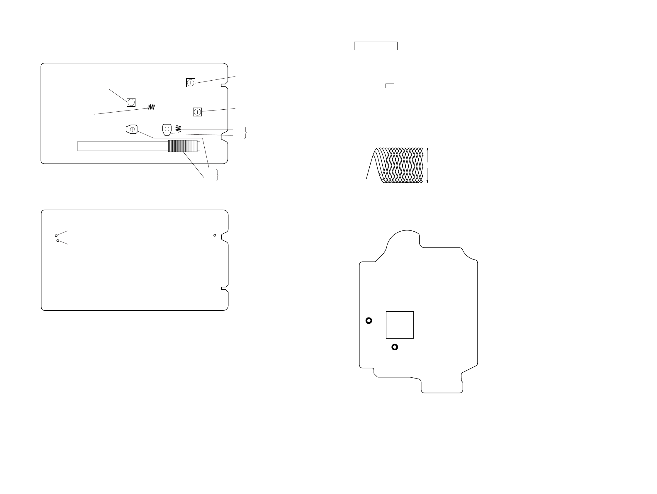
Adjustment and Connecting Location:
– TUNER Board (Component Side) –
L4
AM Frequency Coverage Adjustment
L2
FM Frequency Coverage Adjustment
– TUNER Board (Conductor Side) –
T2 FM IF Adjustment
T1 AM IF Adjustment
L1
CT1
CT3
AM T rac king Adjustment
L3
CD SECTION
FOCUS BIAS CHECK
1. Connect the oscilloscope to TP (RF A CO) and TP (VC) on the
CD board.
2. Insert the disc (PATD-012). (Part No.: 4-225-203-01)
3. Press the u button.
4. Confirm that the oscilloscope waveform is as shown in the
figure below. (eye pattern)
A good eye pattern means that the diamond shape (◊) in the
center of the waveform can be clearly distinguished.
• RF signal reference waveform (eye pattern)
FM T rac king Adjustment
Checking Location:
TP
(VT)
TP
(GND)
TP
(ANT)
– CD Board (Conductor Side) –
TP
(VC)
IC201
TP
(RFACO)
ZS-SN10
1111
Page 12
ZS-SN10
SECTION 5
DIAGRAMS
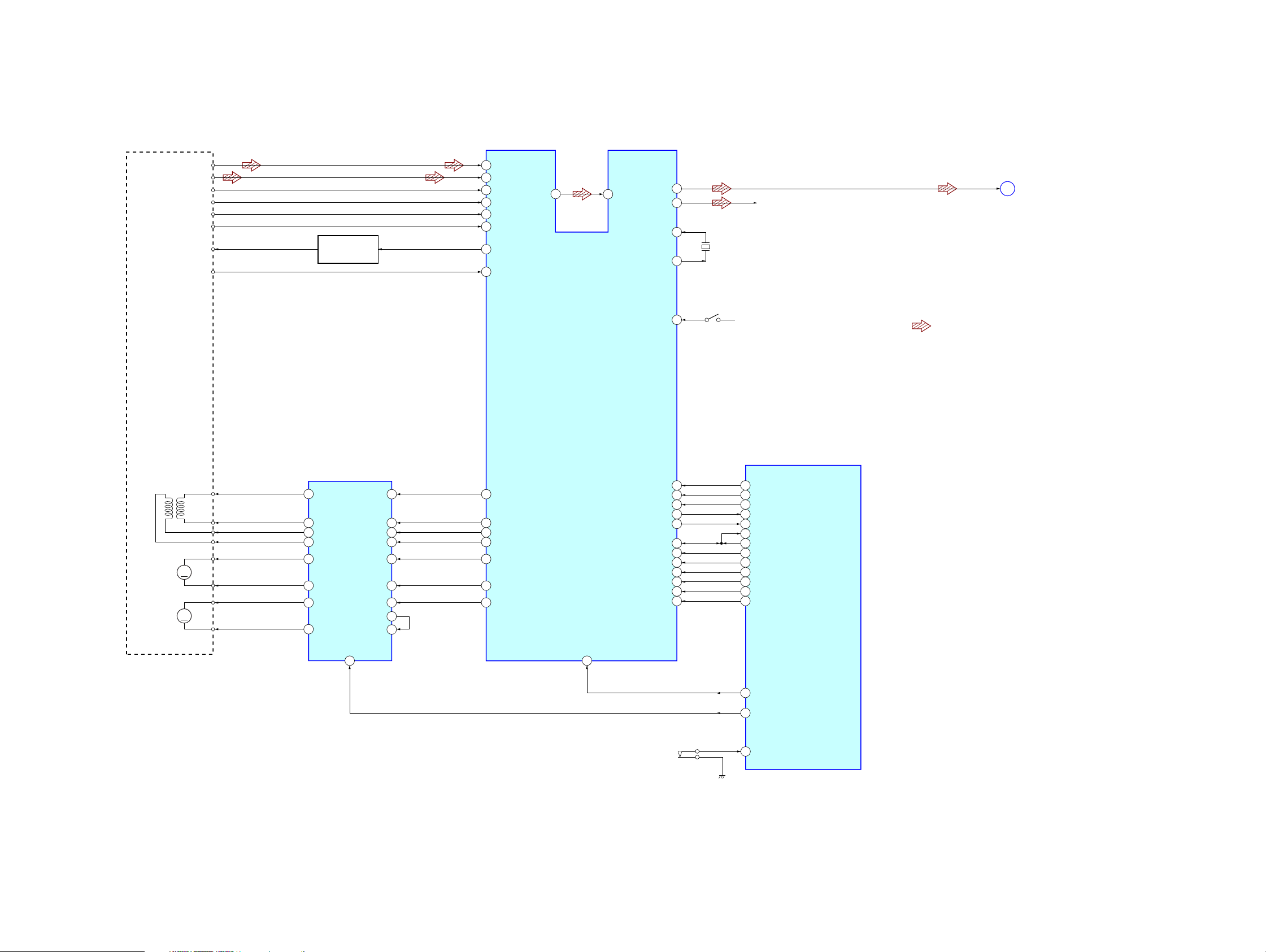
5-1. BLOCK DIAGRAM – CD SERVO SECTION –
OPTICAL
PICK-UP BLOCK
(KSM-213CDP)
A
B
C
D
E
F
LD
PD
AUTOMATIC
POWER CONTROL
Q321
57
A
58
B
59
C
RFACO
60
D
50
E
51
F
66
LD
67
PD
70
71
RFACI
AOUT1
AOUT2
XTAI
XTAO
112
117
109
108
X202
16.9344MHz
R-CH
CD-L
A
(Page 14)
M402
(SLED)
M401
(SPINDLE)
2-AXIS
DEVICE
S201
(LIMIT)
39
SSTP
CD DSP
IC201
FOCUS/TRACKING COIL DRIVER,
SLED/SPINDLE MOTOR DRIVER
FCS+
FCS–
TRK+
TRK–
SL+
M
SL–
SP+
M
SP–
12
11
13
14
17
16
CH2OUTF
CH2OUTR
CH1OUTR
CH1OUTF
CH3OUTF
CH3OUTR18
CH4OUTF
CH4OUTR15
IC402
CH2FIN
CH2RIN
CH1RIN
CH1FIN
CH3FIN
CH3RIN 22
OPIN+
OPOUT
CH4IN
89
6
7
5
4
23
2
27
24
45
FFDR
46
FRDR
44
TRDR
43
TFDR
41
SFDR
42
SRDR
38
MDP
DATA
11
CLOK
16
XLAT
SENS 20
26 SCOR56
SCOR
12
DATA2
90
CLOK2
13
XLAT2
14
REQ
IREQ 10
15
ACK
XTACN
7
CD +3.3V
19
DATA
20
CLOK
XLAT55
18
SENS
IDATA2
58
ODATA259
60
CLOK2
61
XLAT2
REQ62
57
IREQ
63
ACK
XTACN67
SYSTEM CONTROLLER
IC801 (1/2)
• R-ch is omitted due to same as L-ch.
• SIGNAL PATH
: CD PLAY
ZS-SN10
MUTE
20
XRST
8
(CD LID OPEN/CLOSE DETECT)
S801
1212
XRST68
M-MUTE66
53 CD-DOOR
Page 13
5-2. BLOCK DIAGRAM – TUNER SECTION –
ANT1
FM LEAD WIRE
ANTENNA
FM/AM RF AMP, MIX, OSC,
FM/AM IF AMP, DET, MPX
IC1
10
QUAD
T2
FM IFT
ZS-SN10
T2
FM IF
L1
FM RF
CT1, L1
FM TRACKING
L3
AM FERRITE-ROD
ANTENNA
CT3, L3
AM TRACKING
CT1
CT3
D1
D3
(1/2)
FM
RF-IN
2
FM
RF-OUT
24
AM
RF-IN
22
L4
AM FREQUENCY
COVERAGE
L4
AM
OSC
FM
RF AMP
AM
RF AMP
D3
(2/2)
FM
MIX
FM
OSC
AM
MIX
AM
OSC
AM OSC
20 21
FM OSC
BUFFER
BUFFER
MIX-OUT
4 7
T1
AM IFT
T1
AM IF
OSC
-OUT
19
L2
FM FREQUENCY
COVERAGE
L2
FM OSC
D2
CF2
CF4
FM
IF-IN
FM IF
AMP
AM
IF-IN
AM IF
6
AMP
FM
DET
AM
DET
IF
BUFFER
IF-OUT
17 18
AF
BUFFER
LEVEL
DET
DET
-OUT
ST
IND
ST-IND
MPX
-IN
AF
16
15
AMP
MPX
LPF1/BAND
LPF2/MO-ST
13
14
MUTE
STEREO/
MONO,
FM/AM
L-OUT
R-OUT
12
11
R-CH
TU-L
B
(Page 14)
• R-ch is omitted due to same as L-ch.
• SIGNAL PATH
: FM
: AM
X1
75kHz
VT B+
LOW-PASS
FILTER
6
PD
LP-OUT
MW/LW
XOUT
20
19
XIN
REFERENCE
DIVIDER
FM/AM PLL
IC2
LOW-PASS
FILTER
UNLOCK
DETECT
LP-IN
PHASE
DETECTOR/
CHARGE PUMP
12 BIT
PROGRAMMABLE
DIVIDER
SWALLOW
COUNTER
111218
FM IN
AM IN
1/2
SHIFT REGISTER & LATCH
10 9
IF IN
UNIVERSAL
COUNTER
ST-IND
BAND
7
BAND
13817 16
MO/ST
CCB
INTERFACE
DI
2
CL
3
CE
1
DO
4
MUTING
Q808
R MUTING
R DATA
R CLOCK
R CE
R COUNT
R DATA, R CLOCK, R CE,
R COUNT, R MUTING
C
(Page 14)
ZS-SN10
1313
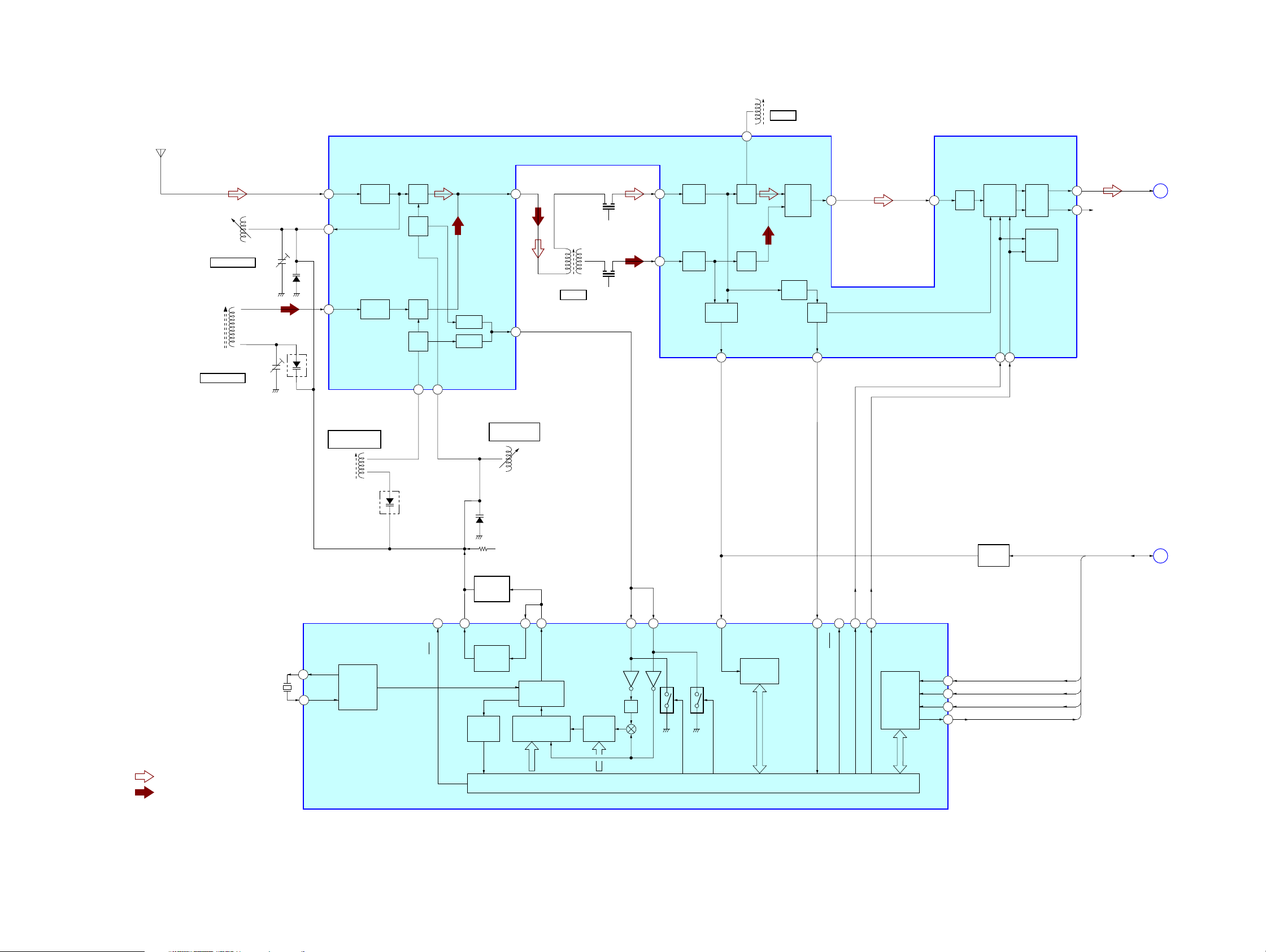
Page 14

ZS-SN10
5-3. BLOCK DIAGRAM – MAIN SECTION –
C
(Page 13)
(Page 12)
(Page 13)
R DATA, R CLOCK,
R CE, R COUNT,
R MUTING
A
B
R DATA
R CLOCK
R CE
R COUNT
R MUTING
CD-L
TU-L
28
29
30
27
31
J322
LINE IN
R-DATA
R-CLOCK
R-CE
R-COUNT
R-MUTE
X1
83 82
R-CH
• R-ch is omitted due to same as L-ch.
• SIGNAL PATH
: FM
6
CD-L
95
LCD-E
94
LCH
LCD-RES
LCD-RW
93
16
MEGA BASS
CONTROL
D301
Q101
15
MEGABASS
R-CH
MUTING
Q121
21
A-MUTE
R-CH
CD +2.5V
4
SEL L
8
RA-L
R-CH
SYSTEM CONTROLLER
IC801 (2/2)
78
SHIFT
X1A
79 80
X0
X0A
10
100
LI-L
14 13
9
BL
SI
SC
10
VOL-CLK
VOL-DATA
LCD-DB0 – LCD-DB7
85 – 92
1
R-IN
INPUT SELECT,
ELECTRICAL VOLUME,
SURROUND/TONE CONTROL
IC301
LCD-RS
96
3.3V-CHECK
BUCKUP-ON
CD3.3V-ON
POWER
AMP
IC304
REGULATOR
43
26
25
+2.5V
IC202
CD +3.3V CD +6V
DC/DC
CONVERTER
IC901, Q956
B+ SWITCH
Q813
RE B+
SYS +3.3V
B+ SWITCH
Q804, 806
REGULATOR
RMC +5V
+6V
Q954
D401
OPR/
BATT
SP101
(L-CH)
SP201
(R-CH)
SYS +3.3V
J301
i
D801
SW +9V
B+ SWITCH
Q951 – 953
: CD PLAY
AMP B+
RECT
D901 – 904
F902
T901
POWER
TRANSFORMER
J901
AC IN
DRY BATTERY
SIZE "D"
(IEC DESIGNATION R20)
6PCS. 9V
Q802
X801
4.19MHz
Q801, 802
SHIFT CLOCK
Q801
X802
32.768kHz
LED DRIVE
Q803
D402
(LCD BACK LIGHT)
LIQUID CRYSTAL DISPLAY
LCD401
REMOTE CONTROL
EEPROM
IC804
(JOG)
SYS +3.3V
S402 – 407
S410 – 414, 425
S418 – 424
RECEIVER
IC401
ROTARY
ENCODER
WAKE UP
SWITCH
SDA
SCL
S401
Q807
22
P-CON
45
VH
64 REMOTE
5
6
EEP-SDA
8
EEP-SCL
7
98 JOG-A
99 JOG-B
52 WP
41 KEY0
39 KEY1
40 KEY2
VOL-CHECK
VH-CONT
VM
VM-CONT
69
70LOAD
46
32
44
24TU-ON
77RESET
54AC-IN
DC LEVEL
DETECT
Q821, 822
DC LEVEL
DETECT
Q811, 812
AC CHECK
Q805
E.VOL B+
RADIO +6V
LOAD CONTROL
SWITCH
Q823, 824
B+ SWITCH
Q809, 810
RESET SIGNAL
GENERATOR
IC803
AU +6V
SYS +3.3V
+6V
REGULATOR
Q955
+3.3V
REGULATOR
IC802
ZS-SN10
1414
Page 15

ZS-SN10
• Note for Printed Wiring Boards and Schematic Diagrams
Note on Printed Wiring Board:
• X : parts extracted from the component side.
• Y : parts extracted from the conductor side.
• W : indicates side identified with part number.
f
•
• : Pattern from the side which enables seeing.
Caution:
Pattern face side: Parts on the pattern face side seen from
(Conductor Side) the pattern face are indicated.
Parts face side: Parts on the parts face side seen from
(Component Side) the parts face are indicated.
: internal component.
(The other layers' patterns are not indicated.)
Note on Schematic Diagram:
• All capacitors are in µF unless otherwise noted. (p: pF)
50 WV or less are not indicated except for electrolytics
and tantalums.
• All resistors are in Ω and 1/
specified.
• f : internal component.
• C : panel designation.
Note:
The components identified by mark 0 or dotted line with mark 0 are
critical for safety.
Replace only with part
number specified.
• A : B+ Line.
• H : adjustment for repair.
• Power voltage is dc 4.5V and fed with regulated dc power
supply from pin 1 and 2 of CN902 on the BATTERY 1
board, and from pin 3 and 2 as well.
no mark : FM
〈〈 〉〉 : AM
(): CD PLAY
• Voltages are tak en with a V OM (Input impedance 10 MΩ).
Voltage v ariations may be noted due to normal production
tolerances.
• Waveforms are taken with a oscilloscope.
Voltage v ariations may be noted due to normal production
tolerances.
• Circled numbers refer to waveforms.
• Signal path.
F : FM
f : AM
J : CD PLAY
j : LINE IN
• Abbreviation
AUS: Australian model
CND : Canadian model
KR : Korean model
MX : Mexican model
SP : Singapore model
4
W or less unless otherwise
Note:
Les composants identifiés
par une marque 0 sont critiques pour la sécurité.
Ne les remplacer que par une
piéce portant le numéro
spécifié.
• Circuit Boards Location
CONTROL (1) board
CD board
CONTROL (2) board
LCD board
POWER board
MAIN board
ZS-SN10
TUNER board
BATTERY 1 board
H/P board
BATTERY 2 board
1515
Page 16

ZS-SN10
5-4. PRINTED WIRING BOARD – CD BOARD –
1 2 3 4 5 6 7 8 9 10 11 12 13 14 15
A
CD BOARD
(COMPONENT SIDE)
B
C401
C
C406
R421
D
C424
E
R401
C201
C101
C102
C108
C110
R423
C269
C270
X202
F
R201
C202
R207
R202
C203
C204
R115
G
C227
3
IC202
1
• See page 15 for Circuit Boards Location. :Uses unleaded solder.
C272
C104
C109
C105
C268
C267
R271
C215
C275
R203
R276
C271
C219
C220
C223
C210
R260
C321
C232
C206
Q321
R256
C107
E
C257
R249
R323
C322
R325
R322
C205
R321
R326
R324
C207
C323
1-865-539-
11
(11)
CD BOARD
(CONDUCTOR SIDE)
C251
C252
R252
R253
R255
C253
R254
C254
C256
C224
C208
R452
R101
C258
C230
R102
R107
R108
CN301
R451
R109
R104
C103
IC201
C259
R257
C451
R105
R259
C260
R110
R103
R250
M
R258
R265
C264
C273
R278
C261
R268
C265
M401
(SPINDLE)
IC402
R277
R275
C213
C221
R266
C303
C217
R267
C302
S201
(LIMIT)
R292
C218
R291
C214
C222
R270
C301
C291
C292
R280
C112
C113
C111
C404
C405
R112
R113
R111
C133
C132
M
CN102
M402
(SLED)
A
MAIN BOARD
CN801
(Page 20)
H
I
ZS-SN10
C226
OPTICAL PICK-UP
BLOCK
(KSM-213CDP)
1-865-539-
11
(11)
1616
Page 17

ZS-SN10
5-5. SCHEMATIC DIAGRAM – CD BOARD –
100
R113
100
R112
R111
100
0
R201
C133
100p
C132
22p
22p
220p
220p
100p
100p
220p
C112
C113
C102
C110
C108
C111
(Page 22)
CN102
23P
DATA
CLOK2
M-MUTE
DVDD(3.3V)
D-OUT
DGND
L-OUT
AGND
R-OUT
AVDD(3.3V)
XTACN
XRST
IREQ
CLOK
DATA2
XLAT2
REQ
ACK
XLAT
SENS
SCOR
MGND
6V
• See page 26 for IC Block Diagram. • See page 26 for Waveforms. • See page 28 for IC Pin Function Description.
C210
0.1
C208
R249
R110
R103
R105
R104
R109
R108
R107
R102
R101
22p
C101
C215R203
0.10
C218
0.1
C201
100
10V
+2.5V REGULATOR
IC202
TK73325WTL-G
R207 C226
01
R202 C204
0 220p
100
100
100
100
100
100
100
100
100
100p
100p
220p
C105
C103
C104
0
C259
100p
C260
C261
R260
C264
C273
1M
4.7k
0.1
C265
R266
1k
R267
C221
0.1
CLOK2
SVSS
DATA
0.1
C222
0.1
C213
0.1
C214
47p
C223
22p
C267
X202
C268C275
16.9344MHz
22p5p
C202
0.1
R291
100
C217
C291
0.1
470p
C292
470p
OUT
GND
IN
231
C227
1
C203
100
10V
220p
220p
C401
R401
470
0
10V
C107
C109
470
R270
1M
R271
47 4V
C269
47 4V
C270
100
R292
C219
0.1
C220
0.1
R275
100
SVDD
JTAGTCK
JTAGTDI
JTAGTDO
JTAGTMS
TRST
VSS
VDD
IOVDD2
DOUT
TEST
TES1
IOVSS2
PLLVDD
PLLVSS
XVSS
XTAO
XTAI
XVDD
AVDD1
AOUT1
VREFL
AVSS1
AVSS2
VREFR
AOUT2
AVDD2
IOVDD0
R276 C271
47k 0.1
R277
100
TEST1
PCMD
LRCKI
LRCK
IOVSS0
4.7k
R115
0
VSS
PCMDI
C272
0.1
FILI
PCO
VDD
BCK
SRAMSTB
BCKI
FILO
SVSS
SVDD
CLOK
VSS
XRST
XTACN
IREQ
R278
100
R250
R265
220k
10k
10k
R258
R268
R259
BIAS
ASYI
VCTL
CLTV
ASYO
VPCO
AVSS3
CD DSP
IC201
CXD3014-201R
SVSS
VDD
DATA2
XLAT
ACK
XLAT2
REQ
R256
C230
100p
C257
470k
220p
R257
C258
RFC
RFACI
AVSS4
RFACO
AVDD3
SVDD
XPCK
XUGF
WFCK
SENS
TP
(RFACO)
0.47
0.01
1000p
470p
0.1
47k
22k
0.1
C256
0.1
TP
(VC)
LD
PD
C2PO
GFS
D
EG_IN
RFDCO
AVDD4
PDSENS
C
AC_SUM
B
A
VC
FEO
FEI
TEO
TEI
F
E
AVSS0
AVDD0
IOVDD1
FRDR
FFDR
TRDR
TFDR
SRDR
SFDR
IOVSS1
SSTP
MDP
LOCK
VSS
VDD
VSS
FOK
DFCT
MIRR
SVDD
SVSS
COUT
SCOR
VDD
R255
1k
TP4
FEI
R253
1k
TEI
TP3
0.1
C206
C224
0.1
C207
C254
C253
R254
10k
C252
C251
R252
10k
C205
0.1
100 10V
4700p
470p
4700p
470p
CN301
16P
VC
VCC
E
D
A
B
C
F
GND
LD
VR
PD
F+
T+
T-
F-
SP+
SP-
SL+
SL-
S201
(LIMIT)
OPTICAL
PICK-UP
KSM-213CDP
M401
(SPINDLE)
M402
(SLED)
BLOCK
2SA2119K
POWER
CONTROL
C302C303
C301
1010
0.1
Q321
R326
0
R325
0
R
D
DR
TFDR
FF
FR
TRDR
R421
0
-
OPIN
OPIN+
CH1FIN
CH2FIN
CH1RIN
CH2RIN
GAIN-SW
PREVCC
VREF
OPOUT
CH4CAPA
CH4IN
CH3FIN
CH3RIN
C406
0.1
R324
100k
C232
0.1
FRDR
FFDR
TRDR
TFDR
C404
0.1
FOCUS/TRACKING
COIL DRIVER,
SLED/SPINDLE
MOTOR DRIVER
IC402
BA5947FM
C405
0.1
R280
0
1
100
10V
CH2OUTF
CH1OUTF
CH1OUTR
CH3OUTF
CH4OUTF
CH4OUTR
+
SL+
SP
SP-
R322
2.2
R323TP1
SL-
0APC
CH2OUTR
CH3OUTR
C321
1000p
POWVCC
POWVCC
AUTOMATIC
R451
22k
TP2
SPI
C451R452
47000p10k
C424
0.1
R423
10k
GND
CNF4
GND
MUTE
R321
2.2
C322
C323
ZS-SN10
1717
Page 18

ZS-SN10
5-6. PRINTED WIRING BOARD – TUNER BOARD –
1 2 3 4 5 6 7 8 9 10
TUNER BOARD
A
TP
B
(VT)
1
TP
(GND)
• See page 15 for Circuit Boards Location. :Uses unleaded solder.
L3
AM FERRITE-ROD
ANTENNA
(US, CND, MX)
ANT1
FM TELESCOPIC
ANTENNA
TP
(ANT)
L1
JC24
C
D
E
B
MAIN
BOARD
CN802
(Page 20)
11
IC2
L4
L2
(SP, TW, KR, AUS)
(SHIELD CASE)
C77
(SP,
TW, KR, AUS
C13
IC1
C78
R5
T1
(US, CND, MX)
T2
)
1-863-438-
11
(11)
F
ZS-SN10
1818
Page 19

ZS-SN10
5-7. SCHEMATIC DIAGRAM – TUNER BOARD –
TUNER
L3
AM FERRITE-ROD
ANTENNA
JC24
L11
0
(SP, TW, KR, AUS)
1µH
(US, CND,MX)
JC12 JC11
00
C32
1000p
R32
100k
D1
KV1471E
C34
0.01
CT3
CT1
L1
FM
RF
• See page 26 for IC Block Diagrams. • See page 26 for Waveform.
KV1520NT
(US, CND, MX))
L2
FM
OSC
D3
0.01
C37
0.01
R30
22k
C13
0.010.01
R31
4.7k
C41
220p
C42
100p
C43
22p
C47 C39R40R41 C49
10p 0.1220k10k
C80
0.01
D2C33C35
KV1471E0.01
R33
10k
C31C30
22p0.01
0
JC3
R24
220
L4
AM OSC
AM FREQUENCY
COVERAGE
R14
1k
C24 C22
R11
220p 0.1
2.2k
C23
C21
1
1
50V
50V
C20
0.1
TP
(VT)
R50
1k
R91
220
C51 C52 R51
22p 10p 10k
X1
75KHz
R52 C53
00.22
R55
C59 R53 C95
10K
100p 4.7k 1000p
C65
R65 R63
4.7
10k 10k
50V
100p
C54
220
10V
R54
470
C55
1000p
1000p
C57
C56
ANT1
FM TELESCOPIC
ANTENNA
(ANT)
JC33
11
T
U
XO
E
C
C61 C62 C63
0
220
0
JC2
JC34
100p 100p 100p
0
0
R61 R60 R59 R58
2.2k 2.2k 2.2k 2.2k
C29
100
10V
JC4
R92
T
IN
U
-O
P
L
L
C
47
100p 100p
-IN
LP
O
D
C27 C26
X
I
D
R10
S
D
S
P
V
W
E
/L
T
U
W
M
M
0
JC1
D
D
V
D
N
A
B
C66 C68
100p 100p
T
/S
O
M
D
T-IN
S
IN
IN
M
FM
A
IN
IF
FM/AM PLL
LC72137M-TLM
C60
1000p
R94
1k
IC2
JC5
R4
10k
0
R56
220
R57
100
L21
10µH
R-MUTE
R-COUNT
R-CLOCK
R-DATA
RADIO 6V
A-GND
S-GND
CNP1
11P
R-CE
TU-L
TU-R
R-VT
B
MAIN
BOARD
(1/2)
CN802
(Page 22)
(GND)
R13
1k
TP
D
N
A
B
FM FREQUENCY
COVERAGE
FM
R2
470
RF-OUT
GND1FMRF-IN
47p
R3
10k
C10
1
50V
FM/AM RF AMP,MIX,OSC,
FM/AM IF AMP,DET,MPX
IC1
TA2149BN
TP
D11
1SS355
D10
1SS355
AM
VCC1
RF-IN
FM OSC
W
O
L
T
U
M
C
A
OUT
MIX-
C1
C8
JC13
0
AM IFT
R1
470R51K
T1
C11C4
0.11000p1000p
AM OSC
VCC2
OUT
OSC-
AM
IF-IN
JC6
0
IF-OUT
ST-IND
IF-IN
FM
CF4
C18
220
10V
GND2
CF2
DET-OUT
AGC
C12
4.7
50V
LPF2
LPF1
/BAND
/MO-ST
MPX-IN
R-OUT
C7
5p
C14
∗
C14, 15
∗
0.01 (SP, TW, KR, AUS)
0.022 (US, CND, MX)
L-OUT
C15
∗
C78
4700p
C77
4700p
(SP, TW, KR, AUS)
QUAD
C9
10p
T2
FM
IFT
ZS-SN10
1919
Page 20

ZS-SN10
5-8. PRINTED WIRING BOARDS – MAIN SECTION –
1 2 3 4 5 6 7 8 9 10 11 12 13 14 15 16 17
B
MAIN BOARD
C125
C126
C224
R125
R323
C324
R309
L804
R216
R214
R202
R212
C110
C109
C303
R112
C208
C108
C204
C104
R206
R210
C218
C118
C202
C102
R110
R211
R111
CN302
R205
R105
R225
A
A
R113
CN805
D301
C212
R215
JW316
JW315
R106
R124
JW320
C213
C209
C205
JW317
C105
C226
R224
C124
C325
K
C211
R213
IC301
C117
C217
C225
IC304
R324
R219
R217
C210
C106
C206
CN802
C107
C207
C322
R119
C203
C321
R203
R321
R221
C111
R101
C113
R116
R218
R104
R485
R483
C112
C874
R227
R117
R114
R103
R201
R102
R223
C223
Q221
C301
C220
C304
C302
R204
C103
JW314
R127
R118
Q201
JW893
R115
R222
R305
C222
R220
Q810
Q101
R306
JW886
JW885
JW892
R486
R484
R123
R304
C122
R121
C120
C123
JW313
R120
C114
JW318
C305
C306
JW891
A
B
C
D
E
F
G
H
I
J
K
L
TUNER
BOARD
CNP1
(Page 18)
M
• See page 15 for Circuit Boards Location. :Uses unleaded solder.
JW815
JW816
C801
3
IC802
1
L802
L801
R468
R469
R470
R471
R472
R473
R474
R475
R476
R477
R478
R479
R481
C842
Q803
R825
C832
C833
(US, CND, MX, )
5
8
JW870
C950
JW840
C421
R815
(US, CND, MX, SP)
R826
R847
JW868
C806
JW869
C827
C828
C805
JW312
Q802
C829
C963
C959
JW822
C822
R895
C830
JW839
JC801
JW820
C823
X801
C831
C961
Q801
C957
D908
C955
JC803
C824
C825
C826
IC801
C845
R848
R878
R802
R801
R803
R806
R805
R856
R855
C810
JW866
R829
4
1
JW867
R830
JW871
C862
C861
R832
R833
C851
JW865
R837
C848
C849
JW864
JW322
R834
R838
JW863
Q809
C214
R122
R303
Q121
C116
C216
R301
R302
R322
JW887
R953
R952
R951
R950
JW890
Q951
JW888
JW889
Q952
JW805
Q953
JW806
JC808
R957
D906
R958
C956
R954
R902
R955
R956
JW809
R903
R901
JW319
C954
JW808
CN807
C907
JW819
C101
C326
C201
R959
D905
R960
Q955
R326
R961
C953
R325
C960
D951
JW810
D907
JW875
JW876
JW877
D953
JW842
JW884
C951
C952
JW883
R488
JW843
JW882
JW841
CN806
JW804
Q954
JW813
JW814
C803
L803
C423
C424
C427
C428
C431
C432
Q804
Q806
R817
JW878
(TW, KR, AUS)
IC804
JW881
JW807
C802
C426
C425
C430
C429
C434
C433
C422
R480
R816
JW872
JW873
JW874
(SP, TW, KR, AUS)
R818
JW803
31
4
C958
JW812
IC803
R896
C821
C872
C871
JW858
JW899
R839
5
124
R893
R835
R840
JW862
IC901
R900
JW823
3
R891
X802
C855
C856
R836
C850
JW861
C853
R844
Q956
R894
R842
R841
C875
JW860
C869
JW321
C854
JW835
JW859
FB802
Q808
CN801
JW833
C808
C807
R800
R808
R807
C860
JW825
JW831
C809
R881
R851
R849
R850
JC807
R880
A
JW824
JW828
JW829
R877
C838
Q811
R858
D801
R879
R846
C127
C227
Q813
K
C812
C813
R876
A
JW879
FB804
C815
C814
R827
R868
R859
R862
R892
JW827
R875
R866
R852
R853
R854
R899
L807
JW834
R873
R872
R871
R870
R869
R831
R811
C840
R864
D802
C867
JW855
C852
JW832
C816
Q812
JW857
FB803
JW311
C817
R874
JW853
L806
JW818
JW830
C818
R865
R845
JW856
C819
R828
JC805
C841
R863
R888
C839
Q823
C859
JW821
JW898
C811
R867
R886
JW802
R882
JW849
C868
R496
JW895
JW894
C820
JC804
JC806
JW852
Q807
C873
FB801
JW826
R812
R813
C837
JW848
R887
CN301
JW811
JW801
R884
R883
R497
Q805
JW844
JW845
JW846
JW850
JW851
JW854
R499
R495
JW847
CN804
R498
Q821
C870
JW896
Q822
JC802
CN901
Q824
H
POWER
BOARD
CN905
(Page 21)
A
CD
BOARD
CN102
(Page 16)
E
CONTROL (1)
BOARD
CN403
(Page 24)
H/P BOARD
CN303
C219
L301
L201
J322
LINE IN
C119
L101
SP201
(R-CH)
SP101
(L-CH)
R126
JW303
FB101
J301
• Semiconductor
Location
Ref. No.
CN322
D301 F-3
D801 B-11
D802 B-12
D905 D-6
D906 D-5
D907 E-6
D908 D-10
D951 D-6
R226
FB201
FB301
11
(11)
1-866-324-
D953 C-7
IC301 I-3
IC304 C-3
IC801 I-10
IC802 F-8
IC803 G-10
IC804 M-8
IC901 C-10
i
Q101 G-4
Q121 F-4
Q201 G-4
Q221 F-4
Q801 G-10
Q802 G-9
Q803 J-8
Q804 J-8
Q805 I-12
Q806 J-7
Q807 L-12
Q808 L-11
Q809 M-4
Q810 M-4
Q811 L-11
Q812 L-12
Q813 M-11
Q821 E-13
Q822 E-13
Q823 C-12
Q824 D-13
Q951 D-5
Q952 C-5
Q953 D-5
Q954 C-7
Q955 C-6
Q956 D-10
Location
ZS-SN10
N
S801
CD LID
OPEN/CLOSE
DETECT
C
LCD BOARD
CN405
D
LCD BOARD
CN402
(Page 24)(Page 24)
1-866-321-
11
(11)
2020
Page 21

ZS-SN10
5-9. PRINTED WIRING BOARDS – POWER SECTION –
1 2 3 4 5 6 7 8 9 10 11 12 13 14 15 16
A
BATTERY1 BOARD
JW906
JW905
B
C
DRY BATTERY
SIZE “D”
(IEC DESIGNATION R20)
6PCS. 9V
D
• See page 15 for Circuit Boards Location. :Uses unleaded solder.
POWER BOARD
1-866-235-
CN902
11
(11)
J901
~AC IN
T901
POWER TRANSFORMER
E
CN904
JW901
F
BATTERY2 BOARD
CN905
CN903
C908
C906
G
JW903 JW904
H
MAIN
BOARD
CN901
(Page 20)
1-866-236-
11
(11)
C901
C902
C904
C903
D901
D902
D904
D903
F902
1-866-322-
11
(11)
H
ZS-SN10
2121
Page 22

ZS-SN10
5-10. SCHEMATIC DIAGRAM – MAIN SECTION (1/2) –
(1/2)
IC803
S-80828CNNB
JC803
R893 R891
47k 1k
R895
1k
p
p
p
p
0
7
4
8
2
4
C
p
0p
0
0
0
7
70
7
7
7
4
4
4
4
4
7
6
5
4
3
2
2
2
4
4
42
42
4
C
C
C
C
C
C802C801
0.010.1
(Page 25)
(Page 25)
(Page 25)
CN807
11P
CN806
CN804
VDD(SW)
D-GND2
L803
1µH
p
p
p
0
7
4
4
43
C
KEY2
KEY1
R816R817
Q804
DTA114YUA-T106
Q806
DTC114YUA-T106
4.7k4.7k
11P
4P
0
Y
E
K
KEY0
p
0p
0p
0
0
0
7
70
7
7
1
4
4
4
4
2
1
9
33
3
3
30
4
4
4
4
42
C
C
C
C
C
IC802
XC6202-33
• See page 26 for Waveforms. • See page 31 for IC Pin Function Description.
T
KTA1271-Y-AT
0
Q824
C873
1000
R896
Q801
2SC4081Q-T106
Q802
2SC4081Q-T106
C803
47
6.3V
E
N
T
S
C
U
R
A
X
T
-M
X
M
Q821
DTA115EUA-T106
R497
100k
R496
2.2k
R498
10
R499
220
10V
10k
2SC4081Q
Q823
2SC4081Q-T106
C827C828
220p47p
C829
22p
C830
10p
R480
1k
R481
1k
R815
4.7k
L801
10µH
C842
Q803
100p
-T106
C806
0.1
Q822
DTC115EUA-T106
C869
22p
C821
0.01
C822
0.01
C823
22p
C824
10p
C826C825
47p220p
JC801
0
X801
4.19MHz
C831
1
R468
4.7k
R469
4.7k
R470
4.7k
R471
4.7k
R472
4.7k
R473
4.7k
R474
4.7k
R475
4.7k
R476
2.2k
R477
2.2k
R478
2.2k
R479
4.7k
p
p
k
0
0
0
0
0
1
1
1
8
2
2
21
48
4
4
R
C
C
C805
100p
L802
0.22µH
IC804
BR24L16
R818
22k
C872
C871
22p
X802
A
A
0
1
X
X
VSS
X0
X1
VCC3
LCD-DB0
LCD-DB1
LCD-DB2
LCD-DB3
LCD-DB4
LCD-DB5
LCD-DB6
LCD-DB7
LCD-RES
LCD-RW
LCD-E
LCD-RS
EEPROM-SEL
JOG-A
JOG-B
BL
C
C
N
N
C845
47p
SDA
GND
SCL
A2
WP
A1
VDD
A0
C809
100p
C808
100p
C807
100p
k
1
R894
4.7k
T
T
C
E
N
IF
S
H
E
S
R
C
C
C
N
N
N
10k
R806
10k
R802
C833
100p
C832
100p
4.7
5
9
4
R
C
C
C
C
C
N
C
N
D
N
A
N
N
N
O
L
A
T
K
A
L
A
L
D
C
C
-
-D
-S
-S
L
L
S
P
P
S
O
O
E
E
V
V
V
E
E
k
k
1k
1
1
1k
5
6
7
8
2
2
4
4
8
8
8
8
R
R
R
R
1k
1k
1
0
8
8
8
8
R
R
T
T
N
S
N
C
R
O
A
X
T
-C
X
H
V
SYSTEM CONTROLLER
MB90474PF-G
3
2
1
E
E
E
K
K
K
U
U
U
IM
IM
IM
H
H
H
S
S
S
k
1k
1
9
7
7
8
87
R
R
E
C
T
N
U
-M
M
IC801
-206E1
S
S
A
B
A
A
T
G
S
E
E
T
M
k
1
9
2
8
R
2
3
0
0
P
P
T
T
2
2
2
2
K
Q
E
C
A
R
1k
1k
6
5
7
8
87
R
R
E
K
T
C
O
A
M
E
R
B
S
T
N
S
E
E
S
T
0
0
10
10
30
78
8
8
R
R
p
0
0
1
0
1
8
C
A
T
A
D
Q
T
A
K
A
E
T
T
A
O
IR
L
A
A
L
X
D
C
ID
O
0
0
2
k
2
22
1k
1k
1
4
3
2
1
0
7
7
87
87
8
8
87
R
R
R
R
R
2
2
2
2
Q
T
K
A
A
E
A
T
T
O
R
L
A
A
L
X
C
D
ID
O
E
T
N
5
U
K
A
O
T
C
O
C
A
C
-
-M
L
V
P
A
C
D
0
0
k
1
1k
1k
1
5
2
3
33
34
3
8
8
8
8
R
R
R
R
K
O
L
C
T
R
A
O
L
C
X
S
100p
C812
C813
100p
C814
100p
C815
100p
C816
22p
C817
22p
C818
100p
C819
100p
C811
100p
R867
470k
1
0
R865
2
k
2
1
1k
9
6
8
R
Q
R
E
O
C
IR
S
N
-O
V
N
.3
3
-O
D
U
C
T
1k
36
8
R
100k
1k
0.0
1
8
7
0
2
83
86
8
82
R866
C
k
2.2
40
8
R
P
W
VOL-CHECK
3.3V-CHECK
K
C
O
L
-C
R
1k
38
8
R
10k
2
D
M
VM-CONT
R-MUTE
E
-C
R
R852
47k
R853 R854
10k 10k
MD1
MD0
P81
P80
VM
VH
VSS
KEY0
KEY2
KEY1
NC
AVSS
AVRH
AVCC
NC
NC
10k
R805
10k
R803
10k
R801
R855
10k
R856
10k
C854
100p
C861
100p
C862
100p
C853
100p
C851
100p
R
R
R
T
R
A
O
-IN
L
C
O
X
A
-D
D
C
N
-O
T
P
N
A
U
T
U
K
A
O
C
-D
-C
A
R
R
B
k
k
1k
1
1
9
7
41
3
3
8
8
8
R
R
R
JC805 R863
0 10k
JC804
0
R899
10k
R811
10k
R862
1k
R859
0
0.01
C838
R851
1k
R849
1k
R850
1k
C856
1
C855
1
R842
1k
Q808
DTC114YUA
-T106
C848
0.01
1000p
C849
470p
C850
Q810
DTA114YUA-T106
C874 Q809
220
DTC114YUA-T106
10V
C840
0.01
C852
100p
R864
JC807
47k
0
S801
CD LID
OPEN/CLOSE
CN805
DETECT
2P
R828
47k
Q805
DTC114YUA-T106
AC CHECK
Q807
2SA1576A-T106QR
WAKE UP SWITCH
.7k
4
3
88
R
C837 R813
0.01 220k
R845
47k
R486
R485
R484
R483
k
0k
4.7
22
6
884
88
R
R
DTA115EUA-T106
Q811
DTC115EUA-T106
2.2k
2.2k
2.2k
2.2k
k
0k
20
0.01
22
2
7
88
888
868
R
R
C
JC806
0
R812
220k
Q812
JC802
0
k
.7
4
2
C841
0.01
88
R
R846
10k
R844
22k
C875
220p
D802
UDZSTE-175.1B
C867
C870
C839
0.01
D801
KDS121-RTK
1000p
10 50V
L807
47µH
R807
R808
470
470
R892
220
KEY0
KEY2
KEY1
FB801
DATA
CLOK2
FB803
FB804
SENS
M-MUTE
L-OUT
R-OUT
XTACN
XRST
IREQ
CLOK
IDATA2
XLAT2
REQ
ACK
XLAT
SENS
SCOR
ODATA2
C860
22p
FB802
L806
1µH
L-OUT
R-OUT
CN801
23P
DATA
CLOK2
M-MUTE
DVDD(3.3V)
D-OUT
C859
22p
DGND
L-OUT
AGND
R-OUT
AVDD(3.3V)
XTACN
XRST
IREQ
(Page 17)
CLOK
DATA2
XLAT2
REQ
ACK
XLAT
SENS
SCOR
MD-GND
CD-6.0V
CD-6.0V
MD-GND
D-GND1
VOL-CHK
CD-L
CD-R
TU-L
(Page 23)
TU-R
R-VT
S-GND
R-VT
A-GND
TU-R
RADIO 6V
TU-L
TUNER
R-CE
R-DATA
R-MUTE
(Page 19)
CN802
11P
R-CLOCK
R-COUNT
ZS-SN10
I
2
V
B
V
D
D
+
N
D
N
N
O
.0
.3
-
N
6
3
G
P
-
-
-G
G
M
-
S
A
U
U
O
D
K
A
C
C
A
U
B
E
A
V
K
S
T
T
L
S
.3
U
A
A
-C
3
D
M
B
V
-
D
-
A
V
C
A
G
E
M
)
N
N
M
H
W
-
O
O
-O
S
C
C
C
(
V
-
-
A
D
P
T
.3
D
T
3
V
A
D
B
C
(Page 23)
2222
Page 23

ZS-SN10
5-11. SCHEMATIC DIAGRAM – MAIN SECTION (2/2) –
(2/2)
(Page 22)
(Page 22)
CD-6.0V
MD-GND
D-GND1
VOL-CHK
MEGA BASS
A-MUTE
BATT-COM
CD3.3V-ON
VDD(SW)
AU-6.0V
D-GND2
U-COM3.3V
BACKUP-ON
V-DATA
CD 3.3V
A-GND
P-CON
S-GND
R204R103
1k2.2k
R104 R203
10k
10k
R101
R201
50V
50V
50V
2.2
2.2
2.2
C101
C201
C102
CD-L
CD-R
TU-L
TU-R
R-VT
V-CLK
AC-HI
+B
50V
2.2
C202
INPUT SELECT,
ELECTRICAL
VOLUME,
SURROUND/
TONE
CONTROL
IC301
BD3870FS
D907
R326 R325
1k 1k
C326
220
16V
R205R105
10k10k
C303
0.47
50V
1SS355TE-17
C104
4.7 50V
L IN
R IN
CAP
TNFR
2200p
C208
R305
R306
2SA1576A-T106OR
B+ SWITCH
R858
47k
1 50V1k 2.2k
C117
1 50V
C217
1 50V
C118
1 50V
C218
4.7 50V
C204
SEL L
SEL R
BNFL
TNFL
R113 R213
470k 470k
0.1
0.1
C110
C109
2200p
C108
1k
1k
R321
2.2k
Q813
R800
470k
C203 C103
0.47
50V
0.1
C210
16V
220
C959
RA-R
BOR
0.1
C958
RA-L
RCH
C301
100
10V
+3.3V REGULATOR
LI-R
LCH
2SB798
Q956
CD-L
CD-R
BOL
BNFR
0.1
C209
R212R112
4.7k4.7k
• See page 27 for IC Block Diagrams.
R110 R111
0.47
50V
LI-L
VCC
0.01
C302
+3.3V REGULATOR
S-816A33AMC
FILTER
SI
C304
6.3V
IC901
47
C105
C205
C106
C206
C107
C207
GND
SC
R210 R211
10k 1k
1000p
1000p
1000p
1000p
1000p
1000p
C305
100p
R304 R303
10k 10k
KTC3203-Y
+6V REGULATOR
OUT
EXT
10k 1k
C111
Q955
ISS355-TE
GND
R309 R202
10k 2.2k
4.7
50V
L804
47µH
C211
4.7
50V
R301C306
100100p
R302
100
R900
1k
D908
IN
ON/OFF
50V
10
C963
R106
47k
R206
47k
1M
10V
100
C956
C325
10
16V
10V
100
0.01
C954
C907
2.2k
R324
R102
MEGA BASS CONTROL
UDZSTE-6.8B
D905
D301
KDS121-RTK
R214 R215
2.2k 1k
R216 C212
220 0.0047
0.1
C957
Q101,201
R116
220
R119
2SC4081-T106S
4.7k
C216
2200p
R219
4.7k
+6V REGULATOR
10V
220
0.01
C955
C961
0.01
C960
2SD2394-F
Q101
C116
2200p
2SC4081-T106S
1k
1k
R903
R902
Q954
0.01
C952
C113
C112
Q201
C213
0.0022
Q121,221
MUTING
1k
R901
C951
0.01
10V
UDZSTE-176.8B
220
D953
C953
0.0022
0.0047
1k
R961
R118R114 R115
02.2k 1k
R117
470
50V
47k
1
R120
C114
50V
1
47k
C214
R220
R217
470
R218
0
1k
1k
R960
R959
4.7k
R121
R221
Q121 Q221
2SD2652T106 2SD2652T106
R127 R227
4.7k 4.7k
D906
ISS355TE-17
2SC4081-T106Q
JC808
0
Q953
4.7k
R958 R957
2.2k 2.2k
Q952
KTA1273Y
PREGND2
R123 R122
470 220
C321
22
25V
PREGND1
C123
47
10V
R956
47k
R954
10k
R955
10k
D951
C220
100p
R223
C120
100p
C122 C222
1000p 1000p4710V4710V
KDS120-RTK
Q951
DTC143ZUA-T106
470
C223 C322
2.2k
2.2k
R953
R952
Q951-953
B+ SWITCH
CN302
3P
POWER AMP
IC304
BA5417
R323
POWER
FILTER
R222
220
2.2k
2.2k
R951
R950
GND
STBY
R322 R224
1k 2.2
BSR
10V
C224
100
C225
0.1
C950
4700
16V
BS L
VCC
C124
100
10V
C125
0.1
R124
2.2
10k
NC
C324
0.22
4.7k
R125
R225
4.7k
CN301
4P
C126
1000
10V
C226
1000
10V
C127
C227
100P
100P
CN901
4P
VDD
GND
AC-HI
BATT-COM
CN303
CN322
J901
- AC IN
C119
3P
1000p
L101 47µH
L301
1µH
C219
1000p
47µH
L201
FB201
R226
T901
100
R126
100
T2AL 250V(SP,KR,AUS)
2.5A 125V(US,CND,TW)
FB101
FB301
CN323
F902
DRY BATTERY
SIZE"C"
(IEC DESIGNATION R14)
6PCS. 9V
4P
C906
10
50V 0.22
C908
C901
D901
D902
C902
C903
D903
D904
C904
4P
CN905
4P
VDD
GND
AC-HI
BATT-COM
POWER TRNASFORMER
CN904
2P
SP101
SP201
0.022
1N4002B
1N4002B
0.022
0.022
1N4002B
1N4002B
0.022
LINE IN
J322
J301
BATT-COM
BATT-COM
BATT-COM
CN903
BATT
CN902
3P
GND
GND
BATT
4P
ZS-SN10
2323
Page 24

ZS-SN10
5-12. PRINTED WIRING BOARDS – PANEL SECTION –
1 2 3 4 5 6 7 8 9 10 11 12 13 14 15
A
LCD BOARD
B
SEARCH
C
S413
/ TUNE
D
+
S425
R494
R493
S412
E
R440
R439
S414
ENTER/
MEMORY
F
• See page 15 for Circuit Boards Location. :Uses unleaded solder.
R438
/ TUNE
–
S401
ROTARY
ENCODER
(JOG)
S422
3
R402
C420
1
R401
C419
R453
R454
S423
R452
R451
C402
R490
22
R491
R492
C401
CN405
L401
S424
R417
C418
C403
C404
R450
LCD401
LIQUID CRYSTAL DISPLAY
C414
C417
C413
L402
CN402
C412
C410
C411
C409
L403
C408
C407
LINEDISPLAYREPEAT MODE
S410
D402
(LCD BACK LIGHT)
JW402
1
C405
R416
C406
S411
RADIO/BAND
AUTO PRESET
R415
S420
1
IC401
3
R437
R436
>
PRESET
+
R458
R459
JW403
S402 – 407,
S410 – 414,
S418 – 424
R446
R447
R448
S418
u
S419
x
R449
.
PRESET
–
S421
1-866-323-
11
(11)
G
MAIN BOARD
CN807
C
(Page 20) (Page 20)
D
MAIN BOARD
CN806
H
CONTROL (1)
I
D401
OPR/BATT
R421
J
R425
R419
R420
R418
S402
POWER
R426
R427
S403
SLEEP
CN401
CN403
1-866-327-
(11)
MAIN BOARD
E
CN804
(Page 20)
11
CONTROL (2)
CN404
S407
SOUND MEGA BASS
R432
R431
S406
R430
S405
– +
VOLUME
R429
S404
R428
1-867-694-
11
(11)
ZS-SN10
2424
Page 25

5-13. SCHEMATIC DIAGRAM – PANEL SECTION –
CN405
11P
(Page 22)
ZS-SN10
LCD401
(Page 22)
CN402
11P
S401
ROTARY ENCODER(JOG)
R402
1k
R401
1k
C420
0.01
C419
0.01
L401
47µH
470k
47p
47p
47p
47p
47p
47p
47p
47p
47p
R417
C407
C408
C409
C410
C411
C412
C413
C414
C417
L403
1µH
1µH
L402
*R459
220
*
D402
*
SLI-343YC
SLR343EBT
(WHITE:US,CND)
470
(EXCEPT WHITE:US,CND)
*D402
(LCD BACK LIGHT)
/TUNE
+
(EXCEPT WHITE:US,CND)
(WHITE:US,CND)
R459
R458
470
B GNDA
R437
470
S410
RADIO/BAND
AUTO
PRESET
S411
LINE
S412 S413 S414 S425
/TUNE
–
R440
2.2k
ENTER/
MEMORY
47p
C418
C405
470p
1
C404
IC401
RPM7140
1
C403
1
C402
SEARCH
R492
10k
R490
2.2k
R491
R416
100k
0
R415
C401
1
D-GND2
KEY0
CN401
2P
SW 9V
47k
C406
0.01
(Page 22)
R494R493R438 R439R436
2.2k1k1k 1k220
KEY0
D-GND2
D-GND2
CN403
S402
POWER SLEEP
4P
R426
220
S403
R427
470
R419
470
D401
L-34HD
OPR/BATT
R420R418
R421
R425
1k470
1k
220
ZS-SN10
S418 S419 S420 S421
PRESET –PRESET +
R450R449R448R447R446
S422
REPEAT
R451
2.2k
S423
R452
R454R453
4.7k2.2k1k2.2k1k1k470220
S424
DISPLAYMODE
CN404
KEY0
D-GND2
R428
2P
S404
VOLUME
+
R429
S405
VOLUME
–
R432R431R430
2.2k1k2.2k1k1k
S407S406
SOUNDMEGA BASS
2525
Page 26

ZS-SN10
• Waveforms
– CD Board –
IC201 1 (LRCK)
1
(CD PLAY mode)
1 V/DIV, 10 µs/DIV
IC201 5 (BCK)
2
(CD PLAY mode)
1 V/DIV, 200 ns/DIV
IC201 u; (RFACO)
3
(CD PLAY mode)
22.8 µs
472 ns
3.3 Vp-p
3.3 Vp-p
– TUNER Board – – MAIN Board –
IC2 w; (XOUT)
qa
0.9 Vp-p
13.3 µs
500 mV/DIV, 5 µs/DIV
IC801 ul (X1A)
wa
IC801 id (X1)
ws
30.5 µs
1 V/DIV, 10 µs/DIV
239 ns
1 V/DIV, 100 ns/DIV
3.5 Vp-p
3.7 Vp-p
• IC Block Diagrams
– CD Board –
IC402 BA5947FM-E2
PREVCC
28
1
27
–
OPIN–
OPOUT
+
2
OPIN+
OUTVREF
26
3
SW
25
+
–
INTERFACE
4
CH4CAPA
CH1FIN
CH4IN
24
5
CH1RIN
CH3FIN
23
INTERFACE
INTERFACE
6
CH2FIN
CH3RIN
22
7
CH2RIN
GND
MUTE
POWVCC
CH3OUTF
CH3OUTR
CH4OUTF
CH4OUTR
19
10
POWVCC
18
D
11
CH2OUTR
20
21
MUTING
VREF
9
8
GND
VREFIN
17
D
D
12
CH2OUTF
16
D
LEVEL SHIFT
D D
13
CH1OUTR
15
DD
14
CH1OUTF
200 mV/DIV, 500 ns/DIV
IC201 <z/, (XTAO)
4
(CD PLAY mode)
59.4 ns
0.5 to 1.1 Vp-p
1 V/DIV, 20 ns/DIV
2.3 Vp-p
– TUNER Board –
IC1 TA2149BN
RF GND
1
2
FM RFIN
AM LOW CUT
MIX OUT
VCC
AM IF IN
FM IF IN
GND
AGC
QUAD
R-OUT
L-OUT
3
4
5
6
7
8
9
10
11
12
FM RF
MUTE
AM IF
FM IF
AGC
FM
MIX
AM
MIX
LEVEL
DET
AM
DET
FM
DET
ST/MO
FM/AM
IC2 LC72137M-TLM-E
CE
B01
B02
B03
1
DI
2
CCB
3
4
5
6
7
8
9
I/F
UNIVERSAL
COUNTER
PROGRAMMABLE
LATCH
DATA SHIFT REGISTER
12BITS
DIVIDER
UNLOCK
DETECTOR
SWALLOW
COUNTER
1/16,1/17
4BITS
REFERENCE
DIVIDER
PHASE
DETECTOR
CHARGE
PUMP
POWER ON
RESET
1/2
20
XOUT
XIN
19
18
AOUT
17
AIN
PD
16
VSS
15
14
VDD
B04
13
FMIN
12
AMIN
11
CL
DO
I01
I02
24
FM RFOUT
23
RF VCC
AM RFIN
22
FM
OSC
OSC
AF BUFF
VCO
DIVIDE
DECODE
1/1 OR
1/16
BUFF
ST
SW
IF REQ
AF
BUFF
IF BUFF
1/8
AM
21
20
19
18
17
16
15
14
13
FM OSC
AM OSC
OSC OUT
ST LED
IF REQ
DET OUT
MPX IN
LPF1
LPF2
ZS-SN10
10
IFIN
2626
Page 27

– MAIN Board –
IC301 BD3870FS-E2
ZS-SN10
IC901 S-816A33AMC-BAI-T2-G
VOUT
5
SOURCE
POWER
SUPPLY
1
EXT
REFERENCE
VOLTAGE
ERROR
AMP
VSS
SINK
DRIVER
OVERCURRENT
PROTECT
CIRCUIT
VIN
4
32
ON/OFF
27
Page 28

ZS-SN10
• IC Pin Function Description
CD BOARD IC201 CXD3014-201R (CD DSP)
Pin No. Pin Name I/O Description
1 LRCK O L/R sampling clock signal output terminal
2 LRCKI I L/R sampling clock signal input terminal
3 PCMD O Serial data output terminal
4 PCMDI I Serial data input terminal
5 BCK O Bit clock signal output terminal
6 BCKI I Bit clock signal input terminal
7XTACN I
8 XRST I Reset signal input from the system controller “L”: reset
9 VSS — Ground terminal
10 IREQ I Codec data request signal input from the system controller
11 CLOK I CD serial data transfer clock signal input from the system controller
12 DATA2 I/O Codec serial data input/output with the system controller
13 XLAT2 I Codec serial data latch pulse input from the system controller
14 REQ I Codec chip select signal input from the system controller
15 ACK I Codec acknowledge signal input from the system controller
16 XLAT I CD serial data latch pulse input from the system controller
17 VDD — Power supply terminal (+2.5V)
18 SVSS — Ground terminal
19 SVDD — Power supply terminal (+2.5V)
20 SENS O SENS signal output to the system controller
21 WFCK — Not used
22 XUGF — Not used
23 XPCK — Not used
24 GFS — Not used
25 C2PO — Not used
26 SCOR O Subcode sync (S0+S1) detection signal output to the system controller
27 VDD — Power supply terminal (+2.5V)
28 COUT — Not used
29 SVSS — Ground terminal
30 SVDD — Power supply terminal (+2.5V)
31 MIRR — Not used
32 DFCT — Not used
33 FOK — Not used
34 VSS — Ground terminal
35 VDD — Power supply terminal (+2.5V)
36 VSS — Ground terminal
37 MIRR — Not used
38 MDP O Spindle motor servo control signal output terminal
39 SSTP I Disc inner position detection signal input terminal
40 IOVSS1 — Ground terminal
41 SFDR O Sled servo drive signal (+) output to the coil/motor drive
42 SRDR O Sled servo drive signal (–) output to the coil/motor drive
43 TFDR O Tracking servo drive signal (+) output to the coil/motor drive
44 TRDR O Tracking servo drive signal (–) output to the coil/motor drive
45 FFDR O Focus setvo drive signal (+) output to the coil/motor drive
46 FRDR O Focus servo drive signal (–) output to the coil/motor drive
Oscillation circuit on/off switch control signal input from the system controller
“H”: self-oscillation, “L”: oscillation stop
28
Page 29

Pin No. Pin Name I/O Description
47 IOVDD1 — Power supply terminal (+3.3V)
48 AVDD0 — Power supply terminal (+3.3V)
49 AVSS0 — Ground terminal
50 E I E signal input from the optical pick-up block
51 F I F signal input from the optical pick-up block
52 TEI I Tracking error signal input terminal
53 TEO O Tracking error signal output terminal
54 FEI I Focus error signal input terminal
55 FEO O Focus error signal output terminal
56 VC O Middle point voltage output terminal
57 A I A signal iuput from the optical pick-up block
58 B I B signal input from the optical pick-up block
59 C I C signal iuput from the optical pick-up block
60 D I D signal input from the optical pick-up block
61 AVDD4 — Power supply terminal (+3.3V)
62 RFDCO O Not used
63 PDSENS I Not used
64 AC_SUM O RFAC summing amplifier signal output terminal
65 EQ_IN I RF equalizer circuit input terminal
66 LD O
67 PD I Light amount monitor input from the optical pick-up block laser diode
68 RFC I Equalizer cut off frequency adjustment terminal
69 AVSS4 — Ground terminal
70 RFACO O EFM signal output terminal
71 RFACI I EFM signal input terminal
72 AVDD3 — Power supply terminal (+3.3V)
73 BIAS I Asymmetry circuit constant current input terminal
74 ASYI I Playback EFM asymmetry comparator voltage input terminal
75 ASYO O Playback EFM full-swing output terminal
76 VPCO O Charge pump output terminal for broad-band EFM PLL
77 VCTL I VCO2 control voltage input terminal for broad-band EFM PLL
78 AVSS3 — Ground terminal
79 CLTV I VCO1 control voltage input terminal for multiplier
80 FILO O Filter output terminal for master PLL
81 FILI I Filter input terminal for master PLL
82 PCO O Charge pump output terminal for master PLL
83 SVSS — Ground terminal
84 SVDD — Power supply terminal (+2.5V)
85 SRAMSTB I Codec standby on/off control signal input terminal Not used
86 VDD — Power supply terminal (+2.5V)
87 VSS — Ground terminal
88 TEST1 I For test terminal Normally fixed at “L”
89 DATA I CD serial data input from the system controller
90 CLOK2 I Codec serial data transfer clock signal input from the system controller
91 SVSS — Ground terminal
92 SVDD — Power supply terminal (+2.5V)
93 JTAGTCK — Not used
94 JTAGTDI — Not used
Laser diode on/off control signal output to the automatic power control circuit
“L”: laser off, “H”: laser on
ZS-SN10
29
Page 30

ZS-SN10
Pin No. Pin Name I/O Description
95 JTAGTDO — Not used
96 JTAGTMS — Not used
97 TRST — Not used
98 VSS — Ground terminal
99 VDD — Power supply terminal (+2.5V)
100 IOVDD2 — Power supply terminal (+3.3V)
101 DOUT O Digital audio signal output terminal Not used
102 TEST I For test terminal Normally fixed at “L”
103 TES1 I For test terminal Normally fixed at “L”
104 IOVSS2 — Ground terminal
105 PLLVDD — Power supply terminal (+2.5V)
106 PLLVSS — Ground terminal
107 XVSS — Ground terminal
108 XTAO O System clock output terminal (16.9344 MHz)
109 XTAI I System clock input terminal (16.9344 MHz)
110 XVDD — Power supply terminal (+2.5V)
111 AVDD1 — Power supply terminal (+3.3V)
112 AOUT1 O L-ch analog audio signal output terminal
113 VREFL O L-ch reference voltage output terminal
114 AVSS1 — Ground terminal
115 AVSS2 — Ground terminal
116 VREFR O R-ch reference voltage output terminal
117 AOUT2 O R-ch analog audio signal output terminal
118 AVDD1 — Power supply terminal (+3.3V)
119 IOVDD0 — Power supply terminal (+3.3V)
120 IOVSS0 — Ground terminal
30
Page 31

MAIN BOARD IC801 MB90474PF-G-206E1 (SYSTEM CONTROLLER)
Pin No. Pin Name I/O Description
1 to 6 NC — Not used
7 EEP-SCL O Serial clock signal output terminal to the EEPROM
8 EEP-SDA I/O Two-way serial data bus with the EEPROM
9VOL-DATA O Serial data output to the electrical volume
10 VOL-CLK O Serial data transfer clock signal output to the electrical volume
11 VSS — Ground terminal
12 to 14 SIMUKE1 to SIMUKE3 I For destination setting terminal
15 MEGABASS O MEGABASS on/off control signal output terminal
16 TESTA I For CD test setting terminal Fixed at “H” in this set
17 TESTB I For LCD test setting terminal Fixed at “H” in this set
18 SENS I Internal status (SENSE) signal input from the CD DSP
19 DATA O Serial data output to the CD DSP
20 CLOK O Serial data transfer clock signal output to the CD DSP
21 A-MUTE O Audio muting on/off control signal output terminal “H”: muting
22 P-CON O Power control signal output terminal “H”: active
23 VCC5 — Power supply terminal (+3.3V)
24 TU-ON O Tuner power on/off control signal output terminal “H”: tuner on
25 CD3.3V-ON O CD power on/off control signal output terminal “H: CD on
26 BACKUP-ON O CD power select signal output terminal for power off state “L”: power off state
27 R-COUNT I PLL serial count data input terminal
28 R-DATA O PLL serial data output terminal
29 R-CLOCK O PLL serial data transfer clock signal output terminal
30 R-CE O PLL chip enable signal output terminal
31 R-MUTE O Tuner muting on/off control signal output terminal “H”: active
32 VM-CONT O Battery middle voltage (+4.5V) detection circuit control signal output terminal
33, 34 NC O Not used
35 AVCC — Power supply terminal (+3.3V) (for A/D converter)
36 AVRH I Reference voltage input terminal (+3.3V) (for A/D converter)
37 AVSS — Ground terminal (for A/D converter)
38 NC O Not used
39 KEY1 I Key input terminal (A/D input)
40 KEY2 I Key input terminal (A/D input)
41 KEY0 I Key input terminal (A/D input)
42 VSS — Ground terminal
43 3.3V-CHECK I CD power voltage detection signal input terminal
44 VOL-CHECK I Electrical volume power voltage detection signal input terminal
45 VH I Battery high voltage (+9V) detection signal input terminal
46 VM I Battery middle voltage (+4.5V) detection signal input terminal
47, 48 P80, P81 I Not used
49 to 51 MD0 to MD2 I For mode setting terminal
52 WP I Key interruption processing start signal input terminal
53 CD DOOR I CD lid open/close detection switch input terminal “L”: CD lid is close
54 AC-IN I AC voltage detection signal input terminal “L”: AC in
55 XLAT O Serial data latch pulse output to the CD DSP
56 SCOR I Subcode sync (S0+S1) detection signal input from the CD DSP
57 IREQ I Codec data request signal input from the CD DSP
58 IDATA2 I Codec serial data input from the CD DSP
59 ODATA2 O Codec serial data output to the CD DSP
ZS-SN10
31
Page 32

ZS-SN10
Pin No. Pin Name I/O Description
60 CLOK2 O Codec serial data transfer clock signal output to the CD DSP
61 XLAT2 O Codec serial data latch pulse output to the CD DSP
62 REQ O Codec data request signal output to the CD DSP
63 ACK I Codec acknowledge signal input from the CD DSP
64 REMOTE I Remote control signal input terminal
65 NC O Not used
66 M-MUTE O Muting on/off control signal output to the coil/motor drive “H”: active
67 XTACN O
68 XRST O System reset signal output to the CD DSP “L”: reset
69 VH-CONT O Battery high voltage (+9V) detection circuit control signal output terminal
70 LOAD O Load control signal output for battery check state
71 to 76 NC O Not used
77 RESET I System reset signal input from the reset signal generator “L”: reset
78 SHIFT O Shift point terminal for oscillation frequency change
79 X1A O Sub system clock output terminal (32.768 kHz)
80 X0A I Sub system clock input terminal (32.768 kHz)
81 VSS — Ground terminal
82 X0 I Main system clock input terminal (4.19 MHz)
83 X1 O Main system clock output terminal (4.19 MHz)
84 VCC3 — Power supply terminal (+3.3V)
85 to 92 LCD-DB0 to LCD-DB7 I/O LCD parallel data input/output terminal
93 LCD-RES O LCD reset control signal output terminal “L”: reset
94 LCD-RW O LCD chip data read/write signal output terminal
95 LCD-E O LCD data enable signal output terminal
96 LCD-RS O LCD resistor select signal output terminal
97 EEPROM-SEL I EEPROM setting terminal Fixed at “L” in this set
98, 99 JOG-A, JOG-B I Jog dial pulse input from the rotary encoder (JOG)
100 BL O LCD back light on/off control signal output terminal “H”: back light on
Oscillation circuit on/off switch control signal output to the CD DSP
“H”: self-oscillation, “L”: oscillation stop
32
Page 33

NOTE:
• -XX and -X mean standardized parts, so they
may have some difference from the original
one.
• Items marked “*” are not stocked since they
are seldom required for routine service.
Some delay should be anticipated when
ordering these items.
• The mechanical parts with no reference
number in the exploded views are not supplied.
• Accessories are given in the last of electrical
parts list.
6-1. CABINET SECTION
SECTION 6
EXPLODED VIEWS
• Color Indication of Appearance Parts
Example:
KNOB, BALANCE (WHITE) . . . (RED)
R R
Parts of Color Cabinet’s Color
•Abbreviation
AUS: Australian model.
CND : Canadian model.
KR : Korean model.
MX : Mexican model.
SP : Singapore model.
TW : Taiwan model.
ZS-SN10
The components identified by mark 0 or
dotted line with mark 0 are critical for safety .
Replace only with part number specified.
Les composants identifiés par une marque 0
sont critiques pour la sécurité.
Ne les remplacer que par une pièce portant le
numéro spécifié.
7
6
8
12
ANT1
3
cabinet front section
3
MAIN board
3
10
4
3
3
5
cabinet top section
3
cabinet bottom
section
9
3
9
2
11
not
supplied
1
Ref. No. Part No. Description Remark Ref. No. Part No. Description Remark
1 2-582-114-01 LID, BATTERY (BLACK)
1 2-582-114-11 LID, BATTERY (WHITE)
1 2-582-114-21 LID, BATTERY (SILVER)
2 3-040-916-01 FOOT (FRONT), RUBBER
3 3-254-144-01 SCREW (B3), (+) BV TAPPING
(for WHITE, SILVER)
3 3-254-144-11 SCREW (B3), (+) BV TAPPING (for BLACK)
4 3-252-833-01 SCREW (M3), (+) P
5 2-582-130-01 WINDOW, LCD (for BLACK, WHITE)
5 2-582-130-21 WINDOW, LCD (for SILVER)
6 1-830-710-11 CABLE, FLEXIBLE FLAT (4 CORE)
7 3-252-827-01 SCREW (B2.6), (+) BV TAPPING
8 A-1105-346-A MAIN BOARD, COMPLETE (US, CND, MX)
8 A-1105-348-A MAIN BOARD, COMPLETE (SP)
8 A-1105-349-A MAIN BOARD, COMPLETE (TW, KR, AUS)
9 2-024-906-01 CUSHION (REAR)
10 3-018-963-01 CUSHION (BATTERY CASE LID)
11 4-017-441-01 CUSHION (B)
12 2-594-013-01 PLATE (MAIN), SHIELD
ANT1 1-754-241-11 ANTENNA, TELESCOPIC
33
Page 34

ZS-SN10
6-2. CABINET FRONT SECTION
57
LCD401
60
59
68
IC401
69
54
61
LCD board
54
58
not
supplied
not
supplied
70
68
70
53
70
not
supplied
66
55
54
56
SP101
52
66
64
55
65
SP201
63
64
66
not
supplied
66
62
51
66
65
67
66
Ref. No. Part No. Description Remark Ref. No. Part No. Description Remark
51 2-582-140-01 SPEAKER BOX (R)
52 X-2050-833-1 CABI (FRONT) SUB ASSY (US: BLACK)
52 X-2050-834-1 CABI (FRONT) SUB ASSY (US: WHITE)
52 X-2050-835-1 CABI (FRONT) SUB ASSY (CND: BLACK)
52 X-2050-836-1 CABI (FRONT) SUB ASSY (CND: WHITE)
52 X-2050-837-1 CABI (FRONT) SUB ASSY (SILVER)
53 2-582-115-01 BUTTON, CD (BLACK)
53 2-582-115-11 BUTTON, CD (WHITE)
53 2-582-115-21 BUTTON, CD (SILVER)
54 3-254-151-01 SCREW (B2.6), (+) P TAPPING
55 3-254-143-01 SCREW (B3), (+) BV TAPPING
56 2-582-139-01 SPEAKER BOX (L)
57 A-1105-337-A LCD BOARD, COMPLETE (for BLACK, SILVER)
57 A-1124-479-A LCD BOARD, COMPLETE (for WHITE)
58 2-582-131-01 HOLDER, LCD
59 2-582-138-01 PLATE, LIGHT GUIDE
60 2-582-152-01 SHEET DIFFUSION
61 3-252-827-01 SCREW (B2.6), (+) BV TAPPING
62 2-582-133-01 HOLDER, JOG
63 2-582-127-01 KNOB, JOG (BLACK)
63 2-582-127-11 BUTTON, JOG (WHITE)
63 2-582-127-21 BUTTON, JOG (SILVER)
64 1-830-379-11 CABLE, FLEXIBLE FLAT (11 CORE)
65 3-254-144-01 SCREW (B3), (+) BV TAPPING
66 2-024-906-01 CUSHION (REAR)
67 2-633-236-01 CUSHION (TUNER FFC)
68 3-357-572-01 CUSHION
69 3-885-228-01 CUSHION (B)
70 4-942-511-01 SPACER
IC401 6-701-681-01 IC RPM7140-V4
LCD401 1-479-194-11 ELEMENT UNIT, LIQUID CRYSTAL
SP101 1-826-212-11 SPEAKER (10cm) (L-ch)
SP201 1-826-212-11 SPEAKER (10cm) (R-ch)
34
Page 35

6-3. CABINET TOP SECTION-1
d
108
107
cabinet top section-2
106
115
114
not
supplied
111
ZS-SN10
109
105
110
112
not
supplied
113
104
103
102
103
113
not
supplie
101
103
Ref. No. Part No. Description Remark Ref. No. Part No. Description Remark
101 2-582-129-01 HOLDER, HANDLE (R) (BLACK)
101 2-582-129-11 HOLDER, HANDLE (R) (CND: WHITE)
101 2-582-129-21 HOLDER, HANDLE (R) (SILVER)
101 3-248-301-11 HOLDER (HANDLE) (R) (US: WHITE)
102 3-047-468-11 DAMPER
103 3-252-827-01 SCREW (B2.6), (+) BV TAPPING
104 2-582-128-01 HOLDER, HANDLE (L) (BLACK)
104 2-582-128-11 HOLDER, HANDLE (L) (CND: WHITE)
104 2-582-128-21 HOLDER, HANDLE (L) (SILVER)
104 3-248-300-11 HOLDER (HANDLE) (L) (US: WHITE)
105 1-452-899-11 MAGNET
106 2-582-110-11 LID, CD (SILVER)
106 2-582-110-21 LID, CD (BLACK)
106 2-582-110-31 LID, CD (WHITE)
107 3-254-151-01 SCREW (B2.6), (+) P TAPPING
108 2-591-496-01 COVER, HANDLE (BLACK)
108 2-591-496-11 COVER, HANDLE (WHITE)
108 2-591-496-21 COVER, HANDLE (SILVER)
109 2-582-113-01 HANDLE (BLACK)
109 2-582-113-11 HANDLE (WHITE)
109 2-582-113-21 HANDLE (SILVER)
110 3-019-395-01 PLATE, CHUCKING
111 3-253-143-01 SCREW (B2.6), (+) P TAPPING
112 2-582-142-01 SPRING, CD
113 2-592-833-01 CUSHION
114 2-634-609-21 COVER (SCREW)
115 4-942-511-01 SPACER
35
Page 36

ZS-SN10
6-4. CABINET TOP SECTION-2
S801
155
not supplied
164
166
165
157
157
156
optical pick-up section
158
154
168
153
167
152
168
159
158
159
160
163
151
151
S201
161
162
Ref. No. Part No. Description Remark Ref. No. Part No. Description Remark
151 3-252-827-01 SCREW (B2.6), (+) BV TAPPING
152 A-1105-376-A CONTROL (2) BOARD, COMPLETE
153 A-1105-375-A CONTROL (1) BOARD, COMPLETE
154 2-582-134-01 HOLDER, LED
155 X-2050-820-1 CABINET TOP SUB ASSY (US: WHITE)
155 X-2050-821-1 CABINET TOP SUB ASSY (CND: BLACK)
155 X-2050-822-1 CABINET TOP SUB ASSY (CND: WHITE)
155 X-2050-823-1 CABINET TOP SUB ASSY (SILVER)
155 X-2050-824-1 CABINET TOP SUB ASSY (US: BLACK)
156 3-923-736-01 COVER, CD
157 3-931-379-21 RUBBER, VIBRATION PROOF
158 3-931-379-31 RUBBER, VIBRATION PROOF
159 3-252-828-01 SCREW (B2.6), (+) PWH TAPPING
160 1-828-377-11 WIRE (FLAT TYPE) (23 CORE)
161 A-1107-453-A CD BOARD, COMPLETE
162 3-245-709-51 SCREW
163 1-827-992-11 WIRE (FLAT TYPE) (16 CORE)
164 3-015-345-21 CUSHION
165 3-255-320-01 CUSHION, CR
166 3-018-963-01 CUSHION (BATTERY CASE LID)
167 3-357-572-01 CUSHION
168 3-885-228-01 CUSHION (B)
S201 1-771-853-11 SWITCH, DETECTION (LIMIT)
S801 1-692-960-11 SWITCH, PUSH (1 KEY)
(CD LID OPEN/CLOSE DETECT)
36
Page 37

6-5. CABINET BOTTOM SECTION
ZS-SN10
214
206
T901
205
not
supplied
215
215
215
F902
214
204
J901
203
213
215
215
202
215
215
202
207
215
not
supplied
216
not
supplied
208
201
211
L3
212
209
TU board
not
supplied
not
supplied
214
210
not
supplied
213
Ref. No. Part No. Description Remark Ref. No. Part No. Description Remark
* 201 1-866-326-11 BATTERY2 BOARD
202 3-240-561-02 TERMINAL (–), BATTERY
* 203 1-866-325-11 BATTERY1 BOARD
204 A-1105-328-A H/P BOARD, COMPLETE
205 3-252-827-01 SCREW (B2.6), (+) BV TAPPING
206 3-254-143-01 SCREW (B3), (+) BV TAPPING
207 A-1105-360-A POWER BOARD, COMPLETE
208 1-962-797-11 CABLE, FLEXIBLE FLAT (11 CORE)
209 A-1105-354-A TUNER BOARD, COMPLETE (US, CND, MX)
209 A-1105-355-A TUNER BOARD, COMPLETE (SP, TW, KR, AUS)
210 2-582-141-01 TERMINAL, ANT
211 2-582-153-01 SHEET, BATTERY
212 2-582-109-01 CABINET, BOTTOM (US: BLACK)
212 2-582-109-11 CABINET, BOTTOM (US: WHITE)
212 2-582-109-21 CABINET, BOTTOM (CND: BLACK)
212 2-582-109-31 CABINET, BOTTOM (CND: WHITE)
212 2-582-109-41 CABINET, BOTTOM (SILVER)
213 3-252-830-01 SCREW (B3), (+) PWH TAPPING
214 3-018-963-01 CUSHION (BATTERY CASE LID)
215 3-357-572-01 CUSHION
216 4-942-511-01 SPACER (for BLACK)
216 4-942-511-11 SPACER (for WHITE, SILVER)
0F902 1-533-450-12 FUSE, GLASS TUBE (DIA. 5) (2.5A/125V)
(US, CND, MX, TW)
0F902 1-533-468-12 FUSE, GLASS TUBE (DIA. 5) (2A/250V)
(SP, KR, AUS)
0J901 1-526-818-11 INLET, AC (MX)
0J901 1-526-838-11 INLET, AC 2P (SP, AUS, TW, KR)
0J901 1-540-009-11 INLET, AC (US, CND)
L3 1-754-117-12 ANTENNA, FERRITE-ROD (MW)
0T901 1-435-917-21 TRANSFORMER, POWER (US, CND, MX, TW)
0T901 1-435-918-21 TRANSFORMER, POWER (SP, KR, AUS)
37
Page 38

ZS-SN10
6-6. OPTICAL PICK-UP SECTION (KSM-213CDP)
501
506
not supplied
504
502
505
503
not supplied
(M401 (SPINDLE))
M402
Ref. No. Part No. Description Remark Ref. No. Part No. Description Remark
0501 8-848-483-12 OPTICAL PICK-UP (KSS-213C/C2RP1)
502 2-174-500-01 SCREW (2X3)
503 2-626-908-01 SHAFT, SLED
504 2-627-003-01 GEAR (B) (RP)
505 X-2162-709-2 CHASSIS ASSY (CDP), MOTOR
(including M401 (SPINDLE))
506 2-626-907-11 GEAR (A)
M402 X-2625-769-1 GEAR ASSY (MB) (RP), MOTOR (SLED)
38
Page 39

ZS-SN10
SECTION 7
ELECTRICAL PARTS LIST
NOTE:
• Due to standardization, replacements in the
parts list may be different from the parts
specified in the diagrams or the components
used on the set.
• -XX and -X mean standardized parts, so they
may have some difference from the original
one.
• Items marked “*” are not stocked since they
are seldom required for routine service.
Some delay should be anticipated when
ordering these items.
• CAPACITORS
uF: µF
• COILS
uH: µH
Ref. No. Part No. Description Remark Ref. No. Part No. Description Remark
* 1-866-325-11 BATTERY1 BOARD
***************
3-240-561-02 TERMINAL (–), BATTERY
************************************************************
* 1-866-326-11 BATTERY2 BOARD
***************
3-240-561-02 TERMINAL (–), BATTERY
< CONNECTOR >
CN904 1-815-550-11 PIN, CONNECTOR (PWB) 2P
************************************************************
• RESISTORS
All resistors are in ohms.
METAL: Metal-film resistor.
METAL OXIDE: Metal oxide-film resistor.
F: nonflammable
• SEMICONDUCTORS
In each case, u: µ, for example:
uA. . : µA. ., uPA. . : µPA. .,
uPB. . : µPB. ., uPC. . : µPC. .,
uPD. . : µPD. .
•Abbreviation
AUS: Australian model.
CND : Canadian model.
KR : Korean model.
MX : Mexican model.
C218 1-164-360-11 CERAMIC CHIP 0.1uF 16V
C219 1-164-360-11 CERAMIC CHIP 0.1uF 16V
C220 1-162-927-11 CERAMIC CHIP 100PF 5% 50V
C221 1-164-360-11 CERAMIC CHIP 0.1uF 16V
C222 1-164-360-11 CERAMIC CHIP 0.1uF 16V
C223 1-162-923-11 CERAMIC CHIP 47PF 5% 50V
C224 1-164-360-11 CERAMIC CHIP 0.1uF 16V
C226 1-165-908-11 CERAMIC CHIP 1uF 10% 10V
C227 1-165-908-11 CERAMIC CHIP 1uF 10% 10V
C230 1-162-927-11 CERAMIC CHIP 100PF 5% 50V
C232 1-164-360-11 CERAMIC CHIP 0.1uF 16V
C251 1-164-315-11 CERAMIC CHIP 470PF 5% 50V
C252 1-162-968-11 CERAMIC CHIP 0.0047uF 10% 50V
BATTERY1
When indicating parts by reference number,
please include the board name.
The components identified by mark 0 or
dotted line with mark 0 are critical for safety .
Replace only with part number specified.
Les composants identifiés par une marque 0
sont critiques pour la sécurité.
Ne les remplacer que par une pièce portant le
numéro spécifié.
SP : Singapore model.
TW : Taiwan model.
BATTERY2 CD
A-1107-453-A CD BOARD, COMPLETE
*******************
< CAPACITOR >
C101 1-162-919-11 CERAMIC CHIP 22PF 5% 50V
C102 1-162-919-11 CERAMIC CHIP 22PF 5% 50V
C103 1-162-927-11 CERAMIC CHIP 100PF 5% 50V
C104 1-164-230-11 CERAMIC CHIP 220PF 5% 50V
C105 1-162-927-11 CERAMIC CHIP 100PF 5% 50V
C107 1-164-230-11 CERAMIC CHIP 220PF 5% 50V
C108 1-164-230-11 CERAMIC CHIP 220PF 5% 50V
C109 1-164-230-11 CERAMIC CHIP 220PF 5% 50V
C110 1-164-230-11 CERAMIC CHIP 220PF 5% 50V
C111 1-164-230-11 CERAMIC CHIP 220PF 5% 50V
C112 1-162-927-11 CERAMIC CHIP 100PF 5% 50V
C113 1-162-927-11 CERAMIC CHIP 100PF 5% 50V
C132 1-162-919-11 CERAMIC CHIP 22PF 5% 50V
C133 1-162-927-11 CERAMIC CHIP 100PF 5% 50V
C201 1-128-995-21 ELECT CHIP 100uF 20% 10V
C202 1-164-360-11 CERAMIC CHIP 0.1uF 16V
C203 1-128-995-21 ELECT CHIP 100uF 20% 10V
C204 1-162-927-11 CERAMIC CHIP 100PF 5% 50V
C205 1-164-360-11 CERAMIC CHIP 0.1uF 16V
C206 1-164-360-11 CERAMIC CHIP 0.1uF 16V
C207 1-128-995-21 ELECT CHIP 100uF 20% 10V
C208 1-164-360-11 CERAMIC CHIP 0.1uF 16V
C210 1-164-360-11 CERAMIC CHIP 0.1uF 16V
C213 1-164-360-11 CERAMIC CHIP 0.1uF 16V
C214 1-164-360-11 CERAMIC CHIP 0.1uF 16V
C215 1-164-360-11 CERAMIC CHIP 0.1uF 16V
C217 1-164-360-11 CERAMIC CHIP 0.1uF 16V
C253 1-164-315-11 CERAMIC CHIP 470PF 5% 50V
C254 1-162-968-11 CERAMIC CHIP 0.0047uF 10% 50V
C256 1-107-826-11 CERAMIC CHIP 0.1uF 10% 16V
C257 1-107-826-11 CERAMIC CHIP 0.1uF 10% 16V
C258 1-164-230-11 CERAMIC CHIP 220PF 5% 50V
C259 1-162-927-11 CERAMIC CHIP 100PF 5% 50V
C260 1-117-863-11 CERAMIC CHIP 0.47uF 10% 6.3V
C261 1-162-970-11 CERAMIC CHIP 0.01uF 10% 25V
C264 1-162-964-11 CERAMIC CHIP 0.001uF 10% 50V
C265 1-107-826-11 CERAMIC CHIP 0.1uF 10% 16V
C267 1-162-919-11 CERAMIC CHIP 22PF 5% 50V
C268 1-162-919-11 CERAMIC CHIP 22PF 5% 50V
C269 1-126-208-21 ELECT CHIP 47uF 20% 4V
C270 1-126-208-21 ELECT CHIP 47uF 20% 4V
C271 1-107-826-11 CERAMIC CHIP 0.1uF 10% 16V
C272 1-164-360-11 CERAMIC CHIP 0.1uF 16V
C273 1-164-315-11 CERAMIC CHIP 470PF 5% 50V
C275 1-162-910-11 CERAMIC CHIP 5PF 0.25PF 50V
C291 1-164-315-11 CERAMIC CHIP 470PF 5% 50V
C292 1-164-315-11 CERAMIC CHIP 470PF 5% 50V
C301 1-164-360-11 CERAMIC CHIP 0.1uF 16V
C302 1-137-710-11 CERAMIC CHIP 10uF 20% 6.3V
C303 1-137-710-11 CERAMIC CHIP 10uF 20% 6.3V
C321 1-162-964-11 CERAMIC CHIP 0.001uF 10% 50V
C322 1-115-156-11 CERAMIC CHIP 1uF 10V
C323 1-128-995-21 ELECT CHIP 100uF 20% 10V
C401 1-128-396-11 ELECT CHIP 470uF 20% 10V
C404 1-164-360-11 CERAMIC CHIP 0.1uF 16V
C405 1-164-360-11 CERAMIC CHIP 0.1uF 16V
C406 1-164-360-11 CERAMIC CHIP 0.1uF 16V
C424 1-164-360-11 CERAMIC CHIP 0.1uF 16V
39
Page 40

ZS-SN10
CD CONTROL (1) CONTROL (2)
Ref. No. Part No. Description Remark Ref. No. Part No. Description Remark
C451 1-165-176-11 CERAMIC CHIP 0.047uF 10% 16V
< CONNECTOR >
R322 1-216-789-11 METAL CHIP 2.2 5% 1/10W
R323 1-216-864-11 SHORT CHIP 0
R324 1-216-845-11 METAL CHIP 100K 5% 1/10W
CN102 1-770-706-11 CONNECTOR, FFC/FPC 23P
CN301 1-770-425-11 CONNECTOR, FFC/FPC 16P
< IC >
IC201 8-753-239-32 IC CXD3014-201R
IC202 6-708-165-01 IC TK73325WTL-G
IC402 6-705-808-01 IC BA5947FM-E2
< TRANSISTOR >
Q321 6-551-120-01 TRANSISTOR 2SA2119K
< RESISTOR >
R101 1-216-809-11 METAL CHIP 100 5% 1/10W
R102 1-216-809-11 METAL CHIP 100 5% 1/10W
R103 1-216-809-11 METAL CHIP 100 5% 1/10W
R104 1-216-809-11 METAL CHIP 100 5% 1/10W
R105 1-216-809-11 METAL CHIP 100 5% 1/10W
R107 1-216-809-11 METAL CHIP 100 5% 1/10W
R108 1-216-809-11 METAL CHIP 100 5% 1/10W
R109 1-216-809-11 METAL CHIP 100 5% 1/10W
R110 1-216-809-11 METAL CHIP 100 5% 1/10W
R111 1-216-809-11 METAL CHIP 100 5% 1/10W
R112 1-216-809-11 METAL CHIP 100 5% 1/10W
R113 1-216-809-11 METAL CHIP 100 5% 1/10W
R115 1-216-864-11 SHORT CHIP 0
R201 1-216-295-91 SHORT CHIP 0
R202 1-216-295-91 SHORT CHIP 0
R203 1-216-295-91 SHORT CHIP 0
R207 1-216-295-91 SHORT CHIP 0
R249 1-216-841-11 METAL CHIP 47K 5% 1/10W
R250 1-216-857-11 METAL CHIP 1M 5% 1/10W
R252 1-216-833-11 METAL CHIP 10K 5% 1/10W
R325 1-216-864-11 SHORT CHIP 0
R326 1-216-864-11 SHORT CHIP 0
R401 1-216-295-91 SHORT CHIP 0
R421 1-216-864-11 SHORT CHIP 0
R423 1-216-833-11 METAL CHIP 10K 5% 1/10W
R451 1-216-837-11 METAL CHIP 22K 5% 1/10W
R452 1-216-833-11 METAL CHIP 10K 5% 1/10W
< VIBRATOR >
X202 1-767-408-21 VIBRATOR, CRYSTAL (16.9344MHz)
************************************************************
A-1105-375-A CONTROL (1) BOARD, COMPLETE
***************************
< CONNECTOR >
CN401 1-815-550-11 PIN, CONNECTOR (PWB) 2P
CN403 1-784-726-11 CONNECTOR, FFC 4P
< LED >
D401 8-719-059-97 LED L-34HD (OPR/BATT)
< RESISTOR >
R418 1-216-817-11 METAL CHIP 470 5% 1/10W
R419 1-216-817-11 METAL CHIP 470 5% 1/10W
R420 1-216-821-11 METAL CHIP 1K 5% 1/10W
R421 1-216-821-11 METAL CHIP 1K 5% 1/10W
R425 1-216-813-11 METAL CHIP 220 5% 1/10W
R426 1-216-813-11 METAL CHIP 220 5% 1/10W
R427 1-216-817-11 METAL CHIP 470 5% 1/10W
< SWITCH >
R253 1-216-821-11 METAL CHIP 1K 5% 1/10W
R254 1-216-833-11 METAL CHIP 10K 5% 1/10W
R255 1-216-821-11 METAL CHIP 1K 5% 1/10W
R256 1-216-837-11 METAL CHIP 22K 5% 1/10W
R257 1-216-853-11 METAL CHIP 470K 5% 1/10W
R258 1-216-849-11 METAL CHIP 220K 5% 1/10W
R259 1-216-833-11 METAL CHIP 10K 5% 1/10W
R260 1-216-864-11 SHORT CHIP 0
R265 1-216-829-11 METAL CHIP 4.7K 5% 1/10W
R266 1-216-821-11 METAL CHIP 1K 5% 1/10W
R267 1-216-829-11 METAL CHIP 4.7K 5% 1/10W
R268 1-216-833-11 METAL CHIP 10K 5% 1/10W
R270 1-216-817-11 METAL CHIP 470 5% 1/10W
R271 1-216-857-11 METAL CHIP 1M 5% 1/10W
R275 1-216-809-11 METAL CHIP 100 5% 1/10W
R276 1-216-841-11 METAL CHIP 47K 5% 1/10W
R277 1-216-809-11 METAL CHIP 100 5% 1/10W
R278 1-216-809-11 METAL CHIP 100 5% 1/10W
R280 1-216-864-11 SHORT CHIP 0
R291 1-216-809-11 METAL CHIP 100 5% 1/10W
R292 1-216-809-11 METAL CHIP 100 5% 1/10W
R321 1-216-789-11 METAL CHIP 2.2 5% 1/10W
S402 1-786-050-21 SWITCH, KEY BOARD (POWER)
S403 1-786-050-21 SWITCH, KEY BOARD (SLEEP)
************************************************************
A-1105-376-A CONTROL (2) BOARD, COMPLETE
***************************
< RESISTOR >
R428 1-216-821-11 METAL CHIP 1K 5% 1/10W
R429 1-216-821-11 METAL CHIP 1K 5% 1/10W
R430 1-216-825-11 METAL CHIP 2.2K 5% 1/10W
R431 1-216-821-11 METAL CHIP 1K 5% 1/10W
R432 1-216-825-11 METAL CHIP 2.2K 5% 1/10W
< SWITCH >
S404 1-786-050-21 SWITCH, KEY BOARD (VOLUME +)
S405 1-786-050-21 SWITCH, KEY BOARD (VOLUME –)
S406 1-786-050-21 SWITCH, KEY BOARD (MEGA BASS)
S407 1-786-050-21 SWITCH, KEY BOARD (SOUND)
************************************************************
40
Page 41

ZS-SN10
H/P LCD
Ref. No. Part No. Description Remark Ref. No. Part No. Description Remark
A-1105-328-A H/P BOARD, COMPLETE
*******************
< CAPACITOR >
CN402 1-770-519-31 CONNECTOR, FFC/FPC 11P
CN405 1-770-519-31 CONNECTOR, FFC/FPC 11P
< CONNECTOR >
C119 1-162-964-11 CERAMIC CHIP 0.001uF 10% 50V
C219 1-162-964-11 CERAMIC CHIP 0.001uF 10% 50V
< CONNECTOR >
* CN323 1-815-552-11 PIN, CONNECTOR (PWB) 4P
< FERRITE BEAD >
FB101 1-469-701-21 FERRITE, EMI (SMD) (1608)
FB201 1-469-701-21 FERRITE, EMI (SMD) (1608)
FB301 1-469-701-21 FERRITE, EMI (SMD) (1608)
< JACK >
J301 1-815-325-11 JACK (i)
J322 1-566-891-11 JACK (LINE IN)
< COIL >
L101 1-410-517-11 INDUCTOR 47uH
L201 1-410-517-11 INDUCTOR 47uH
L301 1-414-142-61 INDUCTOR 1uH
< RESISTOR >
R126 1-216-809-11 METAL CHIP 100 5% 1/10W
R226 1-216-809-11 METAL CHIP 100 5% 1/10W
************************************************************
A-1105-337-A LCD BOARD, COMPLETE (for BLACK, SILVER)
A-1124-479-A LCD BOARD, COMPLETE (for WHITE)
********************
2-582-131-01 HOLDER, LCD
2-582-138-01 PLATE, LIGHT GUIDE
2-582-152-01 SHEET DIFFUSION
< CAPACITOR >
C401 1-115-156-11 CERAMIC CHIP 1uF 10V
C402 1-115-156-11 CERAMIC CHIP 1uF 10V
C403 1-115-156-11 CERAMIC CHIP 1uF 10V
C404 1-115-156-11 CERAMIC CHIP 1uF 10V
C405 1-162-962-11 CERAMIC CHIP 470PF 10% 50V
C406 1-162-974-11 CERAMIC CHIP 0.01uF 50V
C407 1-162-923-11 CERAMIC CHIP 47PF 5% 50V
C408 1-162-923-11 CERAMIC CHIP 47PF 5% 50V
C409 1-162-923-11 CERAMIC CHIP 47PF 5% 50V
C410 1-162-923-11 CERAMIC CHIP 47PF 5% 50V
C411 1-162-923-11 CERAMIC CHIP 47PF 5% 50V
C412 1-162-923-11 CERAMIC CHIP 47PF 5% 50V
C413 1-162-923-11 CERAMIC CHIP 47PF 5% 50V
C414 1-162-923-11 CERAMIC CHIP 47PF 5% 50V
C417 1-162-923-11 CERAMIC CHIP 47PF 5% 50V
< LED >
D402 6-500-076-01 LED SLI-343YC (LCD BACK LIGHT)
(EXCEPT US (WHITE), CND (WHITE))
D402 6-500-863-01 LED SLR343EBT (LCD BACK LIGHT)
(US (WHITE), CND (WHITE))
< IC >
IC401 6-701-681-01 IC RPM7140-V4
< COIL >
L401 1-410-517-11 INDUCTOR 47uH
L402 1-414-142-61 INDUCTOR 1uH
L403 1-414-142-61 INDUCTOR 1uH
< LIQUID CRYSTAL DISPLAY >
LCD401 1-479-194-11 ELEMENT UNIT, LIQUID CRYSTAL I
< RESISTOR >
R401 1-216-821-11 METAL CHIP 1K 5% 1/10W
R402 1-216-821-11 METAL CHIP 1K 5% 1/10W
R415 1-216-841-11 METAL CHIP 47K 5% 1/10W
R416 1-216-845-11 METAL CHIP 100K 5% 1/10W
R417 1-216-853-11 METAL CHIP 470K 5% 1/10W
R436 1-216-813-11 METAL CHIP 220 5% 1/10W
R437 1-216-817-11 METAL CHIP 470 5% 1/10W
R438 1-216-821-11 METAL CHIP 1K 5% 1/10W
R439 1-216-821-11 METAL CHIP 1K 5% 1/10W
R440 1-216-825-11 METAL CHIP 2.2K 5% 1/10W
R446 1-216-813-11 METAL CHIP 220 5% 1/10W
R447 1-216-817-11 METAL CHIP 470 5% 1/10W
R448 1-216-821-11 METAL CHIP 1K 5% 1/10W
R449 1-216-821-11 METAL CHIP 1K 5% 1/10W
R450 1-216-825-11 METAL CHIP 2.2K 5% 1/10W
R451 1-216-825-11 METAL CHIP 2.2K 5% 1/10W
R452 1-216-821-11 METAL CHIP 1K 5% 1/10W
R453 1-216-825-11 METAL CHIP 2.2K 5% 1/10W
R454 1-216-829-11 METAL CHIP 4.7K 5% 1/10W
R458 1-216-817-11 METAL CHIP 470 5% 1/10W
R459 1-216-813-11 METAL CHIP 220 5% 1/10W
(US (WHITE), CND (WHITE))
R459 1-216-817-11 METAL CHIP 470 5% 1/10W
(EXCEPT US (WHITE), CND (WHITE))
R490 1-216-825-11 METAL CHIP 2.2K 5% 1/10W
R491 1-216-864-11 SHORT CHIP 0
R492 1-216-833-11 METAL CHIP 10K 5% 1/10W
R493 1-216-821-11 METAL CHIP 1K 5% 1/10W
R494 1-216-825-11 METAL CHIP 2.2K 5% 1/10W
C418 1-162-923-11 CERAMIC CHIP 47PF 5% 50V
C419 1-162-974-11 CERAMIC CHIP 0.01uF 50V
C420 1-162-974-11 CERAMIC CHIP 0.01uF 50V
< SWITCH >
S401 1-478-528-11 ENCODER (ROTARY) (JOG)
S410 1-786-050-21 SWITCH, KEY BOARD (LINE)
S411 1-786-050-21 SWITCH, KEY BOARD
(RADIO/BAND, AUTO PRESET)
41
Page 42

ZS-SN10
MAINLCD
Ref. No. Part No. Description Remark Ref. No. Part No. Description Remark
S412 1-786-050-21 SWITCH, KEY BOARD (FOLDER/TUNE –)
S413 1-786-050-21 SWITCH, KEY BOARD (FOLDER/TUNE +)
C216 1-162-966-11 CERAMIC CHIP 0.0022uF 10% 50V
C217 1-126-960-11 ELECT 1uF 20% 50V
S414 1-786-050-21 SWITCH, KEY BOARD (ENTER/MEMORY)
S418 1-786-050-21 SWITCH, KEY BOARD (u)
S419 1-786-050-21 SWITCH, KEY BOARD (x)
S420 1-786-050-21 SWITCH, KEY BOARD (> PRESET +)
S421 1-786-050-21 SWITCH, KEY BOARD (. PRESET –)
S422 1-786-050-21 SWITCH, KEY BOARD (REPEAT)
S423 1-786-050-21 SWITCH, KEY BOARD (MODE)
S424 1-786-050-21 SWITCH, KEY BOARD (DISPLAY)
S425 1-786-050-21 SWITCH, KEY BOARD (FOLDER SEARCH)
************************************************************
A-1105-346-A MAIN BOARD, COMPLETE (US, CND, MX)
A-1105-348-A MAIN BOARD, COMPLETE (SP)
A-1105-349-A MAIN BOARD, COMPLETE (TW, KR, AUS)
*********************
3-252-827-01 SCREW (B2.6), (+) BV TAPPING
< CAPACITOR >
C101 1-126-961-11 ELECT 2.2uF 20% 50V
C102 1-126-961-11 ELECT 2.2uF 20% 50V
C103 1-126-959-11 ELECT 0.47uF 20% 50V
C104 1-126-963-11 ELECT 4.7uF 20% 50V
C105 1-162-964-11 CERAMIC CHIP 0.001uF 10% 50V
C106 1-162-964-11 CERAMIC CHIP 0.001uF 10% 50V
C107 1-162-964-11 CERAMIC CHIP 0.001uF 10% 50V
C108 1-162-966-11 CERAMIC CHIP 0.0022uF 10% 50V
C109 1-107-826-11 CERAMIC CHIP 0.1uF 10% 16V
C110 1-107-826-11 CERAMIC CHIP 0.1uF 10% 16V
C111 1-126-963-11 ELECT 4.7uF 20% 50V
C112 1-162-968-11 CERAMIC CHIP 0.0047uF 10% 50V
C113 1-162-966-11 CERAMIC CHIP 0.0022uF 10% 50V
C114 1-126-960-11 ELECT 1uF 20% 50V
C116 1-162-966-11 CERAMIC CHIP 0.0022uF 10% 50V
C117 1-126-960-11 ELECT 1uF 20% 50V
C118 1-126-960-11 ELECT 1uF 20% 50V
C120 1-162-927-11 CERAMIC CHIP 100PF 5% 50V
C122 1-162-964-11 CERAMIC CHIP 0.001uF 10% 50V
C123 1-126-785-11 ELECT 47uF 20% 10V
C124 1-104-658-91 ELECT 100uF 20% 10V
C125 1-107-826-11 CERAMIC CHIP 0.1uF 10% 16V
C126 1-126-926-11 ELECT 1000uF 20% 10V
C127 1-162-927-11 CERAMIC CHIP 100PF 5% 50V
C201 1-126-961-11 ELECT 2.2uF 20% 50V
C202 1-126-961-11 ELECT 2.2uF 20% 50V
C203 1-126-959-11 ELECT 0.47uF 20% 50V
C204 1-126-963-11 ELECT 4.7uF 20% 50V
C205 1-162-964-11 CERAMIC CHIP 0.001uF 10% 50V
C206 1-162-964-11 CERAMIC CHIP 0.001uF 10% 50V
C207 1-162-964-11 CERAMIC CHIP 0.001uF 10% 50V
C208 1-162-966-11 CERAMIC CHIP 0.0022uF 10% 50V
C209 1-107-826-11 CERAMIC CHIP 0.1uF 10% 16V
C210 1-107-826-11 CERAMIC CHIP 0.1uF 10% 16V
C211 1-126-963-11 ELECT 4.7uF 20% 50V
C212 1-162-968-11 CERAMIC CHIP 0.0047uF 10% 50V
C213 1-162-966-11 CERAMIC CHIP 0.0022uF 10% 50V
C214 1-126-960-11 ELECT 1uF 20% 50V
C218 1-126-960-11 ELECT 1uF 20% 50V
C220 1-162-927-11 CERAMIC CHIP 100PF 5% 50V
C222 1-162-964-11 CERAMIC CHIP 0.001uF 10% 50V
C223 1-126-785-11 ELECT 47uF 20% 10V
C224 1-104-658-91 ELECT 100uF 20% 10V
C225 1-107-826-11 CERAMIC CHIP 0.1uF 10% 16V
C226 1-126-926-11 ELECT 1000uF 20% 10V
C227 1-162-927-11 CERAMIC CHIP 100PF 5% 50V
C301 1-104-658-91 ELECT 100uF 20% 10V
C302 1-162-974-11 CERAMIC CHIP 0.01uF 50V
C303 1-126-959-11 ELECT 0.47uF 20% 50V
C304 1-124-589-11 ELECT 47uF 20% 16V
C305 1-162-927-11 CERAMIC CHIP 100PF 5% 50V
C306 1-162-927-11 CERAMIC CHIP 100PF 5% 50V
C321 1-104-662-91 ELECT 22uF 20% 25V
C322 1-126-947-11 ELECT 47uF 20% 35V
C324 1-115-467-11 CERAMIC CHIP 0.22uF 10% 10V
C325 1-126-157-11 ELECT 10uF 20% 16V
C326 1-126-934-11 ELECT 220uF 20% 16V
C421 1-162-927-11 CERAMIC CHIP 100PF 5% 50V
C422 1-162-927-11 CERAMIC CHIP 100PF 5% 50V
C423 1-162-962-11 CERAMIC CHIP 470PF 10% 50V
C424 1-162-962-11 CERAMIC CHIP 470PF 10% 50V
C425 1-162-962-11 CERAMIC CHIP 470PF 10% 50V
C426 1-162-962-11 CERAMIC CHIP 470PF 10% 50V
C427 1-162-962-11 CERAMIC CHIP 470PF 10% 50V
C428 1-162-962-11 CERAMIC CHIP 470PF 10% 50V
C429 1-162-962-11 CERAMIC CHIP 470PF 10% 50V
C430 1-162-962-11 CERAMIC CHIP 470PF 10% 50V
C431 1-162-962-11 CERAMIC CHIP 470PF 10% 50V
C432 1-162-962-11 CERAMIC CHIP 470PF 10% 50V
C433 1-162-927-11 CERAMIC CHIP 100PF 5% 50V
C434 1-162-962-11 CERAMIC CHIP 470PF 10% 50V
C801 1-164-156-11 CERAMIC CHIP 0.1uF 25V
C802 1-162-974-11 CERAMIC CHIP 0.01uF 50V
C803 1-126-513-11 ELECT 47uF 20% 6.3V
C805 1-162-927-11 CERAMIC CHIP 100PF 5% 50V
C806 1-164-156-11 CERAMIC CHIP 0.1uF 25V
C807 1-162-927-11 CERAMIC CHIP 100PF 5% 50V
C808 1-162-927-11 CERAMIC CHIP 100PF 5% 50V
C809 1-162-927-11 CERAMIC CHIP 100PF 5% 50V
C810 1-162-927-11 CERAMIC CHIP 100PF 5% 50V
C811 1-162-927-11 CERAMIC CHIP 100PF 5% 50V
C812 1-162-927-11 CERAMIC CHIP 100PF 5% 50V
C813 1-162-927-11 CERAMIC CHIP 100PF 5% 50V
C814 1-162-927-11 CERAMIC CHIP 100PF 5% 50V
C815 1-162-927-11 CERAMIC CHIP 100PF 5% 50V
C816 1-162-919-11 CERAMIC CHIP 22PF 5% 50V
C817 1-162-919-11 CERAMIC CHIP 22PF 5% 50V
C818 1-162-927-11 CERAMIC CHIP 100PF 5% 50V
C819 1-162-927-11 CERAMIC CHIP 100PF 5% 50V
C820 1-162-974-11 CERAMIC CHIP 0.01uF 50V
C821 1-162-974-11 CERAMIC CHIP 0.01uF 50V
C822 1-162-974-11 CERAMIC CHIP 0.01uF 50V
C823 1-162-919-11 CERAMIC CHIP 22PF 5% 50V
42
Page 43

ZS-SN10
MAIN
Ref. No. Part No. Description Remark Ref. No. Part No. Description Remark
C824 1-162-915-11 CERAMIC CHIP 10PF 0.5PF 50V
C825 1-164-230-11 CERAMIC CHIP 220PF 5% 50V
C826 1-162-923-11 CERAMIC CHIP 47PF 5% 50V
C827 1-164-230-11 CERAMIC CHIP 220PF 5% 50V
C828 1-162-923-11 CERAMIC CHIP 47PF 5% 50V
C829 1-162-919-11 CERAMIC CHIP 22PF 5% 50V
C830 1-162-915-11 CERAMIC CHIP 10PF 0.5PF 50V
C831 1-115-156-11 CERAMIC CHIP 1uF 10V
C832 1-162-927-11 CERAMIC CHIP 100PF 5% 50V
C833 1-162-927-11 CERAMIC CHIP 100PF 5% 50V
C837 1-162-974-11 CERAMIC CHIP 0.01uF 50V
C838 1-162-974-11 CERAMIC CHIP 0.01uF 50V
C839 1-162-974-11 CERAMIC CHIP 0.01uF 50V
C840 1-162-974-11 CERAMIC CHIP 0.01uF 50V
C841 1-162-974-11 CERAMIC CHIP 0.01uF 50V
C842 1-162-927-11 CERAMIC CHIP 100PF 5% 50V
C845 1-162-923-11 CERAMIC CHIP 47PF 5% 50V
C848 1-162-970-11 CERAMIC CHIP 0.01uF 10% 25V
C849 1-162-964-11 CERAMIC CHIP 0.001uF 10% 50V
C850 1-162-962-11 CERAMIC CHIP 470PF 10% 50V
C851 1-162-927-11 CERAMIC CHIP 100PF 5% 50V
C852 1-162-927-11 CERAMIC CHIP 100PF 5% 50V
C853 1-162-927-11 CERAMIC CHIP 100PF 5% 50V
C854 1-162-927-11 CERAMIC CHIP 100PF 5% 50V
C855 1-115-156-11 CERAMIC CHIP 1uF 10V
C856 1-115-156-11 CERAMIC CHIP 1uF 10V
C859 1-162-919-11 CERAMIC CHIP 22PF 5% 50V
C860 1-162-919-11 CERAMIC CHIP 22PF 5% 50V
C861 1-162-927-11 CERAMIC CHIP 100PF 5% 50V
C862 1-162-927-11 CERAMIC CHIP 100PF 5% 50V
C867 1-162-964-11 CERAMIC CHIP 0.001uF 10% 50V
C868 1-162-970-11 CERAMIC CHIP 0.01uF 10% 25V
C869 1-115-156-11 CERAMIC CHIP 1uF 10V
C870 1-126-964-11 ELECT 10uF 20% 50V
C871 1-162-919-11 CERAMIC CHIP 22PF 5% 50V
C872 1-162-919-11 CERAMIC CHIP 22PF 5% 50V
C873 1-126-926-11 ELECT 1000uF 20% 10V
C874 1-126-923-91 ELECT 220uF 20% 10V
C875 1-164-230-11 CERAMIC CHIP 220PF 5% 50V
C907 1-162-970-11 CERAMIC CHIP 0.01uF 10% 25V
C950 1-126-937-11 ELECT 4700uF 20% 16V
C951 1-162-970-11 CERAMIC CHIP 0.01uF 10% 25V
C952 1-162-970-11 CERAMIC CHIP 0.01uF 10% 25V
C953 1-126-923-91 ELECT 220uF 20% 10V
C954 1-104-658-91 ELECT 100uF 20% 10V
C955 1-126-923-91 ELECT 220uF 20% 10V
C956 1-104-658-91 ELECT 100uF 20% 10V
C957 1-164-156-11 CERAMIC CHIP 0.1uF 25V
C958 1-164-156-11 CERAMIC CHIP 0.1uF 25V
C959 1-126-934-11 ELECT 220uF 20% 16V
CN802 1-568-830-11 CONNECTOR 11P
CN804 1-784-765-11 CONNECTOR, FFC 4P
CN806 1-568-830-11 CONNECTOR 11P
CN807 1-568-830-11 CONNECTOR 11P
CN901 1-815-445-21 PIN, CONNECTOR (PWB) 4P
< DIODE >
D301 8-719-082-07 DIODE KDS121-RTK
D801 8-719-082-07 DIODE KDS121-RTK
D802 8-719-069-54 DIODE UDZSTE-175.1B
D905 8-719-978-33 DIODE DTZ-TT11-6.8B
D906 8-719-988-61 DIODE 1SS355TE-17
D907 8-719-988-61 DIODE 1SS355TE-17
D908 8-719-988-61 DIODE 1SS355TE-17
D951 8-719-083-93 DIODE KDS120-RTK
D953 8-719-978-33 DIODE DTZ-TT11-6.8B
< FERRITE BEAD >
FB801 1-469-701-21 FERRITE, EMI (SMD) (1608)
FB802 1-469-701-21 FERRITE, EMI (SMD) (1608)
FB803 1-500-445-21 FERRITE, EMI (SMD) (2012)
FB804 1-500-445-21 FERRITE, EMI (SMD) (2012)
< IC >
IC301 6-701-824-11 IC BD3870FS-E2
IC304 8-759-426-51 IC BA5417
IC801 6-805-110-01 IC MB90474PF-G-206E1
IC802 6-706-338-01 IC XC6202P332FR
IC803 6-703-224-01 IC S-80828CNNB-B8NT2G
IC804 6-704-004-01 IC BR24L16F-WE2
IC901 8-759-679-43 IC S-816A33AMC-BAI-T2-G
< JUMPER RESISTOR >
JC801 1-216-864-11 SHORT CHIP 0
JC802 1-216-864-11 SHORT CHIP 0
JC803 1-216-864-11 SHORT CHIP 0
JC804 1-216-864-11 SHORT CHIP 0
JC805 1-216-864-11 SHORT CHIP 0
JC806 1-216-864-11 SHORT CHIP 0
JC807 1-216-864-11 SHORT CHIP 0
JC808 1-216-864-11 SHORT CHIP 0
< COIL >
L801 1-410-509-11 INDUCTOR 10uH
L802 1-414-137-31 INDUCTOR 0.22uH
L803 1-414-142-61 INDUCTOR 1uH
L804 1-410-517-11 INDUCTOR 47uH
L806 1-414-142-61 INDUCTOR 1uH
L807 1-410-517-11 INDUCTOR 47uH
C960 1-162-970-11 CERAMIC CHIP 0.01uF 10% 25V
C961 1-162-970-11 CERAMIC CHIP 0.01uF 10% 25V
C963 1-126-964-11 ELECT 10uF 20% 50V
< CONNECTOR >
CN301 1-815-445-11 PIN, CONNECTOR (PWB) 4P
CN302 1-815-444-11 PIN, CONNECTOR (PWB) 3P
CN801 1-779-291-11 CONNECTOR, FFC (LIF (NON-ZIF)) 23P
< TRANSISTOR >
Q101 8-729-905-36 TRANSISTOR 2SC4081-S
Q121 6-550-364-01 TRANSISTOR 2SD2652T106
Q201 8-729-905-36 TRANSISTOR 2SC4081-S
Q221 6-550-364-01 TRANSISTOR 2SD2652T106
Q801 8-729-905-34 TRANSISTOR 2SC4081-Q
Q802 8-729-905-34 TRANSISTOR 2SC4081-Q
43
Page 44

ZS-SN10
MAIN
Ref. No. Part No. Description Remark Ref. No. Part No. Description Remark
Q803 8-729-905-34 TRANSISTOR 2SC4081-Q
Q804 8-729-028-76 TRANSISTOR DTA114YUA-T106
Q805 8-729-028-99 TRANSISTOR DTC114YUA-T106
Q806 8-729-028-99 TRANSISTOR DTC114YUA-T106
Q807 8-729-026-53 TRANSISTOR 2SA1576A-T106-QR
Q808 8-729-028-99 TRANSISTOR DTC114YUA-T106
Q809 8-729-028-99 TRANSISTOR DTC114YUA-T106
Q810 8-729-028-76 TRANSISTOR DTA114YUA-T106
Q811 8-729-029-00 TRANSISTOR DTC115EUA-T106
Q812 8-729-028-77 TRANSISTOR DTA115EUA-T106
Q813 8-729-026-53 TRANSISTOR 2SA1576A-T106-QR
Q821 8-729-028-77 TRANSISTOR DTA115EUA-T106
Q822 8-729-029-00 TRANSISTOR DTC115EUA-T106
Q823 8-729-905-34 TRANSISTOR 2SC4081-Q
Q824 8-729-037-13 TRANSISTOR KTA1271Y
Q951 8-729-029-13 TRANSISTOR DTC143ZUA-T106
Q952 8-729-040-76 TRANSISTOR KTA1273-Y-AT
Q953 8-729-905-34 TRANSISTOR 2SC4081-Q
Q954 8-729-018-99 TRANSISTOR 2SD2394-F
Q955 8-729-036-86 TRANSISTOR KTC3203Y-AT
Q956 8-729-101-07 TRANSISTOR 2SB798-DL
< RESISTOR >
R101 1-216-833-11 METAL CHIP 10K 5% 1/10W
R102 1-216-825-11 METAL CHIP 2.2K 5% 1/10W
R103 1-216-825-11 METAL CHIP 2.2K 5% 1/10W
R104 1-216-821-11 METAL CHIP 1K 5% 1/10W
R105 1-216-833-11 METAL CHIP 10K 5% 1/10W
R106 1-216-841-11 METAL CHIP 47K 5% 1/10W
R110 1-216-833-11 METAL CHIP 10K 5% 1/10W
R111 1-216-821-11 METAL CHIP 1K 5% 1/10W
R112 1-216-829-11 METAL CHIP 4.7K 5% 1/10W
R113 1-216-853-11 METAL CHIP 470K 5% 1/10W
R114 1-216-825-11 METAL CHIP 2.2K 5% 1/10W
R115 1-216-821-11 METAL CHIP 1K 5% 1/10W
R116 1-216-813-11 METAL CHIP 220 5% 1/10W
R117 1-216-817-11 METAL CHIP 470 5% 1/10W
R118 1-216-864-11 SHORT CHIP 0
R119 1-216-829-11 METAL CHIP 4.7K 5% 1/10W
R120 1-216-841-11 METAL CHIP 47K 5% 1/10W
R121 1-216-829-11 METAL CHIP 4.7K 5% 1/10W
R122 1-216-813-11 METAL CHIP 220 5% 1/10W
R123 1-216-817-11 METAL CHIP 470 5% 1/10W
R124 1-216-789-11 METAL CHIP 2.2 5% 1/10W
R125 1-216-829-11 METAL CHIP 4.7K 5% 1/10W
R127 1-216-829-11 METAL CHIP 4.7K 5% 1/10W
R201 1-216-833-11 METAL CHIP 10K 5% 1/10W
R202 1-216-825-11 METAL CHIP 2.2K 5% 1/10W
R203 1-216-825-11 METAL CHIP 2.2K 5% 1/10W
R204 1-216-821-11 METAL CHIP 1K 5% 1/10W
R205 1-216-833-11 METAL CHIP 10K 5% 1/10W
R206 1-216-841-11 METAL CHIP 47K 5% 1/10W
R210 1-216-833-11 METAL CHIP 10K 5% 1/10W
R211 1-216-821-11 METAL CHIP 1K 5% 1/10W
R212 1-216-829-11 METAL CHIP 4.7K 5% 1/10W
R213 1-216-853-11 METAL CHIP 470K 5% 1/10W
R214 1-216-825-11 METAL CHIP 2.2K 5% 1/10W
R215 1-216-821-11 METAL CHIP 1K 5% 1/10W
R216 1-216-813-11 METAL CHIP 220 5% 1/10W
R217 1-216-817-11 METAL CHIP 470 5% 1/10W
R218 1-216-864-11 SHORT CHIP 0
R219 1-216-829-11 METAL CHIP 4.7K 5% 1/10W
R220 1-216-841-11 METAL CHIP 47K 5% 1/10W
R221 1-216-829-11 METAL CHIP 4.7K 5% 1/10W
R222 1-216-813-11 METAL CHIP 220 5% 1/10W
R223 1-216-817-11 METAL CHIP 470 5% 1/10W
R224 1-216-789-11 METAL CHIP 2.2 5% 1/10W
R225 1-216-829-11 METAL CHIP 4.7K 5% 1/10W
R227 1-216-829-11 METAL CHIP 4.7K 5% 1/10W
R301 1-216-809-11 METAL CHIP 100 5% 1/10W
R302 1-216-809-11 METAL CHIP 100 5% 1/10W
R303 1-216-833-11 METAL CHIP 10K 5% 1/10W
R304 1-216-833-11 METAL CHIP 10K 5% 1/10W
R305 1-216-821-11 METAL CHIP 1K 5% 1/10W
R306 1-216-821-11 METAL CHIP 1K 5% 1/10W
R309 1-216-833-11 METAL CHIP 10K 5% 1/10W
R321 1-216-825-11 METAL CHIP 2.2K 5% 1/10W
R322 1-216-821-11 METAL CHIP 1K 5% 1/10W
R323 1-216-833-11 METAL CHIP 10K 5% 1/10W
R324 1-216-857-11 METAL CHIP 1M 5% 1/10W
R325 1-216-821-11 METAL CHIP 1K 5% 1/10W
R326 1-216-821-11 METAL CHIP 1K 5% 1/10W
R468 1-216-829-11 METAL CHIP 4.7K 5% 1/10W
R469 1-216-829-11 METAL CHIP 4.7K 5% 1/10W
R470 1-216-829-11 METAL CHIP 4.7K 5% 1/10W
R471 1-216-829-11 METAL CHIP 4.7K 5% 1/10W
R472 1-216-829-11 METAL CHIP 4.7K 5% 1/10W
R473 1-216-829-11 METAL CHIP 4.7K 5% 1/10W
R474 1-216-829-11 METAL CHIP 4.7K 5% 1/10W
R475 1-216-829-11 METAL CHIP 4.7K 5% 1/10W
R476 1-216-825-11 METAL CHIP 2.2K 5% 1/10W
R477 1-216-825-11 METAL CHIP 2.2K 5% 1/10W
R478 1-216-825-11 METAL CHIP 2.2K 5% 1/10W
R479 1-216-829-11 METAL CHIP 4.7K 5% 1/10W
R480 1-216-821-11 METAL CHIP 1K 5% 1/10W
R481 1-216-821-11 METAL CHIP 1K 5% 1/10W
R483 1-216-825-11 METAL CHIP 2.2K 5% 1/10W
R484 1-216-825-11 METAL CHIP 2.2K 5% 1/10W
R485 1-216-825-11 METAL CHIP 2.2K 5% 1/10W
R486 1-216-825-11 METAL CHIP 2.2K 5% 1/10W
R488 1-216-833-11 METAL CHIP 10K 5% 1/10W
R495 1-216-829-11 METAL CHIP 4.7K 5% 1/10W
R496 1-216-825-11 METAL CHIP 2.2K 5% 1/10W
R497 1-216-845-11 METAL CHIP 100K 5% 1/10W
R498 1-216-797-11 METAL CHIP 10 5% 1/10W
R499 1-216-813-11 METAL CHIP 220 5% 1/10W
R800 1-216-853-11 METAL CHIP 470K 5% 1/10W
R801 1-216-833-11 METAL CHIP 10K 5% 1/10W
(TW, KR, AUS)
R802 1-216-833-11 METAL CHIP 10K 5% 1/10W
(US, CND, MX, SP)
R803 1-216-833-11 METAL CHIP 10K 5% 1/10W
R805 1-216-833-11 METAL CHIP 10K 5% 1/10W
(SP, TW, KR, AUS)
R806 1-216-833-11 METAL CHIP 10K 5% 1/10W
(US, CND, MX)
44
Page 45

ZS-SN10
POWERMAIN
Ref. No. Part No. Description Remark Ref. No. Part No. Description Remark
R807 1-216-817-11 METAL CHIP 470 5% 1/10W
R808 1-216-817-11 METAL CHIP 470 5% 1/10W
R811 1-216-833-11 METAL CHIP 10K 5% 1/10W
R812 1-216-849-11 METAL CHIP 220K 5% 1/10W
R813 1-216-849-11 METAL CHIP 220K 5% 1/10W
R815 1-216-829-11 METAL CHIP 4.7K 5% 1/10W
R816 1-216-829-11 METAL CHIP 4.7K 5% 1/10W
R817 1-216-829-11 METAL CHIP 4.7K 5% 1/10W
R818 1-216-837-11 METAL CHIP 22K 5% 1/10W
R825 1-216-821-11 METAL CHIP 1K 5% 1/10W
R826 1-216-821-11 METAL CHIP 1K 5% 1/10W
R827 1-216-821-11 METAL CHIP 1K 5% 1/10W
R828 1-216-841-11 METAL CHIP 47K 5% 1/10W
R829 1-216-821-11 METAL CHIP 1K 5% 1/10W
R830 1-216-809-11 METAL CHIP 100 5% 1/10W
R831 1-216-813-11 METAL CHIP 220 5% 1/10W
R832 1-216-809-11 METAL CHIP 100 5% 1/10W
R833 1-216-821-11 METAL CHIP 1K 5% 1/10W
R834 1-216-821-11 METAL CHIP 1K 5% 1/10W
R835 1-216-821-11 METAL CHIP 1K 5% 1/10W
R836 1-216-821-11 METAL CHIP 1K 5% 1/10W
R837 1-216-821-11 METAL CHIP 1K 5% 1/10W
R838 1-216-821-11 METAL CHIP 1K 5% 1/10W
R839 1-216-821-11 METAL CHIP 1K 5% 1/10W
R840 1-216-825-11 METAL CHIP 2.2K 5% 1/10W
R841 1-216-821-11 METAL CHIP 1K 5% 1/10W
R842 1-216-821-11 METAL CHIP 1K 5% 1/10W
R844 1-216-837-11 METAL CHIP 22K 5% 1/10W
R845 1-216-841-11 METAL CHIP 47K 5% 1/10W
R846 1-216-833-11 METAL CHIP 10K 5% 1/10W
R847 1-216-821-11 METAL CHIP 1K 5% 1/10W
R848 1-216-821-11 METAL CHIP 1K 5% 1/10W
R849 1-216-821-11 METAL CHIP 1K 5% 1/10W
R850 1-216-821-11 METAL CHIP 1K 5% 1/10W
R851 1-216-821-11 METAL CHIP 1K 5% 1/10W
R852 1-216-841-11 METAL CHIP 47K 5% 1/10W
R853 1-216-833-11 METAL CHIP 10K 5% 1/10W
R854 1-216-833-11 METAL CHIP 10K 5% 1/10W
R855 1-216-833-11 METAL CHIP 10K 5% 1/10W
R856 1-216-833-11 METAL CHIP 10K 5% 1/10W
R858 1-216-841-11 METAL CHIP 47K 5% 1/10W
R877 1-216-821-11 METAL CHIP 1K 5% 1/10W
R878 1-216-809-11 METAL CHIP 100 5% 1/10W
R879 1-216-821-11 METAL CHIP 1K 5% 1/10W
R880 1-216-821-11 METAL CHIP 1K 5% 1/10W
R881 1-216-821-11 METAL CHIP 1K 5% 1/10W
R882 1-216-829-11 METAL CHIP 4.7K 5% 1/10W
R883 1-216-829-11 METAL CHIP 4.7K 5% 1/10W
R884 1-216-829-11 METAL CHIP 4.7K 5% 1/10W
R886 1-216-849-11 METAL CHIP 220K 5% 1/10W
R887 1-216-849-11 METAL CHIP 220K 5% 1/10W
R888 1-216-849-11 METAL CHIP 220K 5% 1/10W
R891 1-216-821-11 METAL CHIP 1K 5% 1/10W
R892 1-216-813-11 METAL CHIP 220 5% 1/10W
R893 1-216-841-11 METAL CHIP 47K 5% 1/10W
R894 1-216-829-11 METAL CHIP 4.7K 5% 1/10W
R895 1-216-821-11 METAL CHIP 1K 5% 1/10W
R896 1-216-833-11 METAL CHIP 10K 5% 1/10W
R899 1-216-833-11 METAL CHIP 10K 5% 1/10W
R900 1-216-821-11 METAL CHIP 1K 5% 1/10W
R901 1-216-821-11 METAL CHIP 1K 5% 1/10W
R902 1-216-821-11 METAL CHIP 1K 5% 1/10W
R903 1-216-821-11 METAL CHIP 1K 5% 1/10W
R950 1-216-825-11 METAL CHIP 2.2K 5% 1/10W
R951 1-216-825-11 METAL CHIP 2.2K 5% 1/10W
R952 1-216-825-11 METAL CHIP 2.2K 5% 1/10W
R953 1-216-825-11 METAL CHIP 2.2K 5% 1/10W
R954 1-216-833-11 METAL CHIP 10K 5% 1/10W
R955 1-216-833-11 METAL CHIP 10K 5% 1/10W
R956 1-216-841-11 METAL CHIP 47K 5% 1/10W
R957 1-216-825-11 METAL CHIP 2.2K 5% 1/10W
R958 1-216-825-11 METAL CHIP 2.2K 5% 1/10W
R959 1-216-821-11 METAL CHIP 1K 5% 1/10W
R960 1-216-821-11 METAL CHIP 1K 5% 1/10W
R961 1-216-821-11 METAL CHIP 1K 5% 1/10W
< VIBRATOR >
X801 1-813-175-21 VIBRATOR, CERAMIC (4.19MHz)
X802 1-795-915-11 VIBRATOR, CRYSTAL (32.768kHz)
************************************************************
A-1105-360-A POWER BOARD, COMPLETE
**********************
R859 1-216-864-11 SHORT CHIP 0
R862 1-216-821-11 METAL CHIP 1K 5% 1/10W
R863 1-216-833-11 METAL CHIP 10K 5% 1/10W
R864 1-216-841-11 METAL CHIP 47K 5% 1/10W
R865 1-216-845-11 METAL CHIP 100K 5% 1/10W
R866 1-216-833-11 METAL CHIP 10K 5% 1/10W
R867 1-216-853-11 METAL CHIP 470K 5% 1/10W
R868 1-216-821-11 METAL CHIP 1K 5% 1/10W
R869 1-216-821-11 METAL CHIP 1K 5% 1/10W
R870 1-216-821-11 METAL CHIP 1K 5% 1/10W
R871 1-216-821-11 METAL CHIP 1K 5% 1/10W
R872 1-216-821-11 METAL CHIP 1K 5% 1/10W
R873 1-216-813-11 METAL CHIP 220 5% 1/10W
R874 1-216-813-11 METAL CHIP 220 5% 1/10W
R875 1-216-821-11 METAL CHIP 1K 5% 1/10W
R876 1-216-821-11 METAL CHIP 1K 5% 1/10W
1-533-233-31 FUSE HOLDER
< CAPACITOR >
C901 1-162-995-11 CERAMIC CHIP 0.022uF 50V
C902 1-162-995-11 CERAMIC CHIP 0.022uF 50V
C903 1-162-995-11 CERAMIC CHIP 0.022uF 50V
C904 1-162-995-11 CERAMIC CHIP 0.022uF 50V
C906 1-126-964-11 ELECT 10uF 20% 50V
C908 1-165-128-11 CERAMIC CHIP 0.22uF 16V
< CONNECTOR >
CN903 1-815-551-11 PIN, CONNECTOR (PWB) 3P
< DIODE >
D901 8-719-063-79 DIODE 1N4002B
45
Page 46

ZS-SN10
POWER TUNER
Ref. No. Part No. Description Remark Ref. No. Part No. Description Remark
D902 8-719-063-79 DIODE 1N4002B
D903 8-719-063-79 DIODE 1N4002B
D904 8-719-063-79 DIODE 1N4002B
************************************************************
A-1105-354-A TUNER BOARD, COMPLETE (US, CND, MX)
A-1105-355-A TUNER BOARD, COMPLETE (SP, TW, KR, AUS)
**********************
C60 1-162-964-11 CERAMIC CHIP 0.001uF 10% 50V
C61 1-162-927-11 CERAMIC CHIP 100PF 5% 50V
C62 1-162-927-11 CERAMIC CHIP 100PF 5% 50V
C63 1-162-927-11 CERAMIC CHIP 100PF 5% 50V
C65 1-126-963-11 ELECT 4.7uF 20% 50V
C66 1-162-927-11 CERAMIC CHIP 100PF 5% 50V
C68 1-162-927-11 CERAMIC CHIP 100PF 5% 50V
2-582-141-01 TERMINAL, ANT
< CAPACITOR >
C1 1-162-923-11 CERAMIC CHIP 47PF 5% 50V
C4 1-162-964-11 CERAMIC CHIP 0.001uF 10% 50V
C7 1-162-910-11 CERAMIC CHIP 5PF 0.25PF 50V
C8 1-162-964-11 CERAMIC CHIP 0.001uF 10% 50V
C9 1-162-915-11 CERAMIC CHIP 10PF 0.5PF 50V
C10 1-126-960-11 ELECT 1uF 20% 50V
C11 1-107-826-11 CERAMIC CHIP 0.1uF 10% 16V
C12 1-126-963-11 ELECT 4.7uF 20% 50V
C13 1-162-970-11 CERAMIC CHIP 0.01uF 10% 25V
(US, CND, MX)
C14 1-162-970-11 CERAMIC CHIP 0.01uF 10% 25V
(SP, TW, KR, AUS)
C14 1-164-227-11 CERAMIC CHIP 0.022uF 10% 25V
(US, CND, MX)
C15 1-162-970-11 CERAMIC CHIP 0.01uF 10% 25V
(SP, TW, KR, AUS)
C15 1-164-227-11 CERAMIC CHIP 0.022uF 10% 25V
(US, CND, MX)
C18 1-126-923-91 ELECT 220uF 20% 10V
C20 1-107-826-11 CERAMIC CHIP 0.1uF 10% 16V
C21 1-126-960-11 ELECT 1uF 20% 50V
C22 1-107-826-11 CERAMIC CHIP 0.1uF 10% 16V
C23 1-126-960-11 ELECT 1uF 20% 50V
C24 1-162-960-11 CERAMIC CHIP 220PF 10% 50V
C26 1-162-927-11 CERAMIC CHIP 100PF 5% 50V
C27 1-162-927-11 CERAMIC CHIP 100PF 5% 50V
C29 1-104-658-91 ELECT 100uF 20% 10V
C30 1-162-970-11 CERAMIC CHIP 0.01uF 10% 25V
C31 1-162-919-11 CERAMIC CHIP 22PF 5% 50V
C32 1-162-964-11 CERAMIC CHIP 0.001uF 10% 50V
C33 1-162-970-11 CERAMIC CHIP 0.01uF 10% 25V
C34 1-162-970-11 CERAMIC CHIP 0.01uF 10% 25V
C35 1-162-970-11 CERAMIC CHIP 0.01uF 10% 25V
C37 1-162-970-11 CERAMIC CHIP 0.01uF 10% 25V
C39 1-107-826-11 CERAMIC CHIP 0.1uF 10% 16V
C41 1-164-230-11 CERAMIC CHIP 220PF 5% 50V
C42 1-162-927-11 CERAMIC CHIP 100PF 5% 50V
C43 1-162-919-11 CERAMIC CHIP 22PF 5% 50V
C47 1-162-915-11 CERAMIC CHIP 10PF 0.5PF 50V
C49 1-161-051-00 CERAMIC 0.01uF 10% 25V
C77 1-162-968-11 CERAMIC CHIP 0.0047uF 10% 50V
(SP, TW, KR, AUS)
C78 1-162-968-11 CERAMIC CHIP 0.0047uF 10% 50V
(SP, TW, KR, AUS)
C80 1-162-970-11 CERAMIC CHIP 0.01uF 10% 25V
C95 1-162-964-11 CERAMIC CHIP 0.001uF 10% 50V
< FILTER >
CF2 1-760-235-81 FILTER, CERAMIC
CF4 1-781-962-21 FILTER, CERAMIC
< CONNECTOR >
CNP1 1-568-854-11 CONNECTOR 11P
< TRIMMER >
CT1 1-141-442-91 CAP, CERAMIC TRIMMER
CT3 1-141-304-21 CAP, CERAMIC TRIMMER
< DIODE >
D1 8-719-078-48 DIODE KV1471ETR-G
D2 8-719-078-48 DIODE KV1471ETR-G
D3 8-719-050-69 DIODE KV1520N
D10 8-719-988-61 DIODE 1SS355TE-17
D11 8-719-988-61 DIODE 1SS355TE-17
< IC >
IC1 6-700-512-01 IC TA2149BN
IC2 8-759-483-40 IC LC72137M-TLM-E
< JUMPER RESISTOR >
JC1 1-216-864-11 SHORT CHIP 0
JC2 1-216-864-11 SHORT CHIP 0
JC3 1-216-864-11 SHORT CHIP 0
JC4 1-216-864-11 SHORT CHIP 0
JC5 1-216-864-11 SHORT CHIP 0
JC6 1-216-864-11 SHORT CHIP 0
JC11 1-216-864-11 SHORT CHIP 0
JC12 1-216-864-11 SHORT CHIP 0
JC13 1-216-864-11 SHORT CHIP 0
JC24 1-216-864-11 SHORT CHIP 0 (SP, TW, KR, AUS)
JC33 1-216-864-11 SHORT CHIP 0
JC34 1-216-864-11 SHORT CHIP 0
C51 1-162-919-11 CERAMIC CHIP 22PF 5% 50V
C52 1-162-915-11 CERAMIC CHIP 10PF 0.5PF 50V
C53 1-137-190-91 FILM 0.22uF 5% 50V
C54 1-126-923-91 ELECT 220uF 20% 10V
C55 1-162-927-11 CERAMIC CHIP 100PF 5% 50V
C56 1-162-964-11 CERAMIC CHIP 0.001uF 10% 50V
C57 1-162-964-11 CERAMIC CHIP 0.001uF 10% 50V
C59 1-162-927-11 CERAMIC CHIP 100PF 5% 50V
46
< COIL >
L1 1-409-775-11 COIL, AIR-CORE
L2 1-416-509-11 COIL, AIR-CORE
L3 1-754-117-12 ANTENNA, FERRITE-ROD (MW)
L4 1-411-234-21 COIL, AM OSC
L11 1-414-142-11 INDUCTOR 1uH (US, CND, MX)
L21 1-410-509-11 INDUCTOR 10uH
Page 47

ZS-SN10
TUNER
Ref. No. Part No. Description Remark Ref. No. Part No. Description Remark
< RESISTOR >
R1 1-216-817-11 METAL CHIP 470 5% 1/10W
R2 1-216-817-11 METAL CHIP 470 5% 1/10W
R3 1-216-833-11 METAL CHIP 10K 5% 1/10W
R4 1-216-833-11 METAL CHIP 10K 5% 1/10W
R5 1-216-821-11 METAL CHIP 1K 5% 1/10W
R10 1-216-805-11 METAL CHIP 47 5% 1/10W
R11 1-216-825-11 METAL CHIP 2.2K 5% 1/10W
R13 1-216-821-11 METAL CHIP 1K 5% 1/10W
R14 1-216-821-11 METAL CHIP 1K 5% 1/10W
R24 1-216-813-11 METAL CHIP 220 5% 1/10W
0F902 1-533-468-12 FUSE, GLASS TUBE (DIA. 5) (2A/250V)
(SP, KR, AUS)
0J901 1-526-818-11 INLET, AC (MX)
0J901 1-526-838-11 INLET, AC 2P (SP, AUS, TW, KR)
0J901 1-540-009-11 INLET, AC (US, CND)
M402 X-2625-769-1 GEAR ASSY (MB) (RP), MOTOR (SLED)
S201 1-771-853-11 SWITCH, DETECTION (LIMIT)
S801 1-692-960-11 SWITCH, PUSH (1 KEY)
(CD LID OPEN/CLOSE DETECT)
SP101 1-826-212-11 SPEAKER (10cm) (L-ch)
SP201 1-826-212-11 SPEAKER (10cm) (R-ch)
0T901 1-435-917-21 TRANSFORMER, POWER (US, CND, MX, TW)
R30 1-216-837-11 METAL CHIP 22K 5% 1/10W
R31 1-216-829-11 METAL CHIP 4.7K 5% 1/10W
R32 1-216-845-11 METAL CHIP 100K 5% 1/10W
R33 1-216-833-11 METAL CHIP 10K 5% 1/10W
R40 1-216-849-11 METAL CHIP 220K 5% 1/10W
R41 1-216-833-11 METAL CHIP 10K 5% 1/10W
R50 1-216-821-11 METAL CHIP 1K 5% 1/10W
R51 1-216-833-11 METAL CHIP 10K 5% 1/10W
R52 1-216-864-11 SHORT CHIP 0
R53 1-216-829-11 METAL CHIP 4.7K 5% 1/10W
R54 1-216-817-11 METAL CHIP 470 5% 1/10W
R55 1-216-833-11 METAL CHIP 10K 5% 1/10W
R56 1-216-813-11 METAL CHIP 220 5% 1/10W
R57 1-216-809-11 METAL CHIP 100 5% 1/10W
R58 1-216-825-11 METAL CHIP 2.2K 5% 1/10W
R59 1-216-825-11 METAL CHIP 2.2K 5% 1/10W
R60 1-216-825-11 METAL CHIP 2.2K 5% 1/10W
R61 1-216-825-11 METAL CHIP 2.2K 5% 1/10W
R63 1-216-833-11 METAL CHIP 10K 5% 1/10W
R65 1-216-833-11 METAL CHIP 10K 5% 1/10W
R91 1-216-813-11 METAL CHIP 220 5% 1/10W
R92 1-216-813-11 METAL CHIP 220 5% 1/10W
R94 1-216-821-11 METAL CHIP 1K 5% 1/10W
< TRANSFORMER >
T1 1-433-741-11 TRANSFORMER, IF
T2 1-419-465-11 COIL (DET)
< VIBRATOR >
X1 1-795-449-11 VIBRATOR, CRYSTAL (75kHz)
************************************************************
MISCELLANEOUS
**************
0T901 1-435-918-21 TRANSFORMER, POWER (SP, KR, AUS)
************************************************************
ACCESSORIES
***********
A-1056-325-A REMOTE COMMANDER (RMT-CYN7A/HC)
(for SILVER)
A-1109-498-A REMOTE COMMANDER (RMT-CYN7A/BC)
(for BLACK)
A-1109-500-A REMOTE COMMANDER (RMT-CYN7A/WC)
(for WHITE)
X-2059-463-1 CD-ROM (APPLICATION) ASSY (SS3.0)
(SonicStage)
0 1-590-342-12 CORD, POWER (MX)
0 1-769-412-22 CORD, POWER (SP)
0 1-776-985-12 CORD, POWER (KR)
0 1-824-515-11 CORD, POWER (US, CND)
0 1-828-834-11 POWER-SUPPLY CORD (AUS)
0 1-829-433-11 CORD, POWER (TW)
2-593-810-12 MANUAL, INSTRUCTION (ENGLISH)
(US, CND, TW)
2-593-810-21 MANUAL, INSTRUCTION (FRENCH) (CND)
2-593-810-31 MANUAL, INSTRUCTION (ENGLISH, SPANISH)
(SP, KR, AUS)
2-593-810-41 MANUAL, INSTRUCTION (FRENCH, GERMAN)
(SP)
2-593-811-11 MANUAL, INSTRUCTION (SPANISH) (MX)
2-593-811-21 MANUAL, INSTRUCTION (KOREAN) (KR)
2-593-811-31 MANUAL, INSTRUCTION
(TRADITIONAL CHINESE) (TW)
2-598-716-11 MANUAL, INSTRUCTION (for SonicStage)
(ENGLISH) (US, CND, TW)
2-598-716-21 MANUAL, INSTRUCTION (for SonicStage)
(FRENCH) (CND)
2-598-716-31 MANUAL, INSTRUCTION (for SonicStage)
(ENGLISH, SPANISH) (MX, SP, KR, AUS)
6 1-830-710-11 CABLE, FLEXIBLE FLAT (4 CORE)
64 1-830-379-11 CABLE, FLEXIBLE FLAT (11 CORE)
105 1-452-899-11 MAGNET
160 1-828-377-11 WIRE (FLAT TYPE) (23 CORE)
163 1-827-992-11 WIRE (FLAT TYPE) (16 CORE)
208 1-962-797-11 CABLE, FLEXIBLE FLAT (11 CORE)
0501 8-848-483-12 OPTICAL PICK-UP (KSS-213C/C2RP1)
505 X-2162-709-2 CHASSIS ASSY (CDP), MOTOR
(including M401 (SPINDLE))
ANT1 1-754-241-11 ANTENNA, TELESCOPIC
0F902 1-533-450-12 FUSE, GLASS TUBE (DIA. 5) (2.5A/125V)
(US, CND, MX, TW)
2-598-716-41 MANUAL, INSTRUCTION (for SonicStage)
(FRENCH, GERMAN) (SP)
2-598-717-11 MANUAL, INSTRUCTION (for SonicStage)
(KOREAN) (KR)
2-598-717-21 MANUAL, INSTRUCTION (for SonicStage)
(TRADITIONAL CHINESE) (TW)
2-598-717-31 MANUAL, INSTRUCTION (for SonicStage)
(SPANISH) (MX)
3-267-151-01 LID BATTERY (for RMT-CYN7A)
(for BLACK, SILVER)
3-267-151-21 LID BATTERY (for RMT-CYN7A) (for WHITE)
47
Page 48

ZS-SN10
REVISION HISTORY
Clicking the version allows you to jump to the revised page.
Also, clicking the version at the upper right on the revised page allows you to jump to the next revised
page.
Ver. Date Description of Revision
1.0 2005.04 New
2
 Loading...