

Page 1
Using the tap 5/¤ˇ¥˛⁄ – Y 5
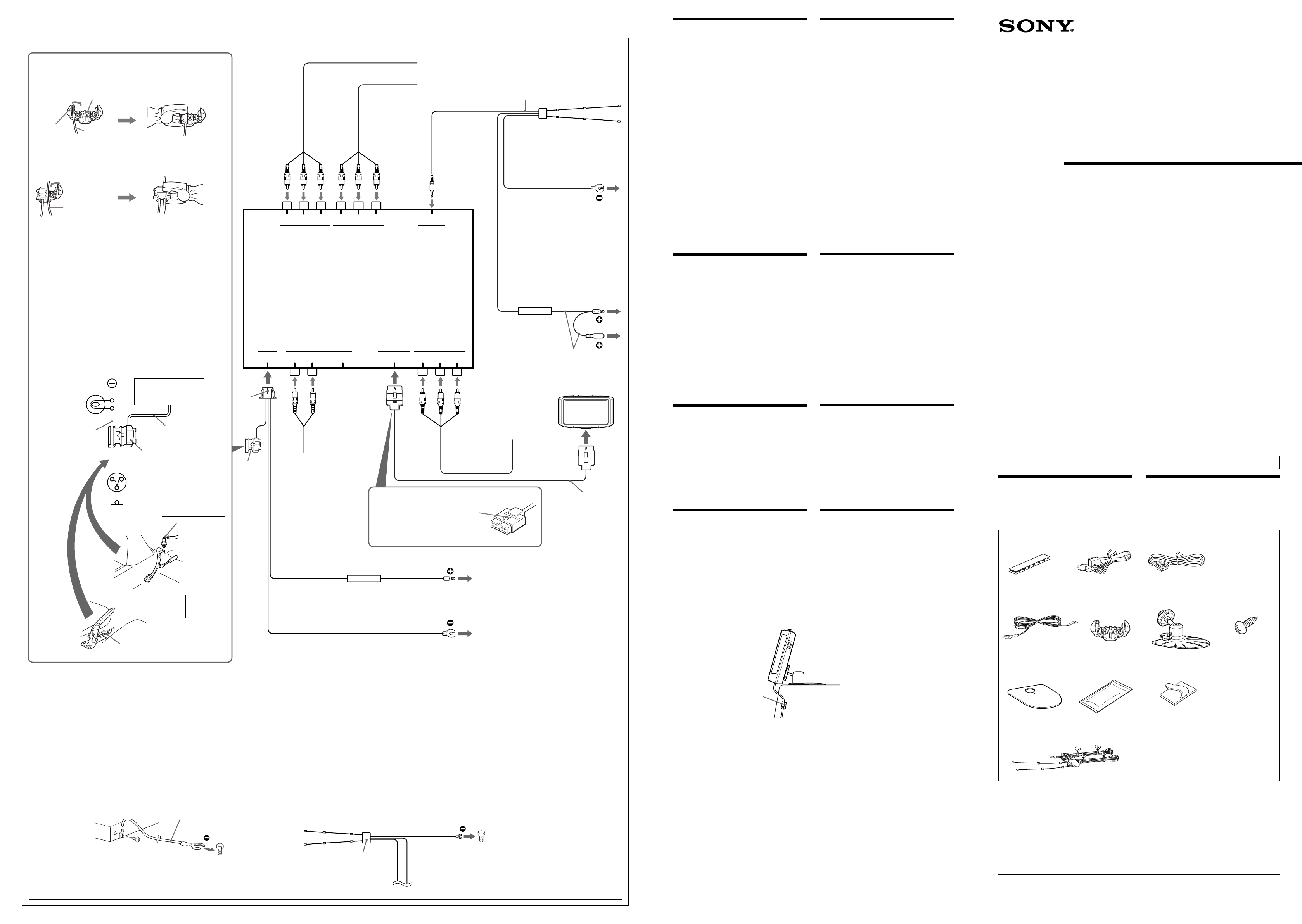
Attach to the tap the end of the parking cord (Green).
1
§ ⁄ – Y‹Cƒb –¤fi ‰u¡]”æƒ ¡^¥‰” ¡C
5
Stopper
§¤‰u „
Fix the tap to the parking cord in a suitable position on
2
the parking brake switch cord as illustrated.
Parking cord (Green)
–¤fi ‰u¡]”æƒ ¡^
ƒp„ˇ' ¥ ¡A§ ⁄ – Y'T'wƒb –¤fi»s ˚¶}ˆ ‰u“” A• ƒ ‚m¡C
Parking brake switch cord
–¤fi»s ˚¶}ˆ ‰u
Note
If the parking brake switch cord is too thin, connect the parking cord to
the parking brake switch cord directly without using the tap.
ø
ƒp“G –¤fi»s ˚¶}ˆ ‰u⁄ † ¡A¥i⁄£¥˛⁄ – Yƒ “‰– –N –¤fi ‰u– ƒ –¤fi
»s ˚¶}ˆ ‰u⁄W¡C
Connecting the parking cord
Be sure to connect the parking cord (Green) to the parking brake
switch cord. The mounting position of the parking brake switch cord
depends on your car. Refer to the system connection diagram below
and consult your car dealer or your nearest Sony dealer for further
details.
‡s– –¤fi ‰u
¨¥†–N –¤fi ‰u¡]”æƒ ¡^– ƒ –¤fi»s ˚¶}ˆ ‰u⁄W¡C –¤fi»s ˚¶}ˆ
‰u“”ƒw‚¸ƒ ‚m ł–z“”¤T¤fiƒ 'w¡C¥i ƒ ⁄U›–“”¤t†˛– ‰u„ˇ¡A¤ˆƒV–z“”
¤T¤fi‚g P '˛·N“æƒV Sony ‚g P «t‚ ¡C
Battery power
»W„qƒ „q•‰
TV tuner unit
Parking brake
warning light
–¤fi»s ˚˜ §i¿O
Parking brake
switch cord
–¤fi»s ˚¶}ˆ ‰u
Body ground
¤fi¤›– ƒa
Hand brake type
⁄ ¡]' ¡^«b¤fi«‹
Parking brake switch cord
„q ł “”‰ ¿ „
Parking cord (Green)
–¤fi ‰u¡]”æƒ ¡^
5
Parking brake switch
–¤fi»s ˚¶}ˆ
Foot brake type
‚}¡]‰æ¡^«b¤fi«‹
–¤fi»s ˚¶}ˆ ‰u
2
Green
”æƒ
5
Parking brake
switch cord
–¤fi»s ˚¶}ˆ ‰u
‡s–Connections
RCA pin cord (not supplied)
RCA ·¡⁄ ‰u¡]«D“ ¥ ¡^
RCA pin cord (not supplied)
RCA ·¡⁄ ‰u¡]«D“ ¥ ¡^
VIDEO L R
POWER NAVI IN MONITOR OUT OUTPUT
from navigation system
¤ ƒ ƒV¤t†˛
AUDIO
INPUT 2 INPUT 1 ANT IN
VIDEO AUDIO
RCA pin cord
(not supplied)
RCA ·¡⁄ ‰u¡]«D“ ¥ ¡^
VIDEO L R
SONY NAVI(NVX)
Fuse (3 A)
«O I • (3 A)
AUDIO
Disconnecting the connector
Pull out while pressing this catch.
´_¶}– ‰u „
« ƒ„´Œƒ'fi ´_¶}¡C
Red (2 m) (78 3/4 in.)
‹ıƒ ‰u (2 m)
Black (2 m) (78 3/4 in.)
¶´ƒ ‰u (2 m)
from Video CD or camcorder
¤ ƒ ł”—'æ…v '˛˜Æ„‡¿ ›
(5 m) (196 7/8 in.)
LR
VIDEO
AUDIO
!¡
First connect the black ground lead,
then connect the red power input
lead.
To a metal point of the car.
¥ ‡s– ¶´ƒ – ƒa‰u¡A M«Æ‡s– ‹ıƒ „q
•‰¿Ø⁄J„q‰u¡C
– ¤ ¤T¤fi“”“ ˜ ‡¡⁄ ¡C
Black (5 m) (196 7/8 in.)
¶´ƒ ‰u (5 m)
Be sure to connect the black ground
lead first.
To the +12 V power terminal which is
energized in the accessory position of
the ignition key switch.
⁄@'w›n¥ ‡s– ¶´ƒ “”– ƒa‰u¡C
– ¤ ´I⁄ı˘_ ˝¶}ˆ »†§Uƒ ‚m“”‡q„q“”
+12 V „q•‰” ⁄l¡C
Fuse (1 A)
«OI• (1 A)
Red (5 m) (196 7/8 in.)
‹ıƒ ‰u (5 m)
Use the connector which matches
the ACC adaptor figure of the car.
¤ˇ¥˛†¯ƒX¤T¤fi“” ACC¡]»†§U¡^ ƒ
‚m´ – „§˛“‹“”‡s– „¡C
Monitor
to rear passenger's TV or
monitor
– ƒ «Æfiy›…«¨„q ł '˛¯ª¥ „
RCA pin cord
(not supplied)
RCA ·¡⁄ ‰u
¡]«D“ ¥ ¡^
###
3
(3 m) (118 1/8 in.)
Be sure to connect the black ground lead first.
To the +12 V power terminal which is energized in
the accessory position of the ignition key switch.
¨¥†¥ – ¶´ƒ – ƒa⁄ ‰uƒ +12 V „q•‰” ⁄l¡]• ´I⁄ı`
¶}ˆ ‡B' »†§U‡]‡˘ƒ ‚mfi ƒ„” ⁄l‡q„q¡^¡C
First connect the black ground lead, then connect
the red power input lead.
To a metal point of the car.
¥ – ¶´ƒ – ƒa⁄ ‰u¡A M«Æ– ‹ıƒ „q•‰¿Ø⁄J⁄ ‰u¡A– ƒ
¤T¤fi“”⁄@› “ ˜ ´I¡C
Warning
Do not disassemble or remodel the unit.
This can cause electric shock, personal injury
or fire. Do not connect any other system’s
power supply cord to this unit’s power
supply cord directly. If you are in any doubt
about the safe installation of this unit, please
consult your nearest Sony dealer.
Do not damage any pipes, tubes, fuel tank
or electric wiring system when installing
this unit.
This can cause fire. Before drilling any holes
in car panels for the installation of this unit,
make sure the installation will not damage
any hidden car parts.
Do not use any nuts or bolts connected to
the steering linkage, fuel supply or
braking systems.
This can cause fire or loss of control of the
car.
Do not mount the monitor where it will
interfere with the airbag system.
This may cause the airbag to malfunction
during a crash causing injury to the
passenger.
Caution
• This unit is designed for negative ground
12 V DC operation only.
• Before making connections, disconnect the
ground terminal of the car battery to avoid
short circuits.
• Connect the red power input leads only
after all other leads have been connected.
• Be sure to connect the red power input lead
to the positive 12 V power terminal which
is energized when the ignition key is in the
accessory position.
• Be sure to fix the TV antenna with the
double-sided tape.
• Run all ground wires to a common
ground point.
Fuse replacement
If the fuse blows, check the power connection
and replace the fuse. If the fuse blows again
after replacement, there may be an internal
malfunction.
Warning
Use a fuse with the specified amperage
rating. Use of a higher amperage fuse may
cause serious damage to the unit.
Handling the connected
cords
After installing and connecting the unit, use
the supplied clamp to tie up the cords in a
bundle so it will not interfere with normal
driving operations.
It is very dangerous for the cords to
become tangled with the gearshift lever
during driving.
Use the supplied clamp
up the cords on the passenger seat
side.
00
0 to secure
00
˜§i
‰—⁄¯' ¤ł'˛§ ‚¸¡C
‡o•|‡yƒ¤„q »¡A¤ ¶¸'˛ _⁄ı¡C‰—⁄¯§ §O“”
„q•‰‰u“‰– »P¥» “”„q•‰‡s– ¡Cƒp“G„ ¥» “”
ƒw¥ ƒw‚¸¤Sƒ‡§ ·⁄¡A‰—·N“æƒV Sony ‚g P «t
‚¡C
ƒw‚¸¥» fi ‰—⁄¯•l¶¸ ” ¡A‡n” ¡A“o‰c
'˛¥‹‰u¤t†˛¡C
‡o•|‡yƒ¤ _⁄ı¡Cƒb¤T¤fi» “ “O⁄Wƒw‚¸¥»
ƒ » ˘p⁄ «e¡A ‡‰T«Oƒw‚¸§@•~⁄£•|•l¶¸¤T¤fi“”
«D'œ¯S‡¡¥ ¡C
‰—⁄¯› §U»P⁄ŁƒV‰L`p ˚ ”c¡A¤ “o¤t†˛
'˛«b¤fi¤t†˛‹ ‡s“”`‡·U'˛`‡fiŒ¡C
‡o•|‡yƒ¤¤T¤fi _⁄ı'˛¥¢––¡C
⁄¯–N¯ª¥ „‚¸ƒbƒ‡ˆ“«O Ifi ‡U ˚§@“”ƒa
⁄Ł¡C
‡o•|ƒb o¥˝¤fi” fi ¤ˇ«O Ifi ‡U¥¢˘F¡A–qƒ
¶¸fi‘›…«¨¡C
“‘•N
• ¥» ¶¨¤ ›t•¥– ƒa 12 V “‰‹y §@ƒ ‡]›p¡C
• – ‰u«e‰—´_¶}¤T¤fi»W„qƒ “”– ƒa” ¥H§K u
‚¡C
• ‹ıƒ „q•‰¿Ø⁄J⁄ ‰u¥uƒ‡¤ ¥L¥ ‡¡⁄ ‰u§¡⁄w‡s
– ƒn«Æ⁄~fl ‡s– ¡C
• ‹ıƒ „q•‰¿Ø⁄J⁄ ‰u ¨¥†– ƒ • ´I⁄ı˘_ ˝‡B'
»†§U‡]‡˘ƒ ‚mfi ‡q„q“”¥¿ 12 V „q•‰” ⁄l⁄W¡C
• ¨¥†¥˛´ø›–‰ƒ–a'T'w„q ł⁄ ‰u¡C
• ¥ ‡¡– ƒa‰u§¡⁄ ƒ ⁄@⁄‰ƒ@– ƒa´I¡C
§·««OI•
ƒp“G«O I •”†´_¡A«h ¸‹d„q•‰– ‰u¤ˆ§ ·«
«O I •¡Cƒp·««ÆƒAƒ‚”†´_¡A¤”⁄\¥ifl ƒsƒb⁄”‡¡
‹G» ¡C
˜§i
›n¥˛ˆB'w„q‹y–j« “”«O I •¡Aƒ “„q‹y–j
« “”«O I •«h•|˜Y›«•lˆa¥» ¡C
‡B†z– ƒn“” ‰u
¥» ƒw‚¸¡B– ‰u§„†ƒ¡A¥˛' t‡˘“”‰u§¤§
‰u⁄ªƒ¤⁄@§ ¡A¤ˇ¤ ⁄£›P' ⁄z´Z¥¿–‘“” r p
§@¡C
¤fiƒ pfi ¡A ‰u»P¯ ‡t§ ˜æƒb⁄@ _‹O⁄Q⁄
ƒM I“”¡C
¥˛¥» t‡˘“”‰u§¤
aƒa'T'wƒb›…«¨fiyƒ fi˙¡C
00
0 § ‰uƒw¥ ¥i
00
Mobile Color TV
Installation/Connections
ƒw‚¸¡ ‰u‚ ⁄§‡s–
XTL-750W
Sony Corporation 1999 Printed in Japan
Parts for installation
and connections
The numbers in the list are keyed to those in
the instructions.
1 × 2
4 567 × 5
23
ƒw‚¸⁄˛‡s– ¥˛„s‡¡¥
“ ⁄”§˙‚„¥H»¡'œfi “”§˙‚„‹ •˙¡C
Notes
• Be sure to connect the power input cord after all other cords
have been connected.
• The NAVI IN jack is for navigation systems only.
Do not connect any system other than a navigation system.
• As of January 1999, the Sony navigation system is not
available.
How to reduce the noise during radio reception
If you use the supplied TV antenna instead of the original glass antenna, there will be
alternator noise during radio reception. In this case, earth the TV tuner unit to a metal point
of the car with the supplied earth cord 4 as shown in the illustration left.
And ground the TV antenna to a metal point of the car (with the supplied ground cord)
near the antenna as shown in the illustration at right.
Example
¥¤
TV tuner unit
„qł‰¿„
4
to a metal point of the car
– ƒ ¤T¤fi“”⁄@› “ ˜ ´I
ø
• „q•‰¿Ø⁄J⁄ ‰u ¨¥†ƒb¤ ¥L' ƒ‡ ‰u§¡⁄w– ƒn«Æ⁄~‡s– ¡C
• NAVI IN ·¡fiy¶¨¤ t‡˘ƒ‡ ƒV¤t†˛⁄~¥˛¡C⁄¯– ¥ ƒ §O“”‰u‚ ¡C
• 1999 ƒ~ 1 ⁄º⁄§«e¡Aƒb‹Y¤˙¤¨ƒ{¥«‡ı⁄£fl Sony ƒV¤t†˛¡C
¯¥ƒ‹› fi ƒpƒ · ⁄p ‚`n
ƒp“X¥˛“ –a“”„q ł⁄ ‰u¥N· › ‹`… ¡⁄ ‰u¡A«h• ¯¥ƒ‹› fi ¡A–N o¥˝¥ ‹y ‚`n¡Cƒ„fi ¡A‰—
ƒp¥“„ˇ' ¥ ¥˛“ –a“”– ƒa‰u 4 –N„q ł‰ ¿ ‚¸‚m– ƒa¤ ¤T¤fi“”“ ˜ ‡¡⁄ ¡C
–N„q ł⁄ ‰u– ƒa¤ ƒp¥k„ˇ' ¥ “” a“æ⁄ ‰u“”¤T¤fi⁄W“ ˜ ‡¡⁄ ¡]¥˛“ –a“”– ƒa ‰u¡^¡C
First connect the black ground lead,
then connect the red power input lead.
To a metal point of the car.
¥ ‡s– ¶´ƒ – ƒa‰u¡A M«Æ‡s– ‹ıƒ “”„q•‰¿Ø
⁄J„q‰u¡C
– ¤ ¤T¤fi“”“ ˜ ‡¡⁄ ¡C
Black
¶´ƒ ‰u
!¡
to a metal point of the car
– ƒ ¤T¤fi“”⁄@›“˜´I
0
Notes
• Secure the connecting cords away from the
seat adjustment rails and the door frame.
• Make sure all other electric devices such as
brake lights and headlights are working
properly after installation is complate. Check
also that indicators turn on and the horn
works properly.
ø
• 'T'w‡s– ‰u¤ˇ¤ »•´ fiyƒ ‰ ‚‘›y'M¤fi“øfi ¡C
• ›n‰T«O¥» ƒw‚¸§„†ƒ«Æ¡A«b¤fi¿O¡B«e¿O ¥¤ ¥L
' ƒ‡„q „‡£⁄u§@¥¿–‘¡A¤ˆ ¸‹d« ¥ ¿O“”– ‡q'M
‡ ¥z⁄u§@‹O§_¤}ƒn¥¿–‘¡C
890 × 3
!¡
*I-3-866-746-11*(1)
Page 2
Installation ƒw‚¸
Before installing the
monitor
• This monitor is designed for safe operation
during driving.
• Be sure to install the unit in a suitable
position. Improper installation can cause a
serious accident.
• Be sure not to install the unit where it will
interfere with the airbag system.
Tips on the mounting location
• Choose the mounting location of the
monitor unit carefully.
• In order to prevent rattling from the
vibration of the car, make sure that the
back or the bottom of the monitor unit is
touching the mounting surface when
mounting the monitor unit.
Caution on installation
Do not install the unit:
— on a dashboard.
— in a hot place, subject to direct sunlight,
near a heater or in a car with the windows
closed (especially in summer) or in an
extremely cold place.
— in a place subject to excessive dust,
moisture.
— in a place which could harm the
passenger.
— in a place which could distract the driver.
— on a door or the ceiling.
Notes
• Clean the mounting surface well with the
supplied cleaning cloth. (The cleaning cloth is
a disposable type.)
• Warm the mounting surface and the double-
sided tape to a roomtemperature of more than
20°C (68°F) and then press the base of the
stand with the double-sided tape attached,
firmly against the mounting surface.
• When tightening the screws, make sure that
the nearby wiring does not get caught.
• When drilling holes on the mounting surface,
make sure that there is nothing on the other
side.
¯ª¥ „ƒw‚¸⁄§«e
• ¯ª¥ „‹O‹ ⁄F r pfi “”ƒw¥ §@ƒ ‡]›p“”¡C
• ¨¥†ƒw‚¸ƒbƒX A“”ƒa⁄Ł¡Aƒw‚¸⁄£• •|⁄ o˜Y
›«¤˘‹G¡C
• ¯ª¥ „“”ƒw‚¸ ¨¥†⁄£§«ˆ“«O Ifi ‡U¤t†˛¡C
ƒw‚¸ƒ ‚m¶•“
• ¥†¶•⁄p⁄ ƒa¿ ”˚ ł „‚¸‚m“”ƒw‚¸ƒ ‚m¡C
• ‹¤¤¤¤T¤fifi¶˚…v¯T¡Aƒw‚¸”˚ ł „‚¸‚m
fi ¡A¥†¶•‰T»{”˚ ł „‚¸‚m“”›I‡¡'˛'‡ˆ ‹O§_
aƒ ƒw‚¸›–¡C
ƒw‚¸fi ¶•“‘•N
⁄£›n§ ‚¸‚mƒw‚¸ƒb¡G
— ¤T¤fi» ¿ “O⁄W¡C
— ⁄ … “”ƒa⁄Ł¡A“‰– • fig¤ ¶§¥œ¡A a“æ¥[… „
'˛–K‡‹ ¤fi ¡“”¤T¤fi⁄”¡]⁄ ¤ ‹OfiL⁄ ¡^'˛⁄
§N“”ƒa⁄Ł¡C
— ƒh„—¡A…Ø ª“”ƒa⁄Ł¡C
— •|¶¸fi‘¤ ›…«¨“”ƒ ‚m¡C
— •|“ ˆ“ r p“ “”ƒ ‚m¡C
— ¤fi“ø⁄W'˛¤T¤fi⁄ “Æ“O⁄W¡C
ø
• ¥˛“ –a“”†M… ¥‹ ¿ fi†bƒw‚¸“ ›–¡C¡]†M… ¥‹˜
' ' ‡B‚m«‹¡C¡^
• –Nƒw‚¸›–'M´ø›–´H‰ƒ–a¥[•¯„F 20¢J ¥H⁄W“”«˙
•¯¡A M«Æ§ ¶Kƒ‡´ø›–´H‰ƒ–a“” fiy´H¶Kˆ›ƒbƒw
‚¸›–⁄W¡C
• – ” `‡ • vfi ¡A¶•fld•N“ “æ“”„q‰u•|‡Q† ƒ ¡C
• ƒbƒw‚¸›–˘p⁄ fi ¡A⁄]¶•‰T»{›I›–‹O§_ƒ‡ ¥
¥¡C
Installing the monitor
Make sure the installation surface and
monitor position are suitable before
beginning installation. If you cannot find a
suitable mounting location, consult your car
dealer or your nearest Sony dealer before
installation.
ƒw‚¸¯ª¥ „
¶}'lƒw‚¸«e ‡‰T«Hƒw‚¸›–'M¯ª¥ „ƒ ‚m‹O
ƒX A“”¡Cƒp“G–z§ ⁄£¥X A• “”ƒ ‚m¡A¥iƒbƒw‚¸
«eƒV–z“”¤T¤fi‚g P '˛·N“æƒV Sony ‚g P «t
‚¡C
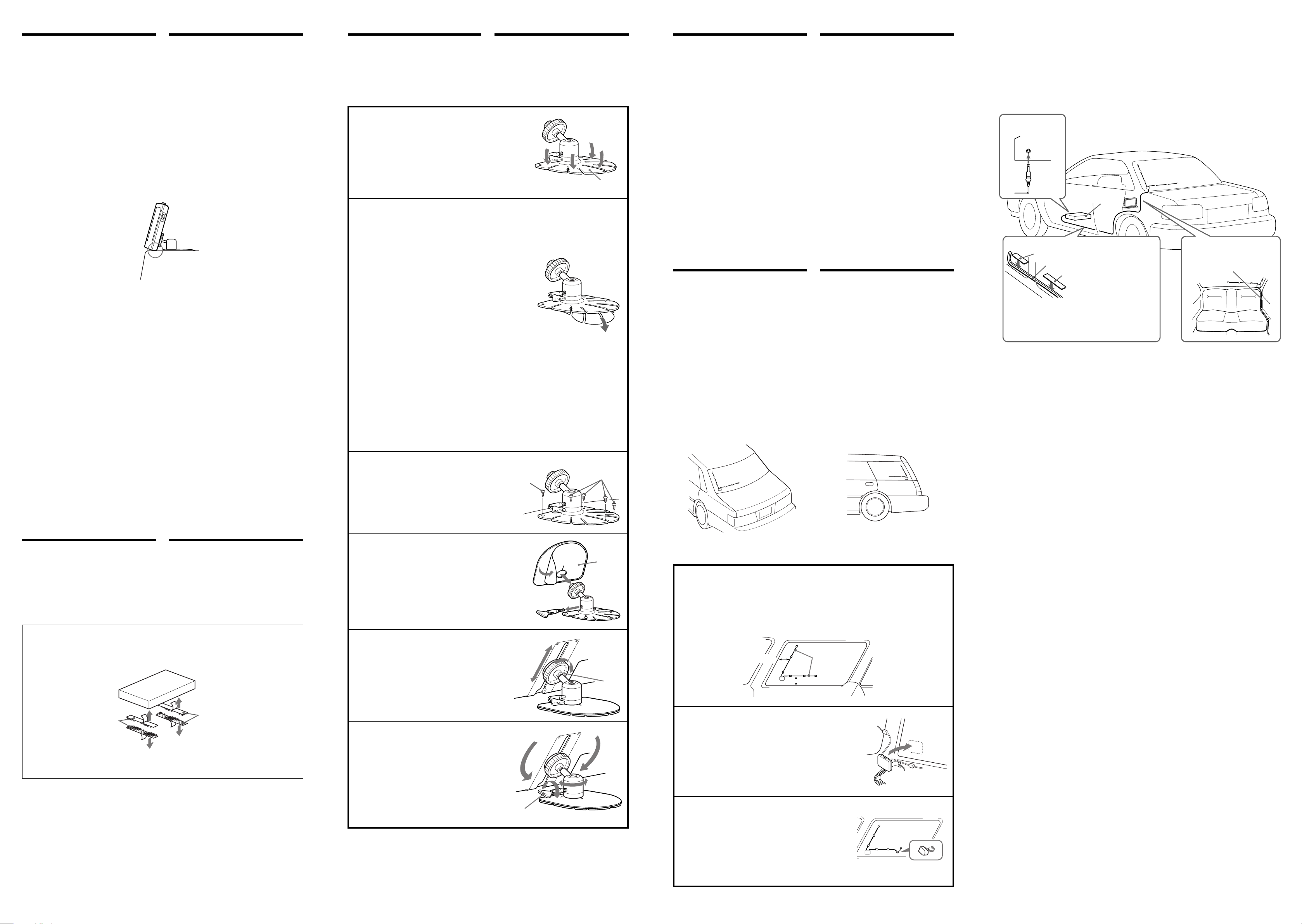
1 Choose the mounting position, then shape the
base of the monitor stand 6 to match the
mounting surface.
Bend the base gently so there are no gaps between the base
and the mounting surface.
¿ 'wƒw‚¸ƒ ‚m¡A M«Æ¥[⁄u¯ª¥ „‹['‡fiy 6¡A¤ˇ⁄§
»Pƒw‚¸›–⁄˙ t¡C
»·»·¯s§Ø'‡fiy¡A¤ˇ⁄§»Pƒw‚¸›–⁄§¶¡¤Sƒ‡¶¡» ¡C
2 Clean the mounting surface well with the supplied cleaning cloth 9.
(The cleaning cloth is disposable.)
¥˛ t‡˘“”†M… ¥‹ 9 ¥J† ¿⁄z†bƒw‚¸›–¡]†M… ¥‹‹O⁄@ƒ‚'˚“”¡^¡C
3 Peel off the protective film from the base of
the monitor stand 6 and attach the base to
the mounting surface.
Make sure the base attaches to the mounting surface
completely.
Notes
• The double-sided tape will not stick firmly if the mounting
surface temperature is less than 20°C (68°F). Use a
hairdryer, etc. to warm up the mounting surface before
mounting.
• Consider carefully the mounting position beforehand. If
you change the position soon after mounting the doublesided tape will be weakened.
• When removing the monitor stand, preheat the mounting
surface with a hairdryer then slowly peel up to remove.
›Ø¥h¯ª¥ „'‡fiy 6 “”«O¯@`¡‰⁄¡A§ '‡fiy¶KƒX' ƒw
‚¸›–¡C
›n‰T«O'‡fiy§„¥ ¶Kƒbƒw‚¸›–⁄W¡C
ø
• ƒw‚¸›–“”•¯« ƒp“G‹O§C' 20¢J¡A´ø›–´H‰ƒ–a«K¥ifl ⁄£fl ´H¶K
¤c¡Cƒw‚¸«e¡A‰—¥˛§j›• ¥ „ƒw‚¸›–¥[… ⁄@⁄U¡C
• ¶•„w¥ ¥J† ƒaƒ …{„Lƒw‚¸ƒ ‚m¡C⁄@¥„´H¶K⁄W⁄Fƒ ⁄S§ ¯ ƒw‚¸ƒ
‚mfi ¡A´ø›–´H‰ƒ–a“”´H '˚–N•|· §C¡C
• ›n¤ł⁄U”˚ ł „‹[fi ¡A‰—¥˛§j›• ¥[… ⁄@⁄Uƒw‚¸›–¡A M«Æ‰w‰wƒa
›Ø¶}´H‰ƒ›–§ ¥ƒ¤ł⁄U¤ ¡C
4 Fix the stand with the supplied screws 7.
Note
Before drilling holes in the mounting surface, make sure
there is nothing behind the dashboard.
¥˛' t‡˘“”`‡ v 7 'T'w¯ª¥ „‹[¡C
ø
ƒw‚¸›–˘p⁄ «e›n‰T«O» “ “O«Æ¤Sƒ‡¥ ƒ “FƒŁ¡C
7
6
7
Tips on mounting TV
antennas
• Do not install these antennas on the
windshield. They are for rear window
installation only.
• Make sure the bases of the antennas are fixed
securely before driving the car.
• Tighten the screws occasionally in case the
screws become loose.
• Do not clean the antennas with alcohol,
benzine, thinner, gasoline or wax. These
cleaners may deform or damage the antennas.
• Position these antennas where they can't
interfere with other devices such as a car
radio or cellular phone.
• If your car radio antenna is the rear window
type, there may be interference during AM
reception. Position the antennas so as not to
interfere with AM reception.
• There may be disturbances in the picture
when you are:
— among tall buildings.
— near overhead wires or a power line.
— close to a flying airplane.
— close to a moving train.
— in the mountains or far from a TV station.
— in a tunnel.
— near an amateur ham radio or radio station
antenna.
Mounting the TV
antenna
Notes
• Install the bases of the TV antennas on as flat
a part of the rear window as possible so the
antennas will not fall off.
• Dry the mounting surface completely before
mounting in case the humidity is high.
• Warm the mounting surface before mounting
in case of low temperature in order to attach
the bases firmly.
• Do not apply force to the antennas or allow
them to become wet within 24 hours after
attaching the bases.
• The base of the TV antenna has an antenna
booster selector. Set the antenna booster
selector to ON if the signal is weak. The
default selector position is set to OFF.
Mounting example/ƒw‚¸¥ ¤
ƒw‚¸„q ł ⁄ ‰u“”·£¥
• ‰—⁄¯§ ƒ„ˆ ⁄ ‰u‚¸ƒb ›•‹`… ⁄W¡A¥ufl §@«Æ ¡
ƒ¡ƒw‚¸¡C
• ¶}¤fi«e›n‰T«O⁄ ‰u fiy“”¥i a'T'w¡C
• fi–‘–”`‡v¤⁄`‡v“Q˚¡C
• ⁄¯¥˛ s”º¡B»·¤T“o¡B }˜ fl¡B¤T“o'˛˜œ‹~⁄
‰u¡C‡o¤˙‹~” fl•|¤ˇ⁄ ‰u¯ §˛'˛•l¶¸¡C
• ⁄ ‰uƒw‚mƒb⁄£•|⁄z´Z¤T¤fiƒ‹› '˛«K˜ ƒ¡† ˚
„q‚ ¥‡]‡˘“”ƒa⁄Ł¡C
• ƒp“G–z“”¤T¤fiƒ‹› ⁄ ‰u‹O«Æ ¡ƒ¡“”¡A‰ ·T–
ƒ‹fi ¥ifl ƒ‡⁄z´Z¡A‹ ƒ„⁄ ‰u“”¥‹‚m⁄ ›n⁄£⁄z´Z
‰ ·T„q¥x“”– ƒ‹¡C
• • –z“”¤T¤fi‡B' ¥H⁄U–¡“pfi ¥ifl •|¥X†{„ˇ„‡⁄z
´Z¡G
— ƒb “… ⁄j•H⁄§¶¡¡C
— a“æ‹[“¯‰u'˛„q⁄O‰u¡C
— – “曂ƒ ⁄⁄“”›‚ fi ¡C
— – “æƒ p⁄⁄“”¤T¤fifi ¡C
— ƒb‚s⁄s⁄⁄'˛»•´ L‰u„q¥x¡C
— ƒb G„D‚ ¡C
— – “æ•~§E L‰u„q•Rƒn“ “”ƒ‹› '˛ L‰u„q¥x
“”⁄ ‰u¡C
ƒw‚¸„q ł⁄ ‰u
ø
• ⁄ ‰u fiy‚¸ƒb«Æ ¡” ¥ifl ¥›“”ƒa⁄Ł¡A¥H§K⁄ ‰u
“”¶^‚¤¡C
• ƒb ª« ‚ß⁄jfi ¡A‰—ƒbƒw‚¸«e„ '‡ ¿⁄zƒw‚¸›–¡C
• ƒb•¯« ‚ߧCfi ¡A‰—ƒbƒw‚¸«e¥[•¯ƒw‚¸›–¡A¥H«K
ˆ›'Tƒw‚¸‚¸‚m¡C
• fiyƒw‚¸«Æ 24 ⁄pfi ⁄”¡A‰—⁄¯„ ⁄ ‰u‹I¥[ £⁄O'˛
¤ˇ⁄§¤ …Ø¡C
• „q ł⁄ ‰u“” fiy⁄W‚¸ƒ‡⁄ ‰u…W–j¿ „¡Cƒp“X
«H‚„⁄ fiz¡A¥i§ ⁄ ‰u…W–j¿ „‡]'w' ON¡C fl˚
fiu¿ ƒ ‚m‹O‡]'w' OFF ¡C
Wiring the antenna cords
Before wiring
• Avoid wiring locations subject to high
temperature.
• If there is alternator noise, keep the antennas
and cords away from the car wiring.
Wiring diagrams/‰u‚ „ˇ
to ANT IN
– ANT IN
TV tuner unit
„q ł‰ ¿ „‚¸‚m
Side step guard/ …“ø¶¥–Ł¯@“O
Antenna cord/⁄‰u ‰u
Side step guard/ …“ø¶¥–Ł¯@“O
Remove the side step guards and wire the
antenna cords under the floor rug.
¤ł⁄U …“ø¶¥–Ł¯@“O¤ˆ§ ⁄ ‰u ‰u¥‹‚mƒbƒa· ⁄W¡C
⁄ ‰u ‰u“”¥‹‰u
¥‹‰u«e
• ¥‹‰uƒ ‚m ‡` §K D¤ “•¯…v¯T¡C
• ƒpƒ‡‰ ¿ ‚`n¡A§ ⁄ ‰u'M ‰uƒP¤T¤fi“”¥‹‰u⁄
„j¶}¤ ¡C
Fix cords with adhesive tape
behind the rear seat.
' «Æfiy›I«Æ¥˛‰ƒ–a'T'w ‰u¡C
Installing the TV tuner
unit
Install the TV tuner unit under the passenger
seat or in the trunk compartment.
Avoid installing the TV tuner unit where it
will be subject to high temperatures, such as
from direct sunlight or hot air from the
heater.
Installing with the Velcro tape 1
Wipe off the dirt from the mounting
surface.
1
to the mounting surface
‡s– ¤ ”˚ ł „“ ›–
ƒw‚¸„q ł “”‰ ¿ „
§ „q ł ‰ ¿ „‚¸ƒb›…«¨fiyƒ ⁄U'˛ƒ §ı‰c
⁄”¡C
` §K§ ‰ „‚¸ƒb⁄ ¶§“‰– • fig¤ '˛ƒ‡¤
ƒ ¥[… „… “¯fi “” “•¯ƒ ‚m¡C
¥˛¥§ s¤º˘p•fˆ 1 ƒw‚¸
¿ fi†bƒw‚¸›–“”„—«fl¡C
1
5 Attach the supplied plastic cover 8 over
the base of the monitor stand.
§ t‡˘“”¶ fi˘‚n 8 ¶Kƒb¯ª¥ „‹['‡fiy⁄W¡C
6 Adjust the height.
When the monitor is at the right height, tighten the
clamp. To keep the monitor from rattling while
driving, make sure the back or bottom of the monitor
is resting firmly on the mounting surface.
‰ª“«
• ¯ª¥ „‡B' ¥¿‰T “«fi”'w.§¤ªT¡C¤T¤fiƒ p⁄⁄¯ª
¥ „⁄£–oƒ‡¥d `n¡A¤ ›I‡¡'‡‡¡ ¨¥†ˆ›'Tƒa'Ł aƒw
‚¸›–¡C
7 Adjust the angle.
Loosen the lever and adjust the angle. After this
adjustment, tighten the lever to fix the angle.
‰ª¤⁄«
– “Q⁄ § ¤ˆ‰ ª¤⁄« ¡A‰ ƒn«Æ¡A–”⁄§¥H'T'w¤⁄« ¡C
8
Clamp
»““O
Wipe off the dirt (dust, oil and moisture)
from the glass surface.
¿ fi— ‹`… ¡›–“”„—«fl¡]ƒ˙„—¡A“o“d¡A⁄
⁄ ¡^¡C
1 Decide the mounting location.
Consider carefully the mounting location. Make sure there is a distance of more than
10 cm from the antenna wire for optimum tuning capability.
¤M'wƒw‚¸ƒ ‚m¡C
¥†¶•¥J† ƒ …{ƒw‚¸ƒ ‚m¡C‹ fl –o‡ ¤˛‰ ¿ fl ⁄O¡A⁄@'w‰—¶Z´ ⁄ ‰u 10 ¢Q ¥H⁄Wƒw‚¸¡C
more than 10 cm (4 in.)
10 ¢Q ¥H⁄W
more than 10 cm (4 in.)
10 ¢Q ¥H⁄W
Antenna wire
⁄‰u
2 Stick the body of the antenna onto the glass.
If temperature is low, preheat the glass using a hairdryer, etc.
Set the antenna booster selector to ON in areas where the
signal is weak. The default selector position is set to OFF.
–N⁄ ‰u¥»¯Ø´H“ ƒb‹`… ¡⁄W¡C
ƒp“G•¯« ⁄ §C¡A‰—¥˛§j›• ¥§j… ⁄@⁄U‹`… ¡Cƒb«H‚„‚ßfiz“”ƒa
ˇ¡A¥i§ ⁄ ‰u…W–j¿ „‡]'w' ON¡Cfl˚fiu¿ „ƒ ‚m‹O‡]'w
' OFF¡]ˆ –…¡^¡C
Lever
ڤ
3 Stick the wire to the glass starting from the
body of the antenna and working out.
Arrange the antenna wires in straight lines out from
the antenna body.
–q– “æ⁄ ‰u¥»¯Ø _§ ⁄ ‰u“”„q‰u‡¡⁄ ‡£´H“ ƒb‹`
… ¡⁄W¡C
ƒ ⁄ ‰u¥»¯Øƒø¥X“”„q‰u‡¡⁄ ¡A¤ˇ§e“‰‰uƒafii¶} t‚m¡C
 Loading...