

Sony XRC-5103-R Service manual
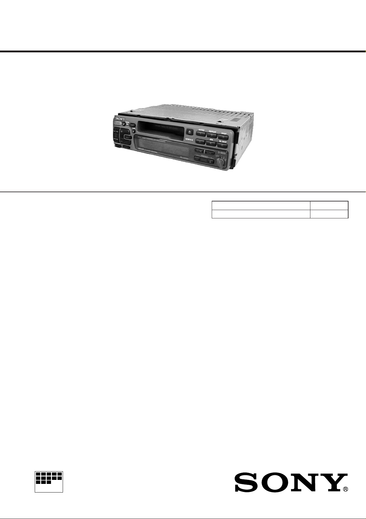
XR-C5100R/C5103R
SERVICE MANUAL
Photo: XR-C5103R
SPECIFICATIONS
Cassette player section
Tape track 4-track 2-channel stereo
Wow and flutter 0.08 % (WRMS)
Frequency response 30 – 18,000 Hz
Signal-to-noise ratio TYPE II, IV 61 dB
TYPE I 58 dB
Tuner section
FM
Tuning range 87.5 – 108.0 MHz
(XR-C5100R)
FM1, FM2: 87.5 – 108.0 MHz
FM3: 65.0 – 74.0 MHz
(XR-C5103R)
Antenna terminal External antenna connector
Intermediate frequency 10.7 MHz
Usable sensitivity 8 dBf
Selectivity 75 dB at 400 kHz
Signal-to-noise ratio 65 dB (stereo), 68 dB (mono)
(XR-C5100R)
63 dB (stereo), 65 dB (mono)
(XR-C5103R)
Harmonic distortion at 1 kHz 0.5 % (stereo), 0.3 % (mono)
Separation 35 dB at 1 kHz
Frequency response 30 – 15,000 Hz
Capture ratio 2 dB
AEP Model
UK Model
XR-C5100R
East European Model
XR-C5103R
Model Name Using Similar Mechanism NEW
Tape Transport Mechanism Type MG-25G-136
MW/LW
Tuning range MW: 531 – 1,602 kHz
LW: 153 – 281 kHz
Antenna terminal External antenna connector
Intermediate frequency 10.71 MHz/450 kHz
Sensitivity MW: 30 µV
LW: 50 µV
Power amplifier section
Outputs Speaker outputs
(sure seal connectors)
Speaker impedance 4 – 8 ohms
Maximum power output 40 W × 4 (at 4 ohms)
General
Outputs Telephone ATT control lead
Power amplifier control lead
Rear line out (1)
Tone controls Bass ±8 dB at 100 Hz
Treble ±8 dB at 10 kHz
Power requirements 12 V DC car battery (negative ground)
Dimensions Approx. 188 × 53 × 181 mm (w/h/d)
Mounting dimensions Approx. 182 × 53 × 164 mm (w/h/d)
Mass Approx. 1.2 kg
Supplied accessories Parts for installation and connections
(1 set)
Rotary commander RM-X4S
Front panel case (1)
MICROFILM
Design and specifications are subject to change without notice.
FM/MW/LW CASSETTE CAR STEREO

TABLE OF CONTENTS
1. GENERAL
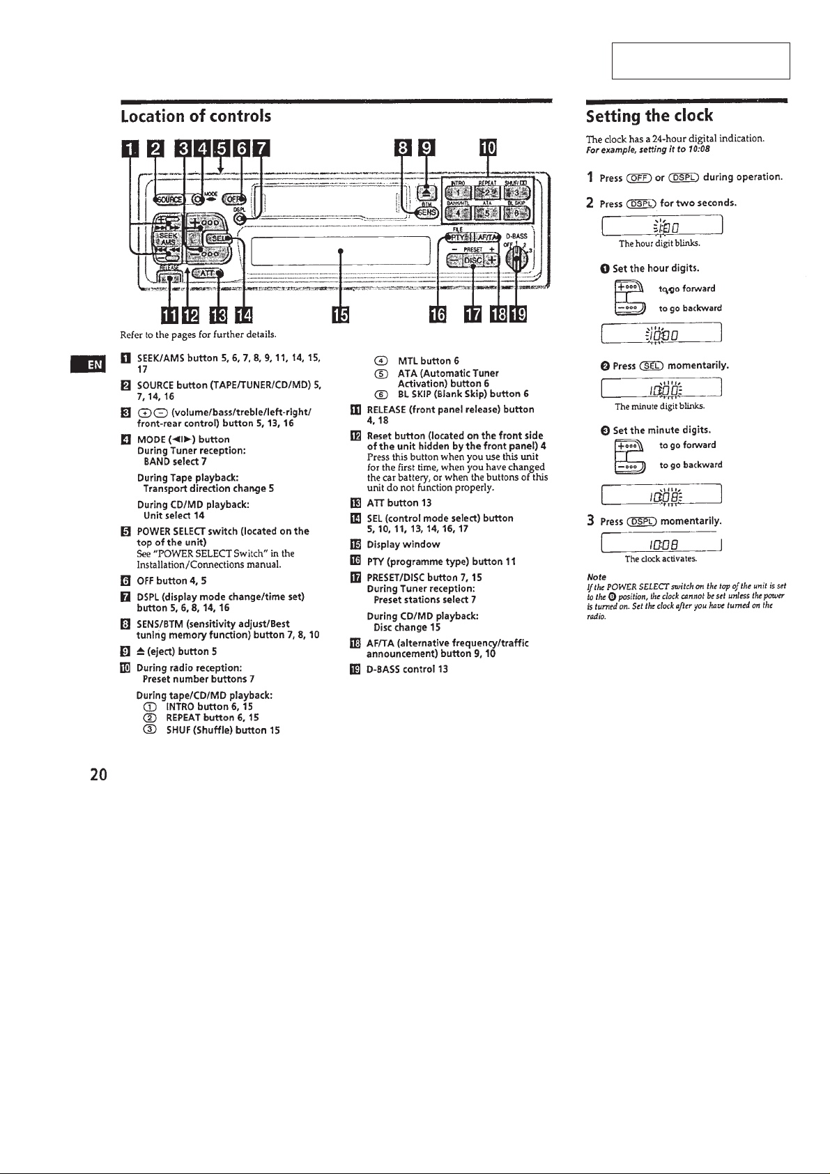
Location of Controls ....................................................... 3
Setting the Clock ............................................................. 3
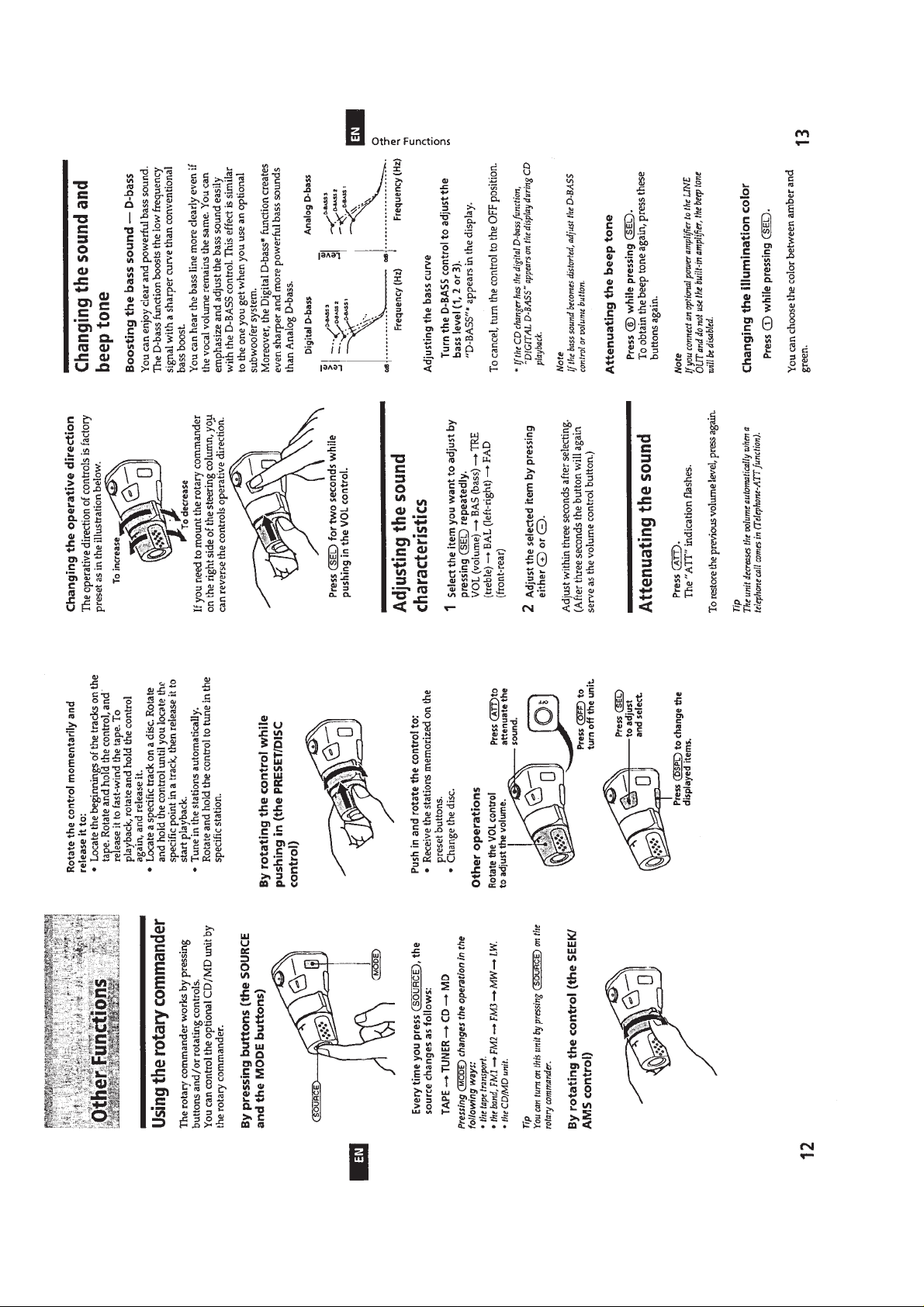
Using the Rotary Commander ........................................ 4
Adjusting the Sound Characteristics .............................. 4
Attenuating the Sound .................................................... 4
Changing the Sound and Beep Tone............................... 4
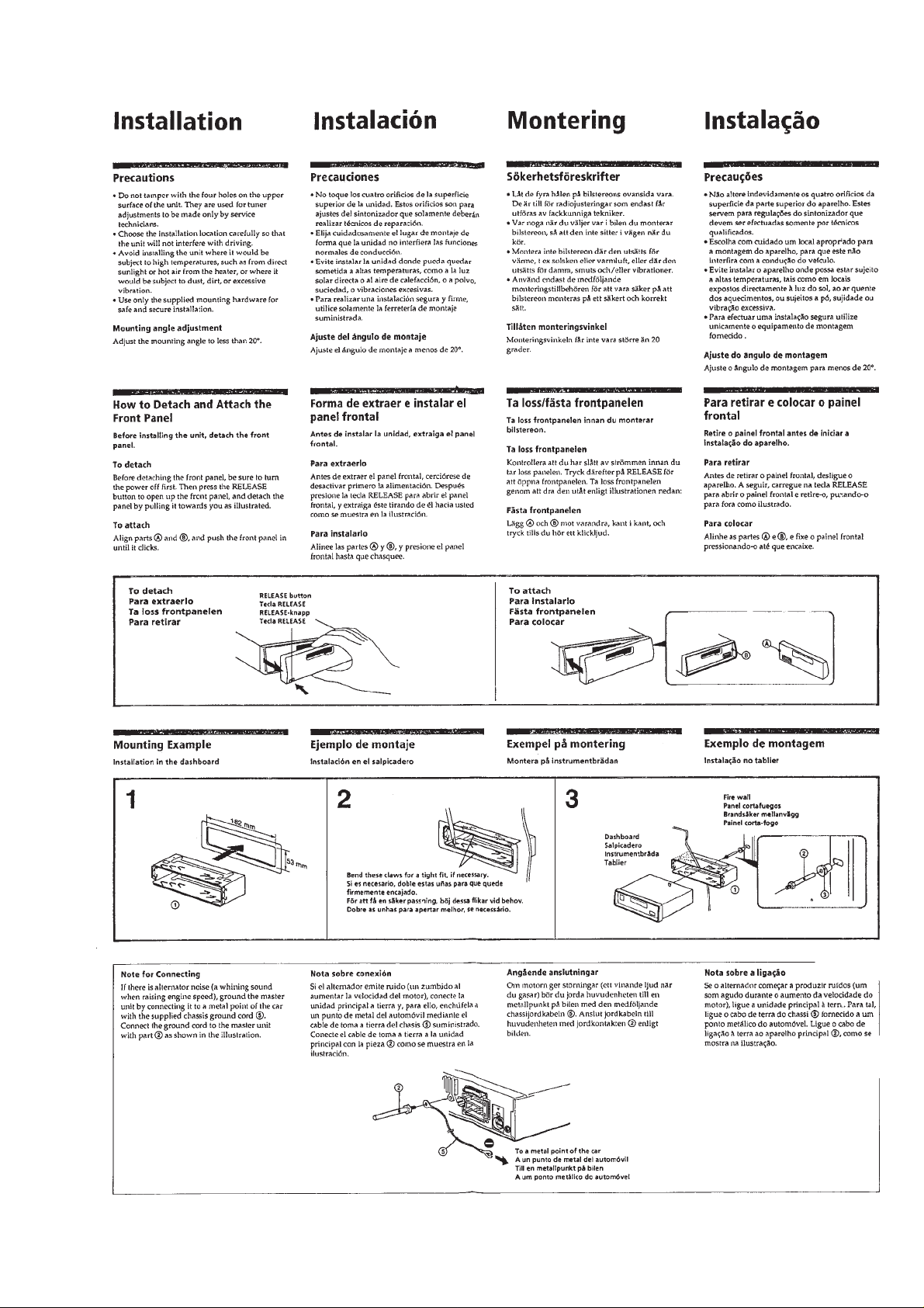
Installation....................................................................... 5
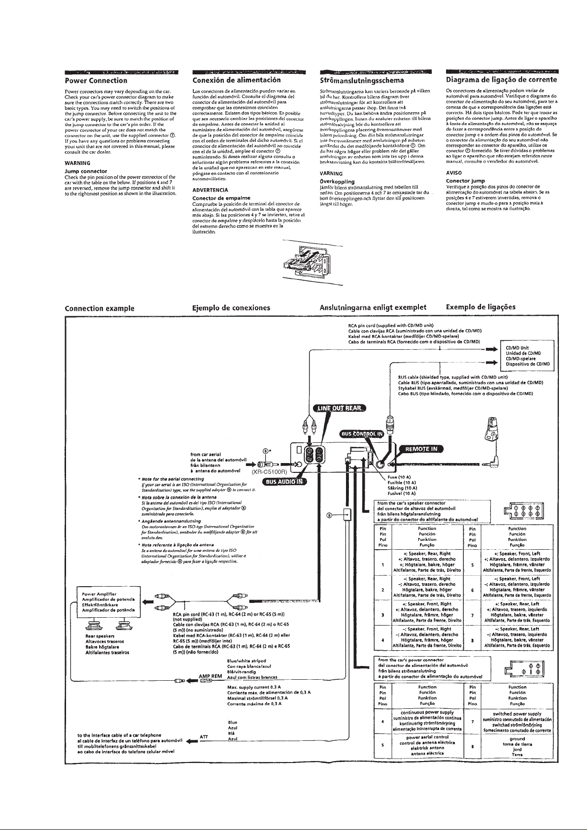
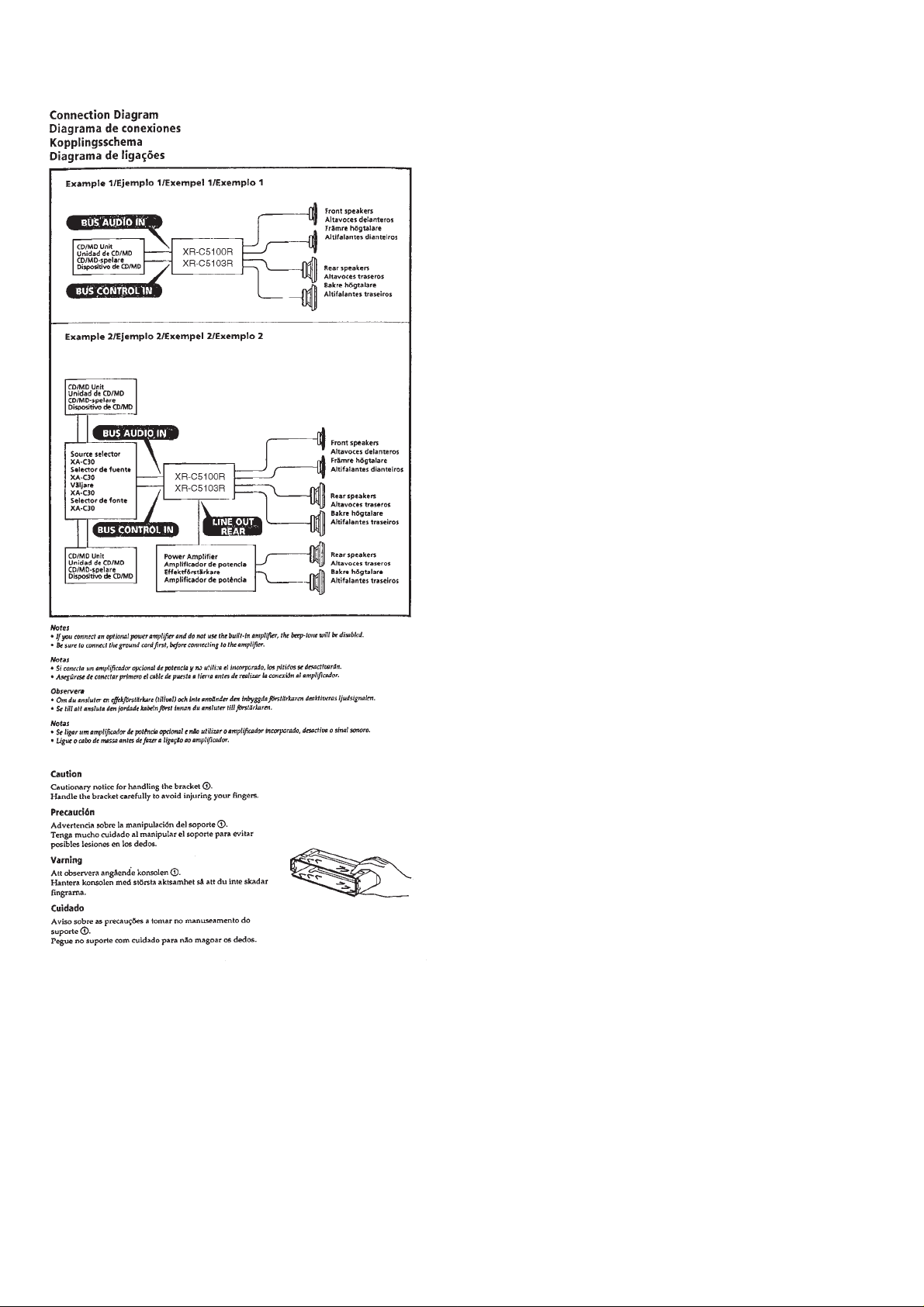
Connections ..................................................................... 6
2. DISASSEMBLY ......................................................... 9
3. ASSEMBLY OF MECHANISM DECK........... 11
4. MECHANICAL ADJUSTMENTS....................... 14
5. ELECTRICAL ADJUSTMENTS
Test Mode........................................................................ 14
Tape Deck Section .......................................................... 14
Tuner Section .................................................................. 15
6. DIAGRAMS
6-1. Printed Wiring Boards – MAIN Section – .................... 18
6-2. Schematic Diagram – MAIN Section –.......................... 21
6-3. Printed Wiring Board – PANEL Section – .................... 26
6-4. Schematic Diagram – PANEL Section –....................... 29
6-5. IC Pin Function Description ........................................... 31
Flexible Circuit Board Repairing
• Keep the temperature of the soldering iron around 270 ˚C during repairing.
• Do not touch the soldering iron on the same conductor of the
circuit board (within 3 times).
• Be careful not to apply force on the conductor when soldering
or unsoldering.
Notes on chip component replacement
• Never reuse a disconnected chip component.
• Notice that the minus side of a tantalum capacitor may be damaged by heat.
7. EXPLODED VIEWS ................................................ 37
8. ELECTRICAL PARTS LIST ............................... 40
– 2 –
SECTION 1
GENERAL
This section is extracted from
instruction manual.
– 3 –
– 4 –
– 5 –
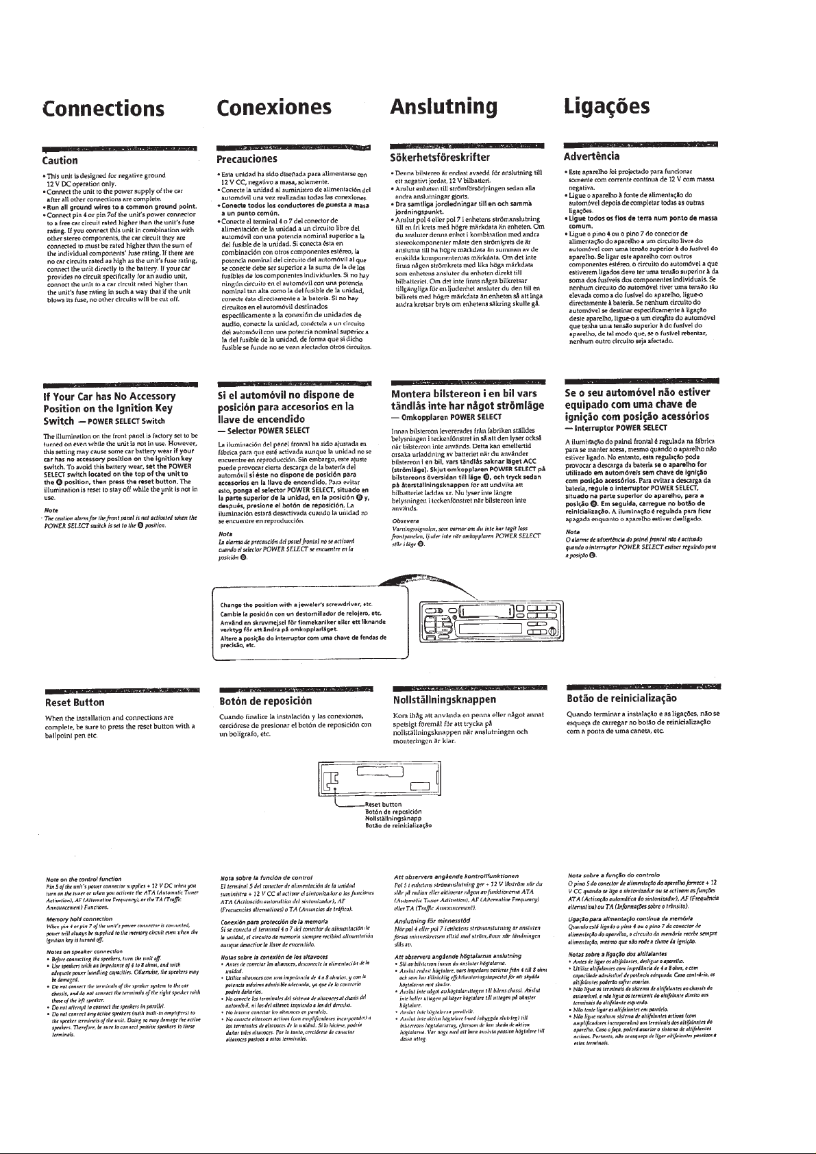
– 6 –
– 7 –
– 8 –
SECTION 2
1
2
2
1
3
cover ass’y
DISASSEMBLY
Note: Follow the disassembly procedure in the numerical order given.
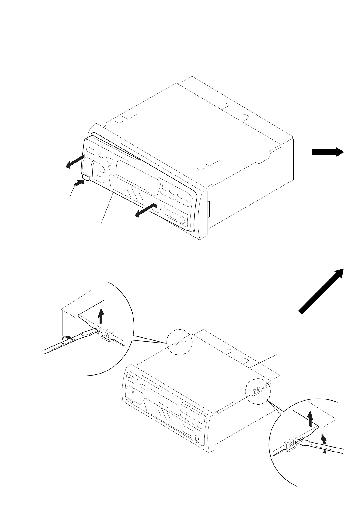
FRONT PANEL ASS’Y
1
Push the button
(release).
A
COVER ASS’Y
2
Remove the front panel ass’y
to the direction of the arrow
A
.
– 9 –
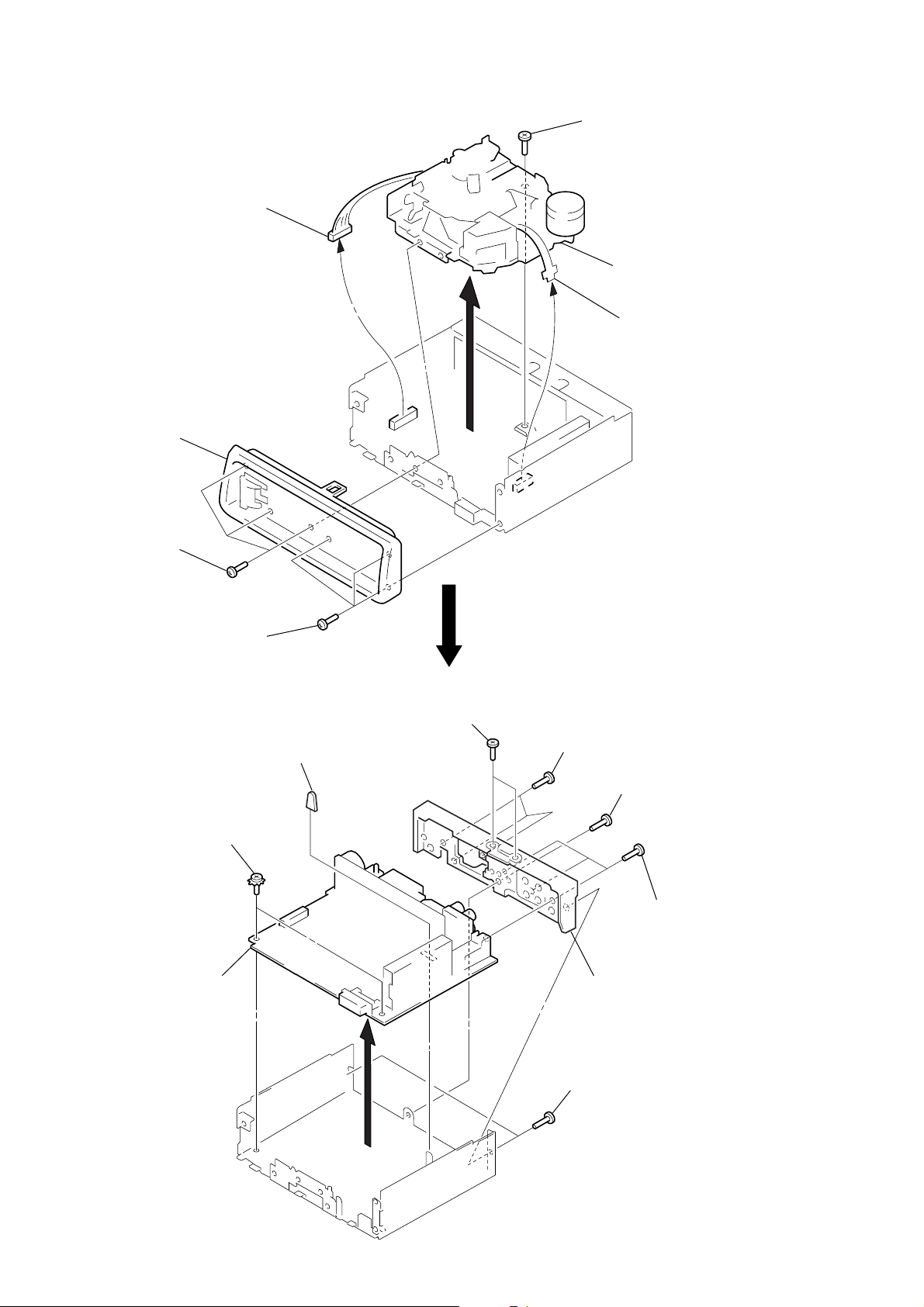
SUB PANEL, MECHANISM DECK (MG-25G-136)
e
3
connector
(CN352)
2
sub panel
1
three screws
(PTT2.6
×
8)
5
screw
(PTT2.6
×
6
mechanism deck
(MG-25G-136)
4
flexible flat cabl
(CN351)
6)
1
three screws
(PTT2.6
MAIN BOARD, HEAT SINK
3
two ground point
screws
4
main board
×
8)
2
rubber cap (25)
6
two screws
(PTT2.6
×
14)
5
three screws
(PTT2.6
1
7
×
10)
screw
(PTT2.6
heat sink
×
8)
5
three screws
(PTT2.6
×
10)
– 10 –
1
two screws
(PTT2.6
×
8)
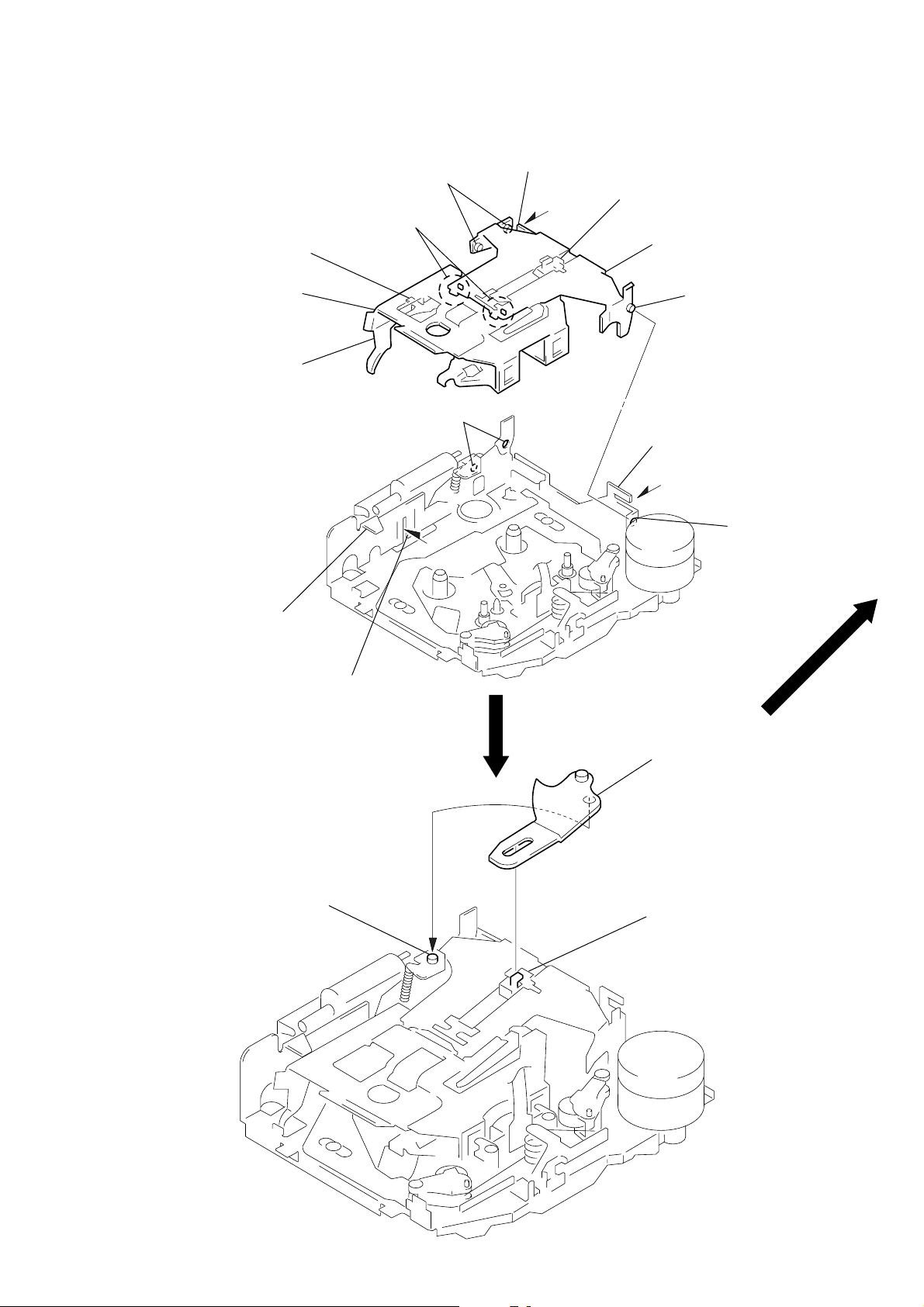
SECTION 3
2
Move the arm (suction) in the arrow
direction and fit on projection.
1
Fit the arm (suction) on the shaft.
projection
ASSEMBLY OF MECHANISM DECK
Note: Follow the assembly procedure in the numerical order given.
HOUSING
4
Fit claw on B part.
3
Put the housing
under A part.
housing
5
Fit projection on C part.
2
Install the hanger onto
two claws of the housing.
C
part
7
Holder the hanger by bending the claw.
1
Install the catch to the hanger.
hanger
6
Fit projection on D part.
8
Hold the hanger by
bending the claw.
D
part
ARM (SUCTION)
A
part
B
part
– 11 –
 Loading...