

Sony XR-5300-RV Service manual

XR-4300RV
/
C5300RV
SERVICE MANUAL
Ver 1.1 2001.05
Photo: XR-C5300RV
SPECIFICATIONS
Cassette player section
Tape track 4-track 2-channel stereo
Wow and flutter 0.08 % (WRMS)
Frequency response 30 – 18,000 Hz
Signal-to-noise ratio
Cassette type
TYPE II, IV 61 dB
TYPE I 58 dB
Tuner section
FM
Tuning range 87.5 – 108.0 MHz
Aerial terminal External aerial connector
Intermediate frequency 10.7 MHz/450kHz
Usable sensitivity 8 dBf
Selectivity 75 dB at 400 kHz
Signal-to-noise ratio 66 dB (stereo),
Harmonic distortion at 1 kHz
Separation 35 dB at 1 kHz
Frequency response 30 – 15,000 Hz
MW/LW
Tuning range MW: 531 – 1,602 kHz
Aerial terminal External aerial connector
Intermediate frequency 10.7 MHz/450 kHz
Sensitivity MW: 30 µV
72 dB (mono)
0.6 % (stereo),
0.3 % (mono)
LW: 153 – 279 kHz
LW: 40 µV
AEP Model
UK Model
Model Name Using Similar Mechanism XR-C5300R
Tape Transport Mechanism Type MG-25G-136
Power amplifier section
Outputs Speaker outputs
Speaker impedance 4 – 8 ohms
Maximum power output 50 W ×
General
Outputs Audio output
Tone controls Bass ±9 dB at 100 Hz
Power requirements 12 V DC car battery
Dimensions Approx. 178 × 50 × 183 mm
Mounting dimensions Approx. 182 × 53 × 162 mm
Mass Approx. 1.2 kg
Supplied accessories Parts for installation and
Design and specifications are subject to change
without notice.
(sure seal connectors)
4 (at 4 ohms)
Power aerial relay control
lead
Power amplifier control
lead
Telephone ATT control
lead
Treble ±9 dB at 10 kHz
(negative earth)
(w/h/d)
(w/h/d)
connections (1 set)
Front panel case (1)
FM/MW/LW CASSETTE CAR STEREO
9-870-064-12 Sony Corporation
2001E0500-1 e Vehicle Company
C 2001.5 Shinagawa Tec Service Manual Production Group

TABLE OF CONTENTS
1. GENERAL
Location of controls ........................................................ 3
Setting the clock.............................................................. 3
Installation....................................................................... 4
Connections ..................................................................... 5
2. DISASSEMBLY ......................................................... 8
3. ASSEMBLY OF MECHANISM DECK........... 10
4. MECHANICAL ADJUSTMENT .......................... 13
5. ELECTRICAL ADJUSTMENT............................ 13
6. DIAGRAMS
6-1. Block Diagram – TUNER Section – .............................. 14
6-2. Block Diagram – TAPE/MAIN Section – ...................... 15
6-3. Block Diagram – DISPLAY/
KEY CONTROL/BUS CONTROL/
POWER SUPPLY Section – ........................................... 16
6-4. Note for Printed Wiring Boards and
Schematic Diagrams ....................................................... 17
6-5. Printed Wiring Board
– MAIN Board (Component Side) – .............................. 18
6-6. Printed Wiring Board
– MAIN Board (Conductor Side) – ................................ 19
6-7. Schematic Diagram – MAIN Board (1/2) – ................... 20
6-8. Schematic Diagram – MAIN Board (2/2) – ................... 21
6-9. Printed Wiring Board – KEY Board –........................... 22
6-10. Schematic Diagram – KEY Board – ............................. 23
6-11. Printed Wiring Board – SUB Board – ........................... 24
6-12. Schematic Diagram – SUB Board – .............................. 24
6-13. IC Pin Function Description ........................................... 28
Flexible Circuit Board Repairing
• Keep the temperature of the soldering iron around 270 ˚C during repairing.
• Do not touch the soldering iron on the same conductor of the
circuit board (within 3 times).
• Be careful not to apply force on the conductor when soldering
or unsoldering.
Notes on chip component replacement
• Never reuse a disconnected chip component.
• Notice that the minus side of a tantalum capacitor may be damaged by heat.
7. EXPLODED VIEWS................................................ 32
8. ELECTRICAL PARTS LIST ............................... 35
2
SECTION 1
GENERAL
This section is extracted from
instruction manual.
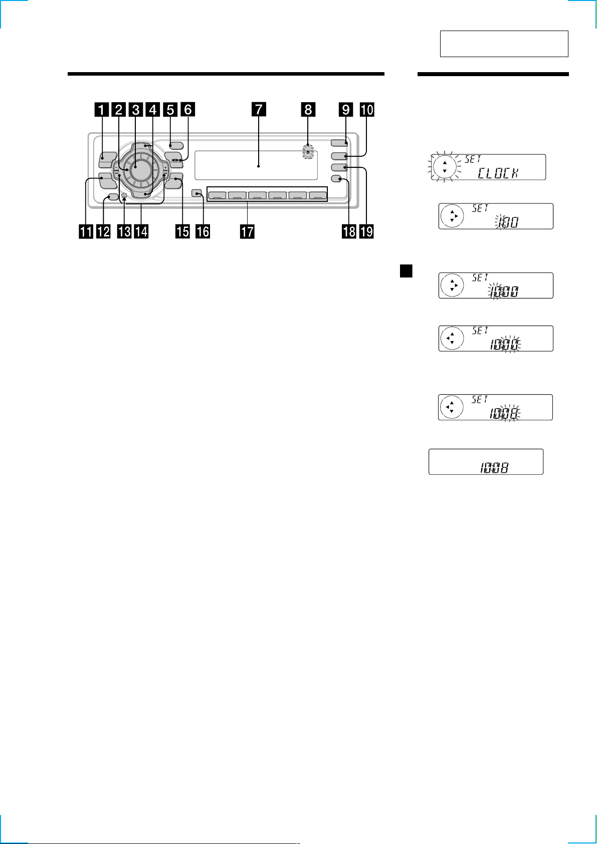
Location of controls
PTY
S
+
C
I
D
MENU
SOURCE
SOUND
P
R
S
T
-
-
D
I
S
OFF
Refer to the pages listed for details.
1 MENU button
9, 11, 12, 13, 15, 17, 19, 22, 24
2 Volume control dial
3 SOURCE (TUNER/TAPE/CD*1/MD*1)
button 8, 10, 12, 13, 16, 23
4 XR-C5300RV:
PRST/DISC +/– (cursor up/down) buttons
8, 9, 11, 12, 13, 15, 17, 18, 19, 22, 24
XR-4300RV:
PRST +/– (cursor up/down) buttons
8, 9, 11, 12, 13, 15, 17, 18, 19, 22, 24
During radio reception:
Preset stations select 13
During CD/MD playback*1:
Disc change 25
5 DSPL/PTY (display mode change/
programme type) button
11, 14, 18, 23, 24
6 MODE button 10, 11, 12, 13, 23
During tape playback:
Playback direction change 10
During radio reception:
BAND select 12
During CD/MD playback*1:
CD/MD unit select 23
7 Display window
8
Z (eject) button (located on the front side
of the unit behind the front panel) 10
9 OPEN button 7, 10, 26
q; D-BASS button 23
qa SOUND button 21
qs OFF button*2 7, 8, 10
DSPL
-
P
R
S
T
+
MODE
-
SEEK/AMS
ENTER
–
C
OPEN
D-BASS
AF
REP SHUF
1 2 3 4 56
XR-C5300RV
qd Reset button (located on the front side
of the unit behind the front panel) 7
qf SEEK/AMS –/+ (cursor left/right) buttons
8, 9, 10, 11, 12, 13, 15, 17, 19, 21, 22, 24, 25
Seek 13, 15
Automatic Music Sensor 10, 25
Manual search 13, 25
qg ENTER button
9, 11, 12, 13, 15, 17, 18, 19, 22, 24
qh Receptor for the card remote
commander
qj Number buttons
During radio reception:
Preset number select 12, 13, 16, 17
During tape playback:
(1) REP 11
During CD/MD playback*1:
(1) REP 25
(2) SHUF 25
qk AF button 15, 17
ql TA button 16, 17
*1XR-C5300RV only
*2Warning when installing in a car
without ACC (accessory) position on
the ignition key switch
Be sure to press (OFF) on the unit for
two seconds to turn off the clock display
after turning off the engine.
When you press (OFF) only momentarily,
the clock display does not turn off and this
causes battery wear.
Setting the clock
The clock uses a 24-hour digital indication.
Example: To set the clock to 10:08
1 Press (MENU), then press either side of
(PRST/DISC) or (PRST) repeatedly until
“CLOCK” appears.
TA
1 Press (ENTER).
The hour indication flashes.
2 Press either side of (PRST/DISC) or
(PRST) to set the hour.
3 Press (+) side of (SEEK/AMS).
The minute indication flashes.
4 Press either side of (PRST/DISC) or
(PRST)
to set the minute.
2 Press (ENTER).
The clock starts.
After the clock setting is complete, the
display returns to normal playback mode.
Tips
• You can use the convenient CT function to set
the clock automatically (page 19).
• When the D.INFO mode is set to ON, the time is
always displayed (page 22).
5
3
Installation
Instalación
Montering
Instalação
Precautions
•If you mount other Sony equipment with this
unit, it is better to mount this unit in the lower
position.
•There must be a distance of at least 15 cm
between the cassettes slot of the unit and shift
lever to insert cassette easily. Choose the
installation location carefully so the unit does
not interfere with gear shifting and other driving
operations.
•Choose the installation location carefully so that
the unit will not interfere with normal driving
operations.
•Avoid installing the unit in areas subject to dust,
dirt, excessive vibration, or high temperatures,
such as in direct sunlight or near heater ducts.
•Use only the supplied mounting hardware for a
safe and secure installation.
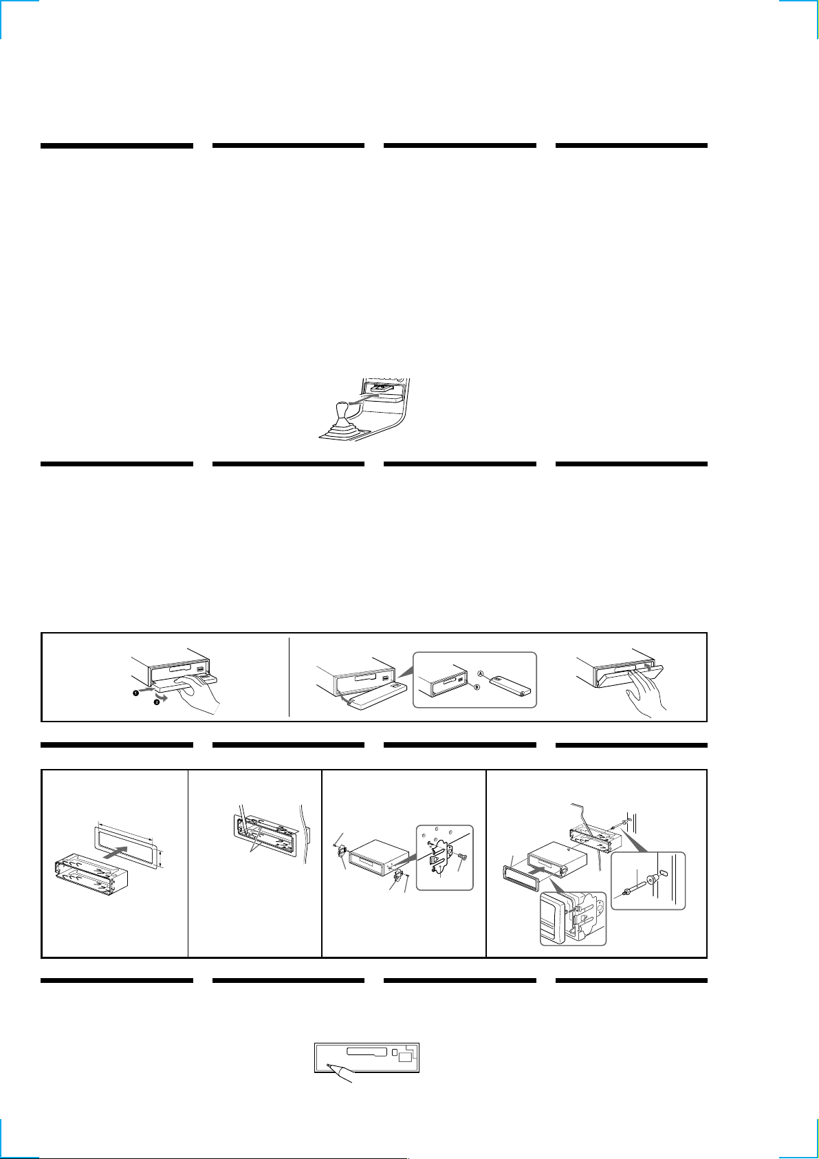
Mounting angle adjustment
Adjust the mounting angle to less than 20°.
How to detach and attach the
front panel
Before installing the unit, detach the front
panel.
A To detach
Before detaching the front panel, be sure to press
(OFF). Press (OPEN), then slide the front panel to
the right side, and pull out the left side.
B To attach
Place the hole A in the front panel onto the
spindle B on the unit as illustrated, then push the
left side in.
Precauciones
•Si monta otro equipo Sony con esta unidad, es
preferible montar esta unidad en la posición más
baja.
•Para que sea posible insertar la cinta con
facilidad, debe haber una distancia de al menos
15 cm entre la ranura de inserción de cintas de la
unidad y la palanca de cambios.
Instale la unidad en un lugar que no entorpezca
las operaciones de cambio de marchas o de
conducción en general.
•Elija cuidadosamente el lugar de montaje de
forma que la unidad no interfiera las funciones
normales de conducción.
•Evite instalar la unidad donde pueda quedar
sometida a altas temperaturas, como a la luz
solar directa o al aire de calefacción, o a polvo,
suciedad, o vibraciones excesivas.
•Para realizar una instalación segura y firme,
utilice solamente la ferretería de montaje
suministrada.
Ajuste del ángulo de montaje
Ajuste el ángulo de montaje a menos de 20°.
15 cm
Forma de extraer e instalar el
panel frontal
Antes de instalar la unidad, extraiga el panel
frontal.
A Para extraerlo
Antes de extraer el panel frontal, ceriórese de
pulsar (OFF). Después pulse (OPEN) a fin de
abrirlo, después deslícelo hacia la derecha, y por
último tire de su parte izquierda.
B Para instalarlo
Coloque el orificio A del panel frontal en el eje B
de la unidad, como se muestra en la ilustración, y
después presione la parte izquierda.
Säkerhetsföreskrifter
•Om du monterar annan Sony-utrustning till
denna enhet är det bäst att montera denna enhet
i det undre läget.
•För att du ska kunna sätta i och ta ut bandet
måste avståndet vara minst 15 cm mellan
kassettfacket på enheten och växelspaken. När
du installerar enheten väljer du en plats så att
enheten inte är i vägen när du kör.
•Var noga när du väljer var i bilen du monterar
bilstereon, så att den inte sitter i vägen när du
kör.
•Montera inte bilstereon där den utsätts för
värme,
t ex solsken eller varmluft, eller där den utsätts
för damm, smuts och/eller vibrationer.
•Använd endast de medföljande
monteringstillbehören för att vara säker på att
bilstereon monteras på ett säkert och korrekt
sätt.
Tillåten monteringsvinkel
Monteringsvinkeln får inte vara större än 20
grader.
Ta loss/fästa frontpanelen
Ta loss frontpanelen innan du monterar
bilstereon.
A Ta loss frontpanelen
Var noga med att trycka på (OFF) innan
frontpanelen tas loss. Tryck därefter på (OPEN)
för att öppna frontpanelen. Skjut frontpanelen åt
höger och dra dess vänstra del utåt för att ta loss
frontpanelen.
B Fästa frontpanelen
Placera frontpanelen så att hålet A på
frontpanelen träs över axeln B på bilstereon
enligt illustrationen. Tryck därefter frontpanelens
vänstra del inåt.
Precauções
•É preferível montar este aparelho na posição
mais baixa, se quiser montar simultaneamente
outros equipamentos da Sony.
•Para colocar com facilidade a cassete, deve haver
uma distância de pelo menos 15 cm entre a
ranhura de introduçäo da cassete e a alavanca
das mudanças.
Escolha o local de instalaçäo de forma a que o
aparelho näo interfira com as mudanças de
velocidade ou com as outras manobras de
conduçäo.
•Escolha com cuidado um local apropriado para
a montagem do aparelho, para que este não
interfira com as manobras necessárias à
condução do veículo.
•Evite instalar o aparelho onde possa estar sujeito
a altas temperaturas, como em locais expostos
directamente à luz do sol, ao ar quente dos
aquecimentos, ou sujeitos a pó, sujidade ou
vibração excessiva.
•Para efectuar uma instalação segura utilize
unicamente o hardware de montagem fornecido.
Ajuste do ângulo de montagem
Ajuste o ângulo de montagem a menos de 20°.
Para retirar e colocar o painel
frontal
Retire o painel frontal antes de iniciar a
instalação do aparelho.
A Para retirar
Antes de retirar o painel frontal, tem de carregar
primeiro em (OFF). A seguir, carregue em
(OPEN) para soltar o painel frontal e empurre-o
para a direita. Depois puxe o lado esquerdo do
painel para fora.
B Para colocar
Coloque o orificio A do painel frontal no eixo B
do aparelho tal como ilustrado, e depois carregue
no lado esquerdo para dentro.
A
Installation in the dashboard
1
182 m
m
53 mm
1
Reset button
When the installation and connections are
complete, be sure to press the reset button with a
ballpoint pen, etc.
B
Instalación en el salpicadero Montera på instrumentbrädan
2
Bend these claws outward
for a tight fit, if necessary.
Si es necesario, doble estas
uñas hacia fuera para que
encaje firmemente.
För att få en tät passning
böj dessa flikar vid behov.
Se necessário, dobre as
unhas para prender melhor.
Botón de restauración
Cuando finalice la instalación y las conexiones,
cerciórese de pulsar el botón de restauración con
un bolígrafo, etc.
3
5
6
6
5
Nollställningsknappen
Kom ihåg att använda en penna eller något annat
spetsigt föremål för att trycka på
nollställningsknappen när anslutningen och
monteringen är klar.
5
6
4
Dashboard
Salpicadero
Instrumentbräda
Tablier
4
c
Instalação no tablier
Fire wall
Panel cortafuegos
Brandsäker
mellanvägg
1
Botão de reinicialização
Quando terminar a instalação e as ligações, não se
esqueça de carregar no botão de reinicialização
com a ponta de uma caneta, esferográfica, etc.
Painel corta-fogo
2
3
4

Connections
Conexiones
Anslutning
Ligações
Cautions
•This unit is designed for negative earth 12 V DC
operation only.
•Be careful not to pinch any wires between a
screw and the body of the car or this unit or
between any moving parts such as the seat
railing, etc.
•Connect the power connecting cord 8 to the
unit and speakers before connecting it to the
auxiliary power connector.
•Run all earth wires to a common earth point.
•Connect the yellow cord to a free car circuit
rated higher than the unit’s fuse rating. If you
connect this unit in combination with other
stereo components, the car circuit they are
connected to must be rated higher than the sum
of the individual components’ fuse rating. If
there are no car circuits rated as high as the
unit’s fuse rating, connect the unit directly to the
battery. If no car circuits are available for
connecting this unit, connect the unit to a car
circuit rated higher than the unit’s fuse rating in
such a way that if the unit blows its fuse, no
other circuits will be cut off.
Warning when installing in a car
without ACC (accessory) position
on the ignition key switch
Be sure to press (OFF) on the unit for two
seconds to turn off the clock display after
turned off the engine.
When you press (OFF) momentarily, the clock
display does not turn off and this causes battery
wear.
Precauciones
•Esta unidad ha sido diseñada para alimentarse
con 12 V CC, negativo a masa, solamente.
•Tenga cuidado de no atrapar ningún cable entre
algún tornillo y la carrocería del automóvil o
esta unidad o entre las partes móviles, como por
ejemplo los raíles del asiento, etc.
•Conecte el cable de conexión de alimentación 8
a la unidad y los altavoces antes de conectarlo al
conector de alimentación auxiliar.
•Conecte todos los conductores de puesta a
masa a un punto común.
•Conecte el cable amarillo a un circuito libre del
automóvil de potencia nominal superior a la del
fusible de la unidad. Si conecta esta unidad en
combinación con otros componentes estéreo, la
potencia nominal del circuito del automóvil a los
que dichos componentes estén conectados debe
ser superior a la suma de la potencia nominal
del fusible de los componentes. Si no existen
circuitos de automóvil de potencia nominal tan
alta como la del fusible de la unidad, conecte
ésta directamente a la batería. Si no hay circuitos
de automóvil disponibles para conectar esta
unidad, conecte la misma a un circuito de
automóvil de potencia nominal superior a la del
fusible de la unidad de forma que no se
desactiven otros circuitos si el fusible de dicha
unidad se funde.
Advertencia sobre la instalación
en un automóvil que no
disponga de posición ACC
(accesorios) en el interruptor de
la llave de encendido
Asegúrese de pulsar (OFF) en la unidad
durante dos segundos para desactivar la
indicación del reloj una vez apagado el motor.
Si pulsa (OFF) momentáneamente, la indicación
del reloj no se desactivará y esto causará el
desgaste de la batería.
Säkerhetsföreskrifter
•Denna bilstereo är endast avsedd för anslutning
till ett negativt jordat, 12 V bilbatteri.
•Var noga med att inga kablar kläms mellan
någon skruv eller att de blir klämda mellan
rörliga delar som t.ex. bilsätet.
•Anslut strömkabeln 8 till enheten och
högtalarna innan du ansluter den till den yttre
strömanslutningen.
•Dra samtliga jordledningar till en och samma
jordningspunkt.
•Anslut den gula kabeln till en ledig bilkrets med
ett högre amperetal än enhetens. Om du kopplar
både denna enhet och andra stereokomponenter
till en och samma bilkrets, måste den bilkrets de
kopplas till ha en högre ampere än summan av
de enskilda delarnas amperestyrka. Om det inte
finns några bilkretsar med en så hög
amperestyrka som enhetens ska du ansluta
enheten direkt till batteriet. Om inga bilkretsar
finns för anslutning till enheten ska du ansluta
enheten till en bilkrets med ett högre amperetal
än enhetens säkring, så att det är denna som går
i stället för bilens.
Var försiktig n är du gör
installationen i en bil där
tändningslåset saknar
tillbeh örsläge (ACC)
Glöm inte att trycka på (OFF) på enheten
under två sekunder för att stänga av klockans
teckenfönster efter det att du har stängt av
motorn.
Om du bara trycker på (OFF) ett kort ögonblick
slocknar inte klockans teckenfönster vilket kan
leda till att batteriet laddas ur.
Cuidado
•Este aparelho foi concebido para funcionar
somente com corrente contínua de 12 V com
negativo à massa.
•Tenha cuidado para que os fios não fiquem
entalados entre os parafusos e a carroçaria do
automóvel ou a caixa do aparelho nem entre as
peças móveis, por exemplo, as calhas dos
bancos, etc.
•Ligue o cabo de alimentação de corrente 8 ao
aparelho e aos alifalantes antes de o ligar ao
conector de corrente auxiliar.
•Ligue todos os cabos de massa num ponto de
massa comum.
•Ligue o cabo amarelo a um circuito eléctrico
livre do automóvel, cuja potência nominal seja
superior à dos fusíveis do aparelho. Se ligar este
aparelho em série com outros componentes
estéreo, a potência nominal do circuito eléctrico
do automóvel onde os ligar tem de ser superior
à soma da potência nominal dos fusíveis de
todos os componentes individuais. Se não
houver nenhum circuito eléctrico do automóvel
com uma potência nominal tão elevada como a
dos fusíveis do aparelho, ligue-o directamente à
bateria. Se não estiver disponível nenhum
circuito eléctrico do automóvel para ligação
deste aparelho, ligue-o a um circuito eléctrico do
automóvel com uma potência nominal superior
à dos fusíveis do aparelho, de tal modo que, se o
aparelho rebentar os fusíveis respectivos,
nenhum outro circuito seja cortado.
Aviso sobre a instalação num
automóvel sem posição ACC
(acessórios) na chave de ignição
Verifique se carregou em (OFF) no aparelho
durante dois segundos para desactivar o visor
do relógio depois de ter desligado o motor.
Se carregar ligeiramente em (OFF), não desactiva
o visor do relógio o que provoca o desgaste da
bateria.
Notes of connection example
Notes on the control leads
• The power aerial control lead (blue) supplies +12 V
DC when you tur n on the tuner or when you
activate the ATA (Automatic Tuner Activation), AF
(Alternative Frequency) or the TA (Traffic
Announcement) function.
• A power aerial without a relay box cannot be used
with this unit.
• When your car has a built-in FM/MW/LW aerial in
the rear/side glass, it is necessary to connect the
power aerial control lead (blue) or the accessory
power input lead (red) to the power terminal of the
existing aerial booster. For details, consult your
dealer.
Warning
If you have a power aerial without a relay box,
connecting this unit with the supplied power
connecting cord 8 may damage the aerial.
Memory hold connection
When the yellow power input lead is connected,
power will always be supplied to the memory circuit
even when the ignition switch is turned off.
Notes on speaker connection
• Before connecting the speakers, turn the unit off.
• Use speakers with an impedance of 4 to 8 ohms, and
with adequate power handling capacities.
Otherwise, the speakers may be damaged.
• Do not connect the terminals of the speaker system
to the car chassis, and do not connect the terminals
of the right speaker with those of the left speaker.
• Do not attempt to connect the speakers in parallel.
• Do not connect any active speakers (with built-in
amplifiers) to the speaker terminals of the unit.
Doing so may damage the active speakers. Be sure
to connect passive speakers to these terminals.
Notas de ejemplo de conexiones
Notas sobre cables de control
• El cable de control (azul) de la antena motorizada
suministra + 12 V CC al activar el sintonizador o la
funci ón ATA (activaci ó n autom ática del
sintonizador), AF (frecuencias alternativas) o TA
(anuncios de tráfico).
• Con esta unidad no podr á utilizarse una antena
motorizada sin caja de relés.
• Si el autom óvil dispone de antena de FM/MW/LW
incorporada en el cristal trasero/lateral, será
necesario conectar el cable de control de antena
motorizada (azul) o el cable de entrada de
alimentaci ón accesoria (rojo) al terminal de potencia
del amplificador de antena existente. Para más
informaci ón, consulte con el proveedor.
Advertencia
Si dispone de una antena motorizada sin dispositivo
de rel é, la conexión de esta unidad con el cable de
conexió n de alimentaci ón 8 suministrado puede
dañar la antena.
Conexión para protección de la memoria
Si conecta el cable de entrada de alimentaci ón
amarillo, el circuito de la memoria recibirá siempre
alimentaci ó n, incluso aunque ponga la llave de
encendido en la posición de apagado.
Notas sobre la conexión de los altavoces
• Antes de conectar los altavoces, desconecte la
alimentaci ón de la unidad.
• Utilice altavoces con una impedancia de 4 a
8 ohmios, y con la potencia máxima admisible
adecuada, ya que de lo contrario podr ía dañarlos.
• No conecte los terminales del sistema de altavoces al
chasis del autom óvil, ni los del altavoz izquierdo a
los del derecho.
• No intente conectar los altavoces en paralelo.
• No conecte altavoces activos (con amplificadores
incorporados) a los terminales de altavoces de la
unidad. Si lo hiciese, podría dañ ar tales altavoces.
Por lo tanto, cerciórese de conectar altavoces pasivos
a estos terminales.
Att observera angående
anslutningsexemplen
Att observera angående de olika styrkablarna
• Motorantennens styrkabel (bl å) leder + 12 volts
likstr öm när kanalv äljaren slås på eller när
radiomottagningsautomatik ATA, mottagning av
alternativa frekvenser AF eller mottagning av
trafikmeddelanden TA aktiverats.
• En motorantenn utan styrrel ädosa kan inte anslutas
till denna bilstereo.
• Om bilen har en FM/MW/LW-antenn som är inbyggd
i sido- eller bakrutan, m åste du ansluta
motorantennens styrkabel (bl å) eller
tilbeh ö rsströmkabeln (röd) till strömterminalen på
antennf örstärkaren. Din återf örsäljare kan ge dig
mer information.
Varning
Om du har en motorantenn utan relädosa kan
antennen skadas om du ansluter enheten med den
medf öljande str ömkabeln 8.
Anslutning för minnesstöd
När du anslutit den gula, ing ående strömkabeln
fö rsörjs minneskretsen med ström hela tiden, även när
tändl åset slås ifr ån.
Att observera angående högtalarnas anslutning
• Slå av bilstereon innan du ansluter hö gtalarna.
• Anslut endast högtalare, vars impedans varierar fr ån
4 till 8 ohm och som har tillr äcklig
effekthanteringskapacitet för att skydda högtalar na
mot skador.
• Anslut inte något av högtalar uttagen till bilens
chassi. Anslut inte heller uttagen p å h öger h ögtalare
till uttagen p å vänster högtalare.
• Anslut inte högtalar na parallellt.
• Anslut inte aktiva högtalare (med inbyggda slutsteg)
till bilstereons högtalaruttag, eftersom de kan skada
de aktiva högtalarna. Var noga med att bara ansluta
passiva högtalare till dessa uttag.
Notas sobre o exemplo de
ligação
Notas sobre os fios de controlo
• O fio de controlo da antena eléctr ica (azul) fornece
+12 V CC quando ligar o sintonizador ou quando
activar as fun ções ATA (Activa ção autom ática do
sintonizador), AF (frequ ência alternativa) ou TA
(Informa ções de tr ânsito).
• Não pode utilizar uma antena el éctrica sem caixa de
relé com este aparelho.
• Se o seu autom ó vel tiver uma antena de FM/MW/LW
montada no vidro traseiro/lateral, tem de ligar o fio
de controlo da antena eléctrica (azul) ou o fio de
entrada de alimenta ção para os acessórios
(vermelho) ao terminal de alimenta ção do
intensificador do sinal da antena existente.
Advertência
Se a antena eléctrica n ão tiver uma caixa de rel é, o
facto de ligar este aparelho com o cabo de
alimenta ção 8 fornecido, pode provocar danos na
antena.
Ligação para alimentação contínua da memória
Quando o fio amarelo de entrada de alimenta ção for
ligado, os circuitos de mem ória ficarão com
alimenta ção continua, mesmo se a chave de igni ção
estiver desligada.
Notas sobre a ligação dos altifalantes
• Antes de ligar os altifalantes, desligue o aparelho.
• Utilize altifalantes com imped ância de 4 a 8 ohm, e
com capacidade admissível de pot ência adequada.
Caso contrário, os altifalantes poder ão sofrer
avarias.
• Não ligue os terminais do sistema de altifalantes ao
chassis do autom óvel, e não ligue os terminais do
altifalante direito aos ter minais do altifalante
esquerdo.
• Não tente ligar os altifalantes em paralelo.
• Não ligue nenhum sistema de altifalantes activos
(com amplificadores incorporados) aos terminais dos
altifalantes do aparelho. Caso o faça, poder á avariar
o sistema de altifalantes activos. Portanto, não se
esqueça de ligar altifalantes passivos a estes
terminais.
5
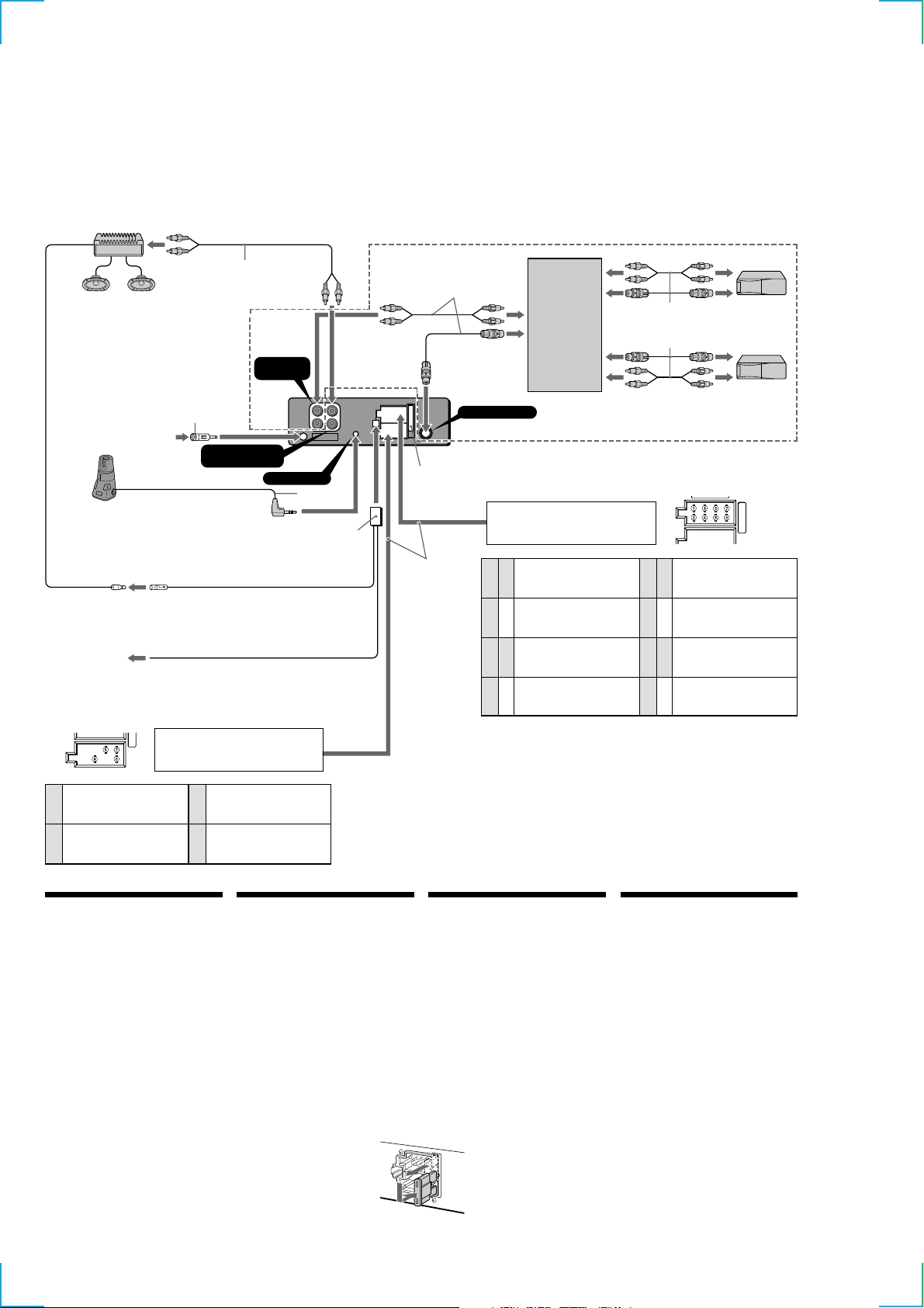
Connection example
Ejemplo de conexiones
Anslutningarna enligt exemplet
Exemplo de ligações
1
*
Note for the aerial connecting
If your car aerial is an ISO
(International Organization for
Standardization) type, use the
supplied adapter 7 to connect it.
First connect the car aerial to the
supplied adapter, then connect it to
the aerial jack of the master unit.
2
*
Insert with the cord upwards.
1
*
Nota sobre la conexión de la antena
Si la antena del automóvil es del
tipo ISO (International Organization
for Standardization), emplee el
adaptador suministrado 7 para
conectarla.
En primer lugar, conecte la antena
del automóvil al adaptador
suministrado y, a continuación, a la
toma de antena de la unidad
principal.
2
*
Insertar con el cable hacia arriba.
1
*
Angående antennanslutning
Om bilantennen är av ISO-typ
(International Organization for
Standardization), använder du
medföljande adapter 7 för att
ansluta den.
Anslut först bilantennen till
medföljande adapter och därefter
till antennuttaget på
huvudenheten.
2
*
Sätt in med kabeln vänd uppåt.
1
*
Nota referente à ligação da antena
Se a antena do automóvel for uma
antena de tipo ISO (International
Organization for Standardization),
utilize o adaptador fornecido 7
para fazer a ligação respectiva.
Ligue primeiro a antena do
automóvel ao adaptador fornecido
e depois à tomada de antena do
sistema principal.
2
*
Inserir com o fio virado para cima.
from car aerial
de la antena del automóvil
från bilantenn
da antena do automóvel
to the interface cable of
a car telephone
al cable de interfaz de
un teléfono para
automóvil
till mobiltelefonens
gränssnittskabel
Ao cabo de interface de
um telefone para
automóvel
RCA pin cord (not supplied)
Cable con clavijas RCA (no suministrado)
Kabel med RCA-kontakter (medföljer inte)
Cabo de terminais RCA (não fornecido)
1
*
1
*
Rotary commander RM-X4S (not supplied)
Mando rotativo RM-X4S (no suministrado)
Vridkontroll RM-X4S (medföljer inte)
Comando rotativo RM-X4S (não fornecido)
7
1
*
1
*
AMP REM
Max. supply current 0.3 A
Corriente máx. de alimentación de 0,3 A
Maximal strömtillförsel 0,3 A
Corrente máxima de 0,3 A
ATT
from the car’s power connector
del conector de alimentación del automóvil
från bilens strömanslutning
a partir do conector de alimentação do automóvel
AUDIO OUT
(LINE OUT) REAR
BUS AUDIO
IN
REMOTE IN
Blue/white striped
Con raya azul/blanca
Blå/vit-randig
Azul com listras brancas
Supplied to XA-C30
Suministrado con el XA-C30
Medföljer XA-C30
Fornecido para o XA-C30
Source selector
Selector de fuente
Väljare för ljudkälla
Selector de fonte
BUS CONTROL IN
Fuse (10 A)
Fusible (10 A)
2
*
9
Light blue
Azul celeste
HimmelsBlå
Azul claro
Säkring (10 A)
Fusivel (10 A)
8
from the car’s speaker connector
del conector de altavoz del automóvil
från bilens högtalaranslutning
a partir do conector do altifalante do automóvel
Speaker, Rear, Right
Altavoz, Parte posterior, Derecho
+
1
2
3
4
Negative polarity positions 2, 4, 6, and 8 have striped cords.
Las posiciones de polaridad negativa 2, 4, 6 y 8 tienen cables con raya.
De negativa polpositionerna 2, 4, 6 och 8 har randiga kablar.
As posições 2, 4, 6 e 8 (polaridade negativa) têm cabos às riscas.
Högtalare, Bakre, Höger
Altifalante, Parte de trás, Direito
Speaker, Rear, Right
Altavoz, Parte posterior, Derecho
–
Högtalare, Bakre, Höger
Altifalante, Parte de trás, Direito
Speaker, Front, Right
Altavoz, Parte frontal, Derecho
+
Högtalare, Främre, Höger
Altifalante, Parte da frente, Direito
Speaker, Front, Right
Altavoz, Parte frontal, Derecho
–
Högtalare, Främre, Höger
Altifalante, Parte da frente, Direito
Supplied to the CD/MD changer
Suministrado con el cambiador de CD/MD
Medföljer CD/MD-växlaren
Fornecido para o permutador de CD/MD
XR-C5300RV only
XR-C5300RV solamente
endast C5300RV
somente C5300RV
Speaker, Front, Left
Altavoz, Parte frontal, Izquierdo
5
+
Högtalare, Främre, Vänster
Altifalante, Parte da frente, Esquerdo
Speaker, Front, Left
Altavoz, Parte frontal, Izquierdo
6
–
Högtalare, Främre, Vänster
Altifalante, Parte da frente, Esquerdo
Speaker, Rear, Left
Altavoz, Parte posterior, Izquierdo
7
+
Högtalare, Bakre, Vänster
Altifalante, Parte de trás, Esquerdo
Speaker, Rear, Left
Altavoz, Parte posterior, Izquierdo
8
–
Högtalare, Bakre, Vänster
Altifalante, Parte de trás, Esquerdo
continuous power supply
suministro de alimentación continua
4
kontinuerlig strömförsörjning
alimentação de corrente contínua
power aerial control
control de antena motorizada
5
motorantenn
antena eléctrica
suministro conmutado de alimentación
7
8
Power connection
Power connectors may vary depending on the car.
Check your car’s power connector diagram to make
sure the connections match correctly. There are two
basic types. You may need to switch the positions of
the jump connector. Before connecting the unit to the
car’s power supply, be sure to match the position of the
jump connector to the car’s pin order . If the power
connector of your car does not match the connector on
the unit, use the supplied connector 8. If you have any
questions or problems connecting your unit that are not
covered in this manual, please consult the car dealer.
WARNING
Jump connector
Check the pin position of the power connector of the
car with the table on the below. If positions 4 and 7 are
reversed, remove the jump connector and shift it to the
rightmost position as shown in the illustration.
switched power supply
switchad strömförsörjning
alimentação de corrente comutada
earth
toma de tierra
jord
Terra
Positions 1, 2, 3 and 6 do not have pins.
Las posiciones 1, 2, 3 y 6 no disponen de terminales.
Positionerna 1, 2, 3 och 6 saknar stift.
As posições 1, 2, 3 e 6 não têm pinos.
Conexión de alimentación
Los conectores de alimentación pueden variar en
función del automóvil. Consulte el diagrama del
conector de alimentación del automóvil para
comprobar que las conexiones coinciden
correctamente. Existen dos tipos básicos. Es posible que
sea necesario cambiar las posiciones del conector de
empalme. Antes de conectar la unidad al suministro de
alimentación del automóvil, asegúrese de que la
posición del conector de empalme coincide con el
orden de terminales de dicho automóvil. Si el conector
de alimentación del automóvil no coincide con el de la
unidad, emplee el conector 8 suministrado. Si desea
realizar alguna consulta o solucionar algún problema
referentes a la conexión de la unidad que no aparezcan
en este manual, póngase en contacto con el
concesionario automovilístico.
ADVERTENCIA
Conector de empalme
Compruebe la posición de terminal del conector de
alimentación del automóvil con la tabla que aparece
más abajo. Si las posiciones 4 y 7 se invierten, retire el
conector de empalme y desplácelo hasta la posición del
extremo derecho como se muestra en la ilustración.
Strömanslutningsschema
Strömanslutningarna kan variera beroende på vilken
bil du har. Kontrollera bilens diagram över
strömanslutningar för att kontrollera att
anslutningarna passar ihop. Det finns två huvudtyper.
Du kan behöva ändra positionerna på överkopplingen.
Innan du ansluter enheten till bilens strömförsörjning
bör du kontrollera att överkopplingens placering
överensstämmer med bilens polordning. Om din bils
strömanslutningar inte överenstämmer med
anslutningen på enheten använder du det medföljande
kontaktdonet 8. Om du har några frågor eller problem
när det gäller anslutningen av enheten som inte tas
upp i denna bruksanvisning kan du kontakta
bilåterförsäljaren.
VARNING
Överkoppling
Jämför bilens strömanslutning med tabellen till nedan.
Om positionerna 4 och 7 är omkastade tar du bort
överkopplingen och flyttar den till positionen längst till
höger.
Diagrama de ligação de corrente
Os conectores de alimentação podem variar de
automóvel para automóvel. Verifique o diagrama do
conector de alimentação do seu automóvel, para ter a
certeza de que a correspondência das ligações está
correcta. Há dois tipos básicos. Pode ter que trocar as
posições do cone etor de patilha. Antes de ligar o
aparelho à fonte de alimentação do automóvel, não se
esqueça de fazer a correspondência entre a posição do
cone etor de patilha e a ordem dos pinos do automóvel.
Se o conector de alimentação do seu automóvel não
corresponder ao conector do aparelho, utilize os
conector 8 fornecido. Se tiver dúvidas ou problemas
ao ligar o aparelho que não estejam referidos neste
manual, consulte o vendedor do automóvel.
AVISO
Conector jump
Verifique a posição dos pinos do conector de
alimentação do automóvel na tabela abaixo. Se as
posições 4 e 7 estiverem invertidas, remova o conector
jump e mude-o para a posição mais à direita, tal como
se mostra na ilustração.
6
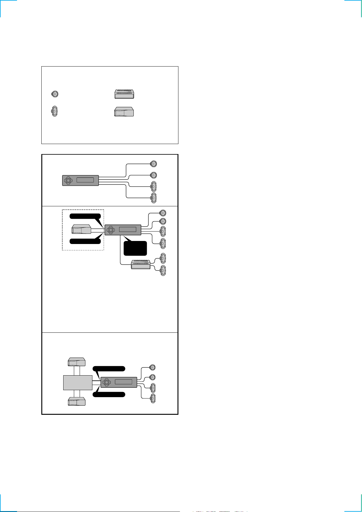
Connection diagram
Diagrama de conexiones
Kopplingsschema
Diagrama de ligações
Equipment used in illustrations (not supplied)
Equipo utilizado en las ilustraciones (no suministrado)
Utrustning som visas i illustrationer (medföljer inte)
Equipamento utilizado nas ilustrações (não fornecido)
Front speaker
Altavoz delantero
Främre högtalare
Altifalante dianteiro
Rear speaker
Altavoz trasero
Bakre högtalare
Altifalante traseiro
For connecting two or more changers, the source selector XA-C30 (optional) is necessary.
Si desea conectar dos o más cambiadores, necesitará el selector de fuente XA-C30 (opcional).
För anslutning av två eller flera växlare krävs väljaren XA-C30 (tillval).
Para ligar um ou mais permutadores, é necessário o selector de fonte XA-C30 (opcional).
Power amplifier
Amplificador de potencia
Effektförstärkare
Amplificador de potência
CD/MD changer
Cambiador de CD/MD
CD/MD-skivväxlare
Permutador CD/MD
A
B
*
Notes
• Be sure to connect the earth cord before connecting the amplifier.
• If you connect an optional power amplifier and do not use the built-in amplifier, the beep sound will be
Notas
• Asegúrese de conectar primero el cable de puesta a masa antes de realizar la conexión al amplificador.
• Si conecta un amplificador de potencia opcional y no utiliza el incorporado, los pitidos se desactivarán.
Obsevera
• Var noga med att först ansluta jorden, innan du ansluter förstärkaren.
• Om du väljer att använda en annan förstärkare i stället för den inbyggda, kommer ljudsignalen att
Notas
• Antes de fazer a ligação ao amplificador tem de ligar primeiro o cabo de ligação à massa.
• Se ligar um amplificador de potência opcional e não utilizar o amplificador integrado, desactiva o sinal
C
*
BUS AUDIO IN
BUS CONTROL IN
XR-C5300RV only
XR-C5300RV solamente
endast XR-C5300RV
somente XR-C5300RV
deactivated.
avaktiveras.
sonoro.
XR-C5300RV only
XR-C5300RV solamente
endast XR-C5300RV
somente XR-C5300RV
Source selector
Selector de fuente
Väljare för ljudkälla
Selector de fonte
BUS AUDIO IN
BUS CONTROL IN
AUDIO OUT
(LINE OUT)
REAR
7
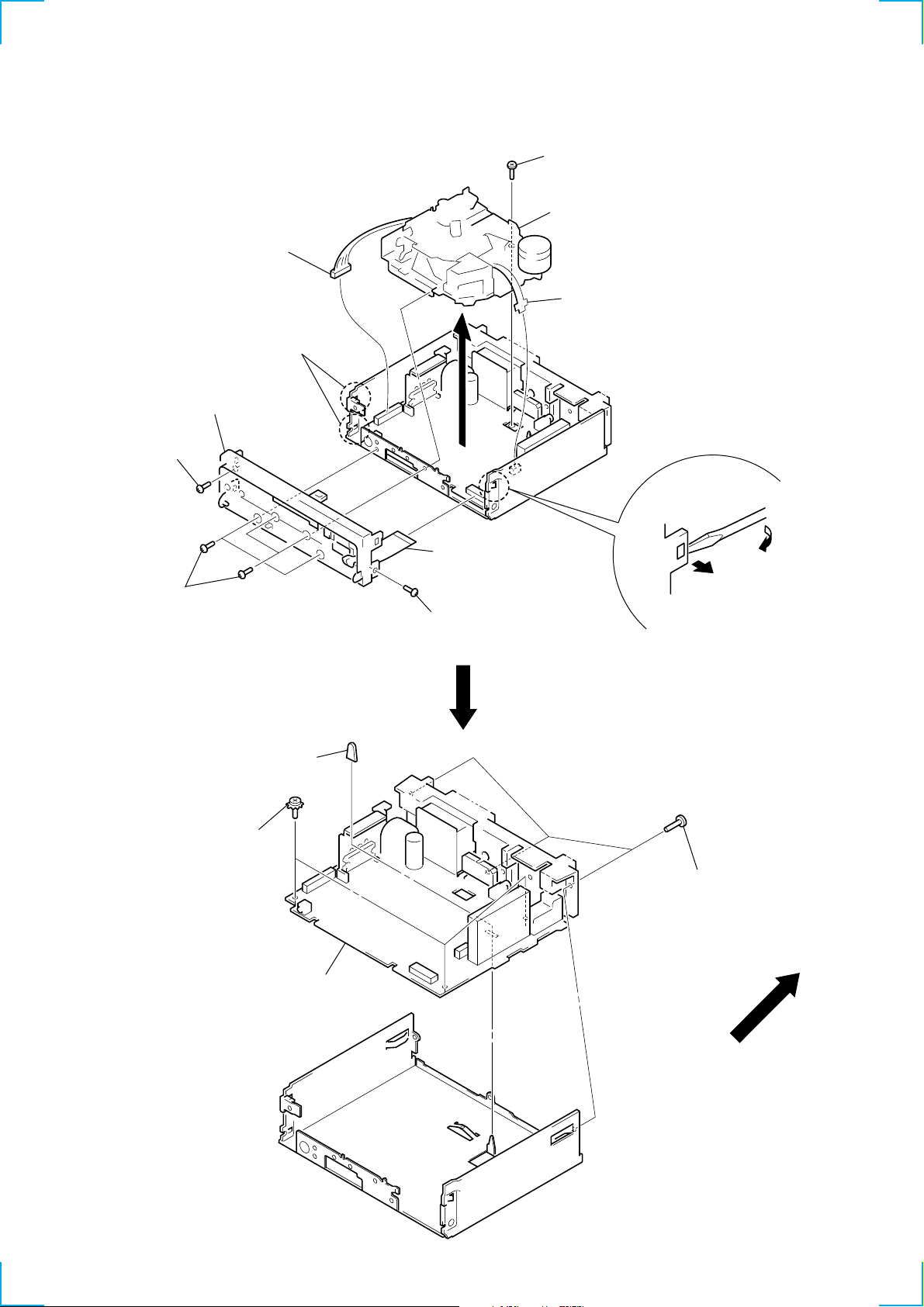
SECTION 2
DISASSEMBLY
Note: Follow the disassembly procedure in the numerical order given.
MECHANISM DECK (MG-25G-136)
6 connector
(CN302)
2 two claws
4 sub panel ass’y
1 screw (PTT2.6 × 6)
1 four screws
(PTT2.6 × 6)
3 connector
(CN701)
1 screw (PTT2.6 × 6)
7 screw (PTT2.6 × 6)
8 mechanism deck
(MG-25G-136)
5 flexible board
(CN301)
2 claw
MAIN BOARD
3 rubber cap (25)
2 three ground point
screws
1 three screws
(PTT2.6 × 8)
4 main board
8
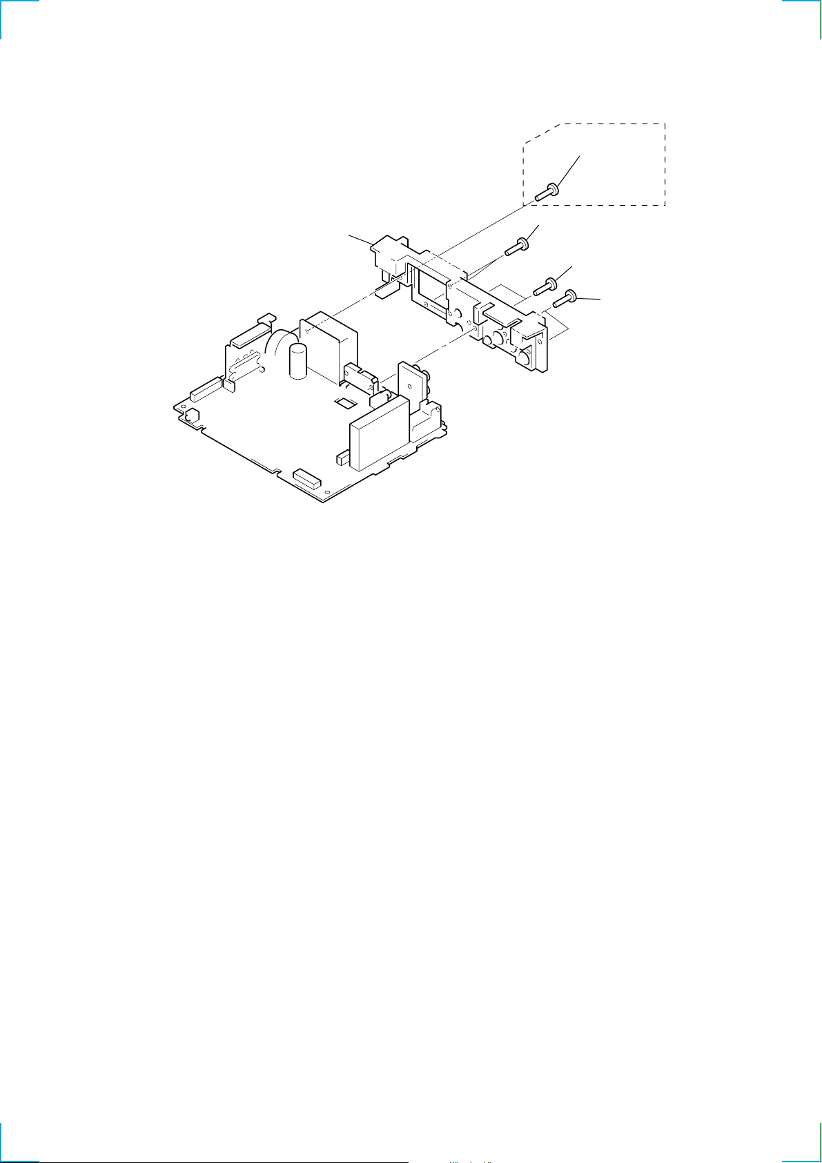
HEAT SINK
)
2 heat sink
1 screw (PTT2.6 × 10)
XR-C5300RV
1 two screws
(PTT2.6 × 10)
1 two screws
(PTT2.6 × 10)
1 two screws
(PTT2.6 × 10
9
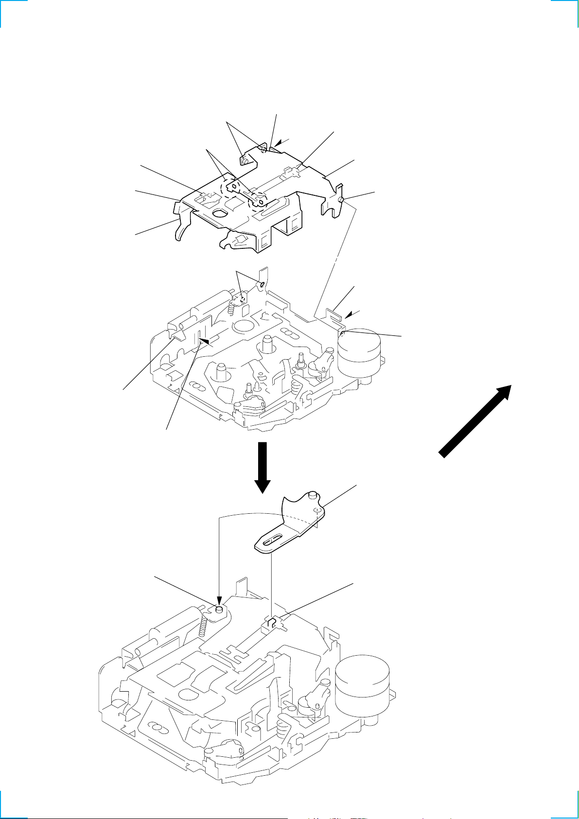
SECTION 3
ASSEMBLY OF MECHANISM DECK
Note: Follow the assembly procedure in the numerical order given.
HOUSING
5 Fit projection on C part.
2 Install the hanger onto
two claws of the housing.
4 Fit claw on B part.
7 Hold the hanger by bending the claw.
1 Install the catch to the hanger.
hanger
3 Put the housing
under A part.
housing
A part
6 Fit projection on D part.
C part
8 Hold the hanger by
bending the claw.
D part
B part
ARM (SUCTION)
2 Move the arm (suction) in the arrow
direction and fit on projection.
projection
1 Fit the arm (suction) on the shaft.
10
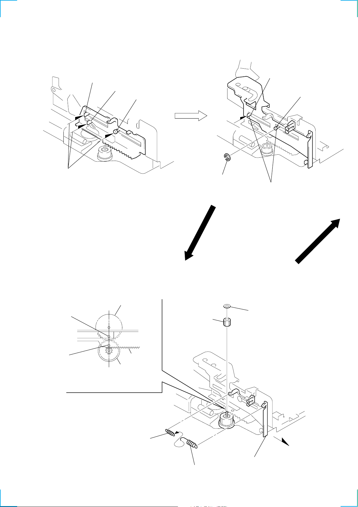
LEVER (LDG-A) / (LDG-B)
shaft A
1 Fit the lever (LDG-A) on
shafts A – C and install it.
shaft B
shaft C
shaft A
shaft B
3 type-E stop ring 2.0
2 Fit the lever (LDG-B) on
shafts A and B and
install it.
GEAR (LDG-FT)
hole
hole
gear (LDG-D)
6 polyethylene washer
5 gear (LDG-FT)
lever (LDG-A)
gear (LDG-FB)
4 Align hole in the gear (LDG-D)
with hole the lever (LDG-A).
1
2 tension spring (LD-2)
2 tension spring (LD-1)
3 Move the lever (LDG-B)
in the direction of the arrow .
11
GUIDE (C)
2 guide (C)
1 three claws
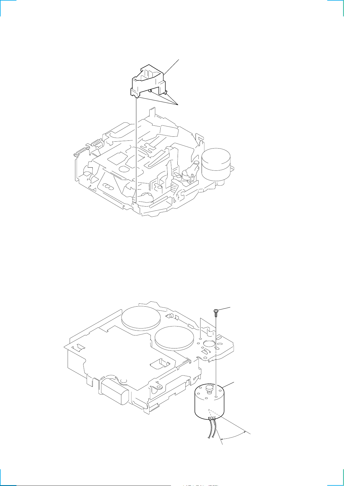
MOUNTING POSITION OF CAPSTAN/REEL MOTOR (M901)
two precision screws
(P2 × 2)
capstan/reel motor
(M901)
12
30˚

SECTION 4
r
MECHANICAL ADJUSTMENT
SECTION 5
ELECTRICAL ADJUSTMENT
1. Clean the follo wing parts with a denatured-alcohol-moistened
swab:
playback head pinch roller
rubber belt capstan
idler
2. Demagnetize the playback head with a head demagnetizer.
3. Do not use a magnetized screwdriver for the adjustments.
4. After the adjustments, apply suitable locking compound to the
parts adjusted.
5. The adjustments should be performed with the power supply
voltage unless otherwise noted.
• T orque Measurement
Mode Torque Meter Meter Reading
Forward CQ-102C (30 – 65 g•cm)
Forward
Back Tension
Reverse CQ-102RC (30 – 65 g•cm)
Reverse
Back Tension
FF, REW CQ-201B (60 – 200 g•cm)
CQ-102C (0.5 – 4.5g•cm)
CQ-102RC (0.5 – 4.5g•cm)
2.95 – 6.37 mN•m
(0.42 – 0.90 oz•inch)
0.05 – 0.44 mN•m
(0.01 – 0.06 oz•inch)
2.95 – 6.37 mN•m
(0.42 – 0.90 oz•inch)
0.05 – 0.44 mN•m
(0.01 – 0.06 oz•inch)
5.89 – 19.61 mN•m
(0.83 – 2.78 oz•inch)
• T ape Tension Measurement
Mode Tension Meter Meter Reading
Forward CQ-403A (more than 90 g)
Reverse CQ-403R (more than 90 g)
more than 8.83 mN•m
(more than 3.18 oz)
more than 8.83 mN•m
(more than 3.18 oz)
TAPE DECK SECTION
0 dB=0.775 V
Tape Speed Adjustment
Setting:
speed checker
or
test tape
WS-48A
(3 kHz, 0 dB)
set
AUDIO OUT jack (CNJ151)
frequency counte
10 kΩ
+–
Procedure:
1. Put the set into the FWD PB mode.
2. Adjust adjustment resistor for inside capstan motor so that the
reading on the speed checker or frequency counter becomes in
specification.
Specification: Constant speed
Speed checker Frequency counter
–1.5 to +2.5% 2,955 to 3,075 Hz
Adjustment Location:
– SET UPPER VIEW –
Tape Speed Adjustment
TUNER SECTION
Tuner section adjustments are done automatically in this set.
1313
 Loading...