

Sony XR-4954X Service Manual
XR-4950X/4954X
SERVICE MANUAL
Photo: XR-4950X
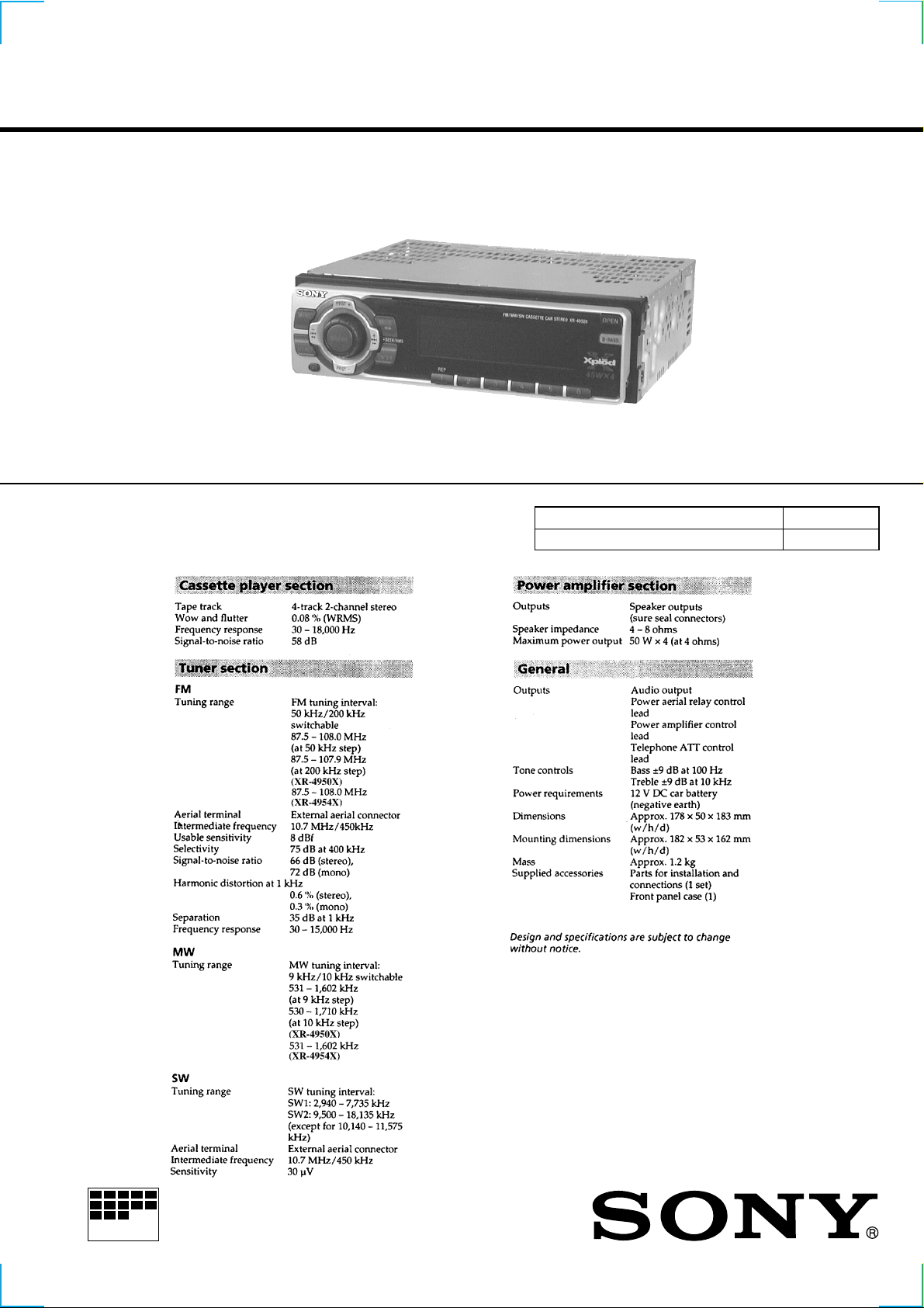
SPECIFICATIONS
E Model
Model Name Using Similar Mechanism XR-C5100
T ape Transport Mechanism Type MG-25F-136
MICROFILM
FM/MW/SW CASSETTE CAR STEREO
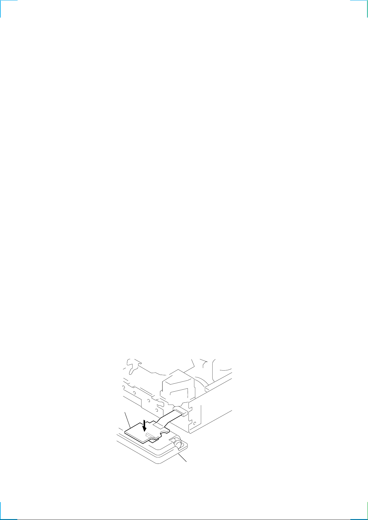
TABLE OF CONTENTS
1. SERVICE NOTE ............................................................. 2
2. GENERAL ........................................................................ 3
3. DISASSEMBLY .............................................................. 13
Flexible Circuit Board Repairing
• Keep the temperature of the soldering iron around 270 ˚C during repairing.
• Do not touch the soldering iron on the same conductor of the
circuit board (within 3 times).
• Be careful not to apply force on the conductor when soldering
or unsoldering.
4. ASSEMBLY OF MECHANISM DECK................ 14
5. MECHANICAL ADJUSTMENTS ............................ 17
6. ELECTRICAL ADJUSTMENTS
6-1. Test Mode........................................................................ 17
• Tape Deck Section ........................................................ 17
• Tuner Section................................................................ 17
7. DIAGRAMS
7-1. Block Diagrams
• TUNER/TAPE/MAIN Section ..................................... 18
• DISPLAY/KEY CONTROL/BUS CONTROL/
POWER SUPPLY Section ........................................... 19
7-2. Printed Wiring Board – MAIN Board – ......................... 21
7-3. Schematic Diagram – MAIN Board (1/2) – ................... 22
7-4. Schematic Diagram – MAIN Board (2/2) – ................... 23
7-5. Printed Wiring Boards – KEY/SUB Boards – .............. 24
7-6. Schematic Diagrams – KEY/SUB Boards – .................. 25
7-7. IC Block Diagrams ......................................................... 26
7-8. IC Pin Function ............................................................... 27
8. EXPLODED VIEWS................................................ 32
9. ELECTRICAL PARTS LIST ............................... 35
Notes on chip component replacement
• Never reuse a disconnected chip component.
• Notice that the minus side of a tantalum capacitor may be damaged by heat.
SERVICE NOTE
Please press on the sub board from above when checking it.
This assures that the connector does not lose contact.
SUB board
SECTION 1
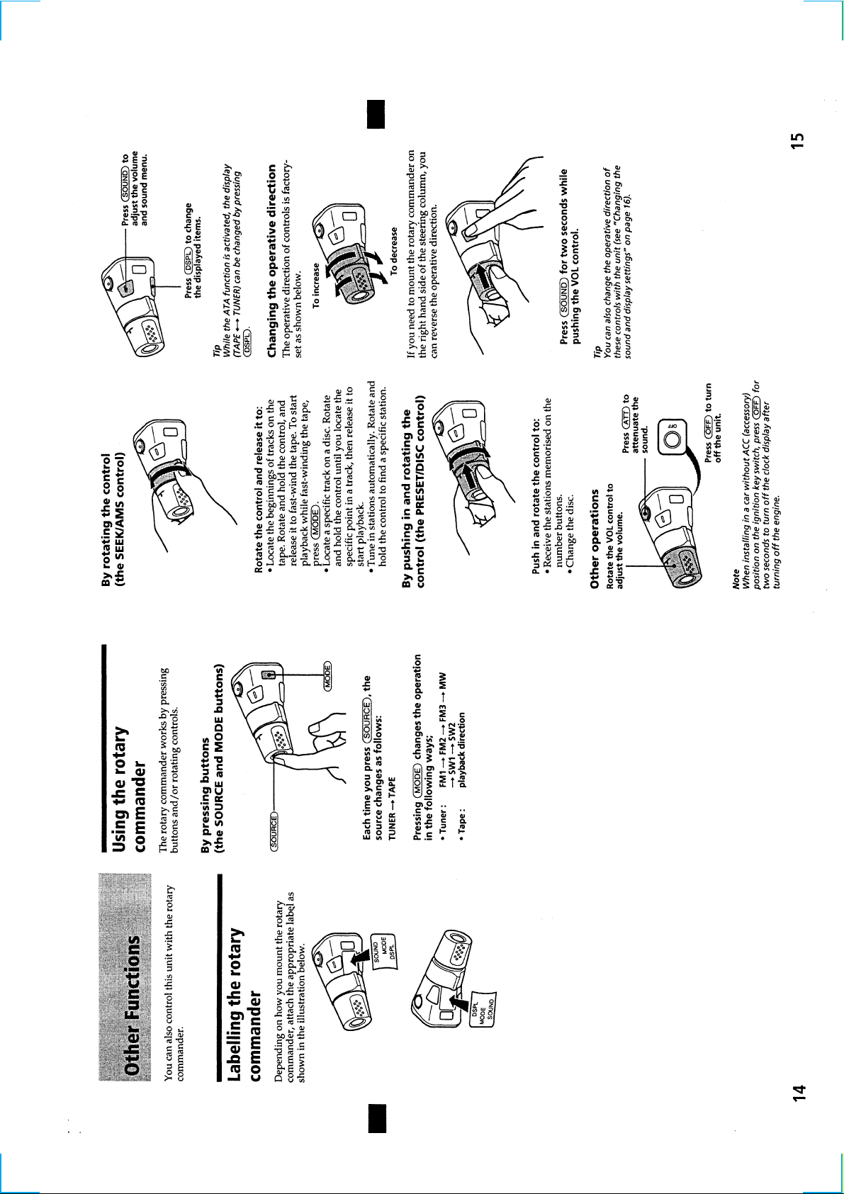
Front panel assembly
2
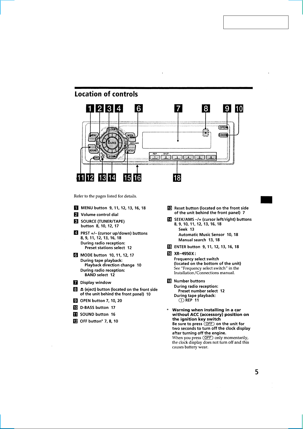
SECTION 2
GENERAL
This section is extracted from
instruction manual.
3
456789101112
 Loading...