

Sony XR-4803 User Manual
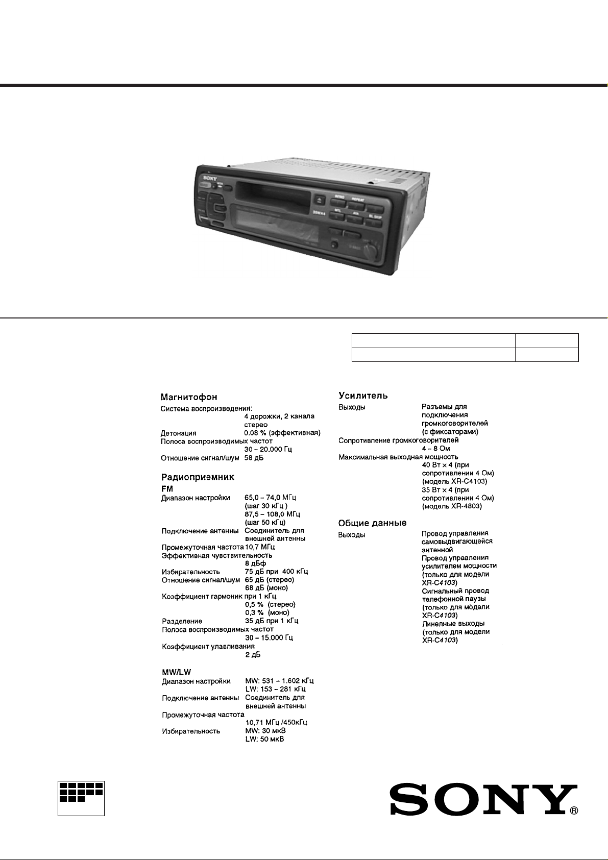
XR-4803
SERVICE MANUAL
SPECIFICA TIONS
East European Model
Model Name Using Similar Mechanism NEW
Tape T ransport Mechanism T ype MG-25F-136
MICROFILM
– Continued on next page –
FM/MW/LW CASSET TE CAR STEREO
TABLE OF CONTENTS
1. GENERAL ................................................................... 3
2. DISASSEMBLY ......................................................... 9
3. ASSEMBLY OF MECHANISM DECK........... 11
4. MECHANICAL ADJUSTMENTS ....................... 14
5. ELECTRICAL ADJUSTMENTS
Test Mode........................................................................ 14
Tape Deck Section .......................................................... 14
Tuner Section .................................................................. 15
6. DIAGRAMS
6-1. IC Pin Function Description ........................................... 17
6-2. Printed Wiring Board – MAIN Section –...................... 21
6-3. Schematic Diagram – MAIN Section –.......................... 23
6-4. Printed Wiring Board – PANEL Section – .................... 27
6-5. Schematic Diagram – PANEL Section –....................... 29
7. EXPLODED VIEWS ................................................ 33
8. ELECTRICAL PARTS LIST ............................... 36
Flexible Circuit Board Repairing
• Keep the temperature of the soldering iron around 270 ˚C during repairing.
• Do not touch the soldering iron on the same conductor of the
circuit board (within 3 times).
• Be careful not to apply force on the conductor when soldering
or unsoldering.
Notes on chip component replacement
• Never reuse a disconnected chip component.
• Notice that the minus side of a tantalum capacitor may be damaged by heat.
– 2 –
SECTION 1
GENERAL
This section is extracted from
instruction manual.
– 3 –
– 4 –
– 5 –
– 6 –
– 7 –
– 8 –
SECTION 2
1
3
cover ass’y
2
2
2
1
1
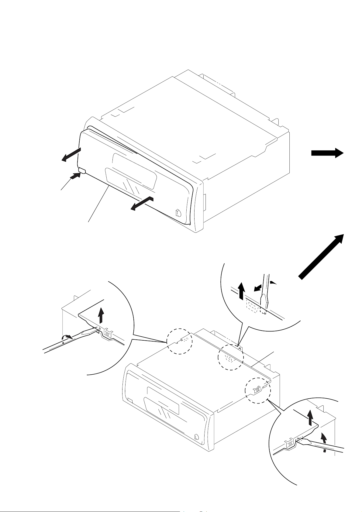
DISASSEMBLY
Note: Follow the disassembly procedure in the numerical order given.
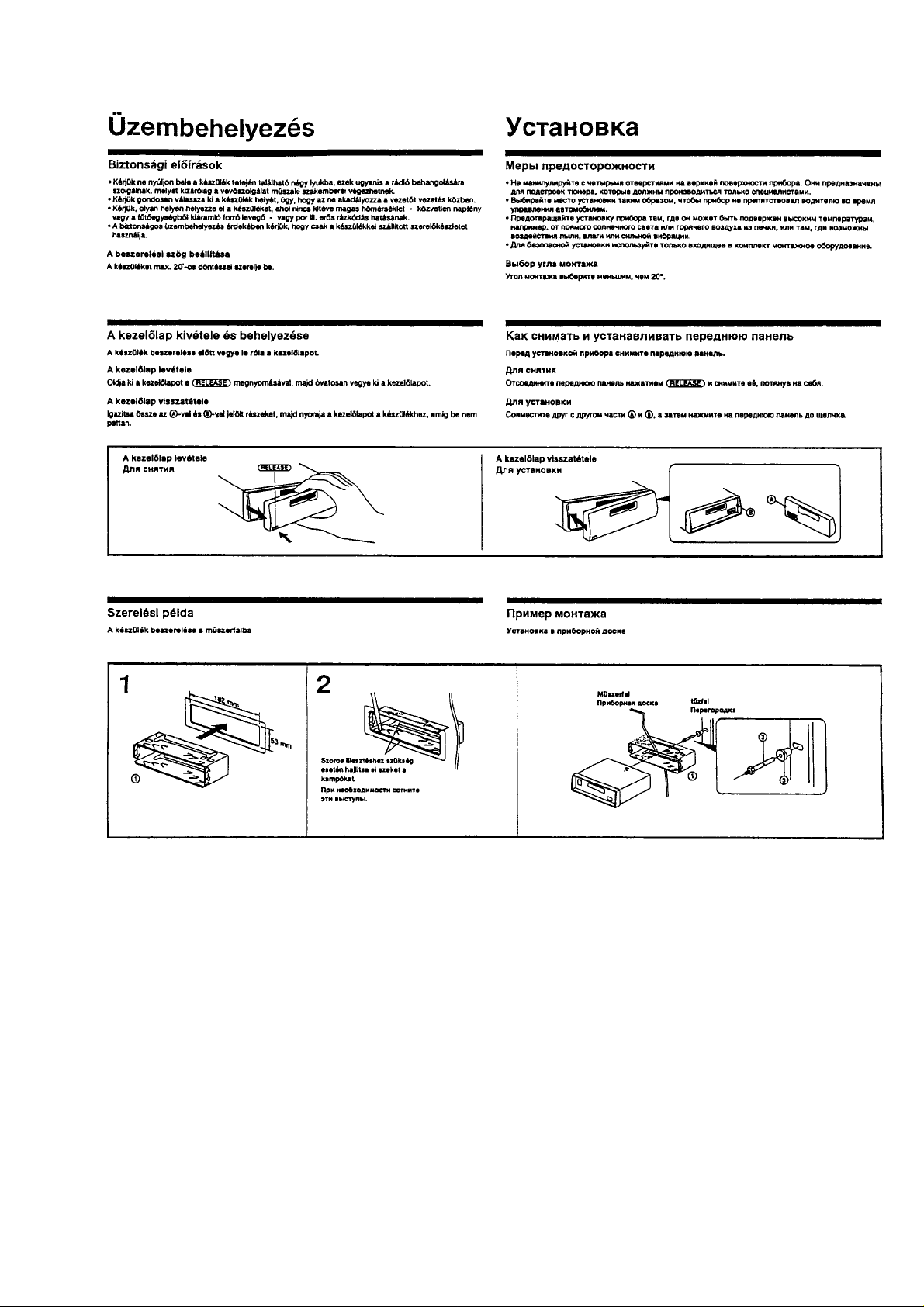
FRONT PANEL ASS’Y
Push the button
1
(release).
2
Remove the front panel ass’y
to the direction of the arrow A.
COVER ASS’Y
A
– 9 –
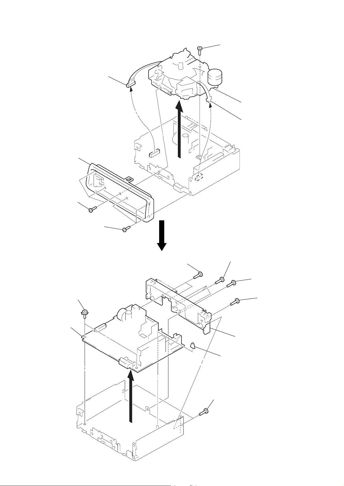
SUB PANEL, MECHANISM DECK (MG-25F-136)
k
3
connector
(CN351)
2
sub panel
1
three screws
(PTT2.6
×
8)
5
screw
(PTT2.6
×
6)
6
mechanism dec
(MG-25F-136)
4
flexible flat cable
(CN301)
1
three screws
(PTT2.6
MAIN BOARD, HEAT SINK
3
two ground point
screws
4
main board
×
8)
5
two screws
(PTT2.6
×
5)
5
three screws
(PTT2.6
6
heat sink
2
rubber cap (25)
1
×
10)
5
screw
(PTT2.6
screw
(PTT2.6
×
8)
×
8)
– 10 –
1
two screws
(PTT2.6
×
8)
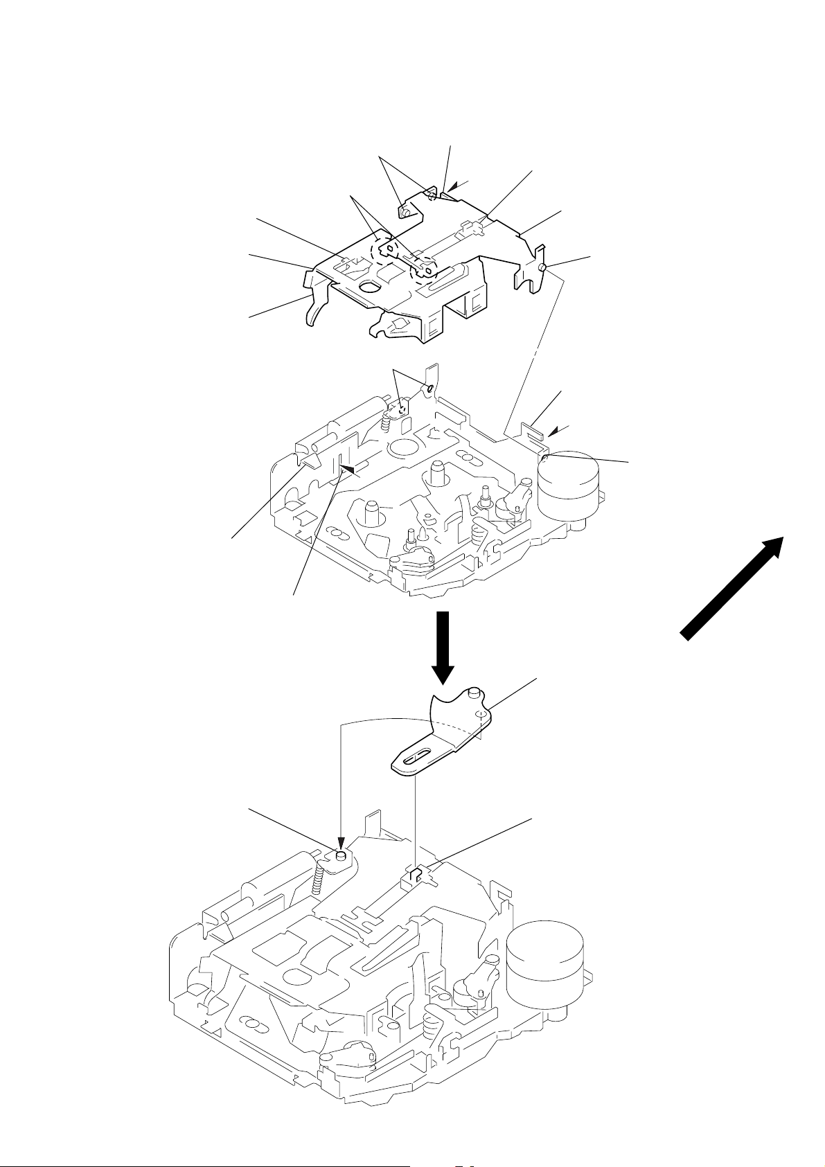
SECTION 3
ASSEMBLY OF MECHANISM DECK
Note: Follow the assembly procedure in the numerical order given.
HOUSING
4
Fit claw on B part.
3
Put the housing
under A part.
housing
2
Install the hanger onto
two claws of the housing.
5
Fit projection on C part.
C
part
7
Holder the hanger by bending the claw.
1
Install the catch to the hanger.
hanger
6
Fit projection on D part.
8
Hold the hanger by
bending the claw.
ARM (SUCTION)
A
part
projection
B
part
D
part
2
Move the arm (suction) in the arrow
direction and fit on projection.
1
Fit the arm (suction) on the shaft.
– 11 –
 Loading...